EP1625865A1 - Einweg Spritze mit einziehbarer Nadel - Google Patents
Einweg Spritze mit einziehbarer Nadel Download PDFInfo
- Publication number
- EP1625865A1 EP1625865A1 EP04254805A EP04254805A EP1625865A1 EP 1625865 A1 EP1625865 A1 EP 1625865A1 EP 04254805 A EP04254805 A EP 04254805A EP 04254805 A EP04254805 A EP 04254805A EP 1625865 A1 EP1625865 A1 EP 1625865A1
- Authority
- EP
- European Patent Office
- Prior art keywords
- disposed
- disposable syringe
- surrounding
- anchored
- segment
- Prior art date
- Legal status (The legal status is an assumption and is not a legal conclusion. Google has not performed a legal analysis and makes no representation as to the accuracy of the status listed.)
- Granted
Links
Images


Classifications
-
- A—HUMAN NECESSITIES
- A61—MEDICAL OR VETERINARY SCIENCE; HYGIENE
- A61M—DEVICES FOR INTRODUCING MEDIA INTO, OR ONTO, THE BODY; DEVICES FOR TRANSDUCING BODY MEDIA OR FOR TAKING MEDIA FROM THE BODY; DEVICES FOR PRODUCING OR ENDING SLEEP OR STUPOR
- A61M5/00—Devices for bringing media into the body in a subcutaneous, intra-vascular or intramuscular way; Accessories therefor, e.g. filling or cleaning devices, arm-rests
- A61M5/178—Syringes
- A61M5/31—Details
- A61M5/32—Needles; Details of needles pertaining to their connection with syringe or hub; Accessories for bringing the needle into, or holding the needle on, the body; Devices for protection of needles
- A61M5/3205—Apparatus for removing or disposing of used needles or syringes, e.g. containers; Means for protection against accidental injuries from used needles
- A61M5/321—Means for protection against accidental injuries by used needles
- A61M5/322—Retractable needles, i.e. disconnected from and withdrawn into the syringe barrel by the piston
- A61M5/3234—Fully automatic needle retraction, i.e. in which triggering of the needle does not require a deliberate action by the user
-
- A—HUMAN NECESSITIES
- A61—MEDICAL OR VETERINARY SCIENCE; HYGIENE
- A61M—DEVICES FOR INTRODUCING MEDIA INTO, OR ONTO, THE BODY; DEVICES FOR TRANSDUCING BODY MEDIA OR FOR TAKING MEDIA FROM THE BODY; DEVICES FOR PRODUCING OR ENDING SLEEP OR STUPOR
- A61M5/00—Devices for bringing media into the body in a subcutaneous, intra-vascular or intramuscular way; Accessories therefor, e.g. filling or cleaning devices, arm-rests
- A61M5/178—Syringes
- A61M5/31—Details
- A61M5/32—Needles; Details of needles pertaining to their connection with syringe or hub; Accessories for bringing the needle into, or holding the needle on, the body; Devices for protection of needles
- A61M5/3205—Apparatus for removing or disposing of used needles or syringes, e.g. containers; Means for protection against accidental injuries from used needles
- A61M5/321—Means for protection against accidental injuries by used needles
- A61M5/322—Retractable needles, i.e. disconnected from and withdrawn into the syringe barrel by the piston
- A61M5/3221—Constructional features thereof, e.g. to improve manipulation or functioning
- A61M2005/323—Connection between plunger distal end and needle hub proximal end, e.g. stud protruding from the plunger
-
- A—HUMAN NECESSITIES
- A61—MEDICAL OR VETERINARY SCIENCE; HYGIENE
- A61M—DEVICES FOR INTRODUCING MEDIA INTO, OR ONTO, THE BODY; DEVICES FOR TRANSDUCING BODY MEDIA OR FOR TAKING MEDIA FROM THE BODY; DEVICES FOR PRODUCING OR ENDING SLEEP OR STUPOR
- A61M5/00—Devices for bringing media into the body in a subcutaneous, intra-vascular or intramuscular way; Accessories therefor, e.g. filling or cleaning devices, arm-rests
- A61M5/178—Syringes
- A61M5/31—Details
- A61M5/32—Needles; Details of needles pertaining to their connection with syringe or hub; Accessories for bringing the needle into, or holding the needle on, the body; Devices for protection of needles
- A61M5/3205—Apparatus for removing or disposing of used needles or syringes, e.g. containers; Means for protection against accidental injuries from used needles
- A61M5/321—Means for protection against accidental injuries by used needles
- A61M5/322—Retractable needles, i.e. disconnected from and withdrawn into the syringe barrel by the piston
- A61M5/3221—Constructional features thereof, e.g. to improve manipulation or functioning
- A61M2005/3231—Proximal end of needle captured or embedded inside piston head, e.g. by friction or hooks
-
- A—HUMAN NECESSITIES
- A61—MEDICAL OR VETERINARY SCIENCE; HYGIENE
- A61M—DEVICES FOR INTRODUCING MEDIA INTO, OR ONTO, THE BODY; DEVICES FOR TRANSDUCING BODY MEDIA OR FOR TAKING MEDIA FROM THE BODY; DEVICES FOR PRODUCING OR ENDING SLEEP OR STUPOR
- A61M5/00—Devices for bringing media into the body in a subcutaneous, intra-vascular or intramuscular way; Accessories therefor, e.g. filling or cleaning devices, arm-rests
- A61M5/178—Syringes
- A61M5/31—Details
- A61M5/32—Needles; Details of needles pertaining to their connection with syringe or hub; Accessories for bringing the needle into, or holding the needle on, the body; Devices for protection of needles
- A61M5/3205—Apparatus for removing or disposing of used needles or syringes, e.g. containers; Means for protection against accidental injuries from used needles
- A61M5/321—Means for protection against accidental injuries by used needles
- A61M5/322—Retractable needles, i.e. disconnected from and withdrawn into the syringe barrel by the piston
- A61M5/3234—Fully automatic needle retraction, i.e. in which triggering of the needle does not require a deliberate action by the user
- A61M2005/3241—Needle retraction energy is accumulated inside of a hollow plunger rod
-
- A—HUMAN NECESSITIES
- A61—MEDICAL OR VETERINARY SCIENCE; HYGIENE
- A61M—DEVICES FOR INTRODUCING MEDIA INTO, OR ONTO, THE BODY; DEVICES FOR TRANSDUCING BODY MEDIA OR FOR TAKING MEDIA FROM THE BODY; DEVICES FOR PRODUCING OR ENDING SLEEP OR STUPOR
- A61M5/00—Devices for bringing media into the body in a subcutaneous, intra-vascular or intramuscular way; Accessories therefor, e.g. filling or cleaning devices, arm-rests
- A61M5/50—Devices for bringing media into the body in a subcutaneous, intra-vascular or intramuscular way; Accessories therefor, e.g. filling or cleaning devices, arm-rests having means for preventing re-use, or for indicating if defective, used, tampered with or unsterile
- A61M5/508—Means for preventing re-use by disrupting the piston seal, e.g. by puncturing
Definitions
- This invention relates to a disposable syringe, more particularly to a disposable syringe with a friction diminishing means for facilitating retraction of a needle into a tubular plunger.
- the object of the present invention is to provide a disposable syringe which permits steady retraction of a plunger and which ensures successful retraction of a needle assembly.
- the disposable syringe includes a needle cannula, a tubular needle seat, a barrel, a tubular grip member, a tubular plunger, a coupling member and a biasing member.
- the tubular needle seat includes a front hub portion which is disposed to fix the needle cannula therein, a gripped portion which extends from the front hub portion in a longitudinal direction, and a rear anchoring portion which is disposed opposite to the front hub portion in the longitudinal direction.
- the barrel has an inner surrounding barrel surface which surrounds an axis in the longitudinal direction and which defines a passage therein.
- the passage has rearward and forward openings opposite to each other in the longitudinal direction.
- the inner surrounding barrel surface includes a larger-diameter portion and a smaller-diameter portion which are disposed proximate to the rearward and forward openings, respectively.
- the larger-diameter portion has a retaining area which is spaced apart from the smaller-diameter portion in the longitudinal direction.
- the smaller-diameter portion includes a retaining region which is disposed proximate to the larger-diameter portion and which is configured to retain the front hub portion thereat when the needle seat is in a position of use, and a friction diminishing region which extends from the retaining region toward the forward opening and which terminates at a shoulder abutment.
- the shoulder abutment defines a communicating hole which permits passage of the needle cannula therethrough, and is spaced apart from the front hub portion along the axis in the position of use.
- the tubular grip member in the position of use, is disposed to bring the gripped portion into engagement with the retaining area by virtue of a first frictional force generated therebetween.
- the tubular plunger is disposed to be movable in the passage along the larger-diameter portion.
- the plunger has a front opened end wall which is movable to abut against the grip member, a rear opened end wall which is disposed opposite to the front opened end wall and which extends outwardly of the rearward opening so as to be manually operable, and an intermediate surrounding wall which is interposed between the front and rear opened end walls and which defines an accommodation chamber.
- the coupling member has a surrounding retained portion which surrounds the axis and which is disposed in the accommodation chamber to be in frictional engagement with the intermediate surrounding wall by virtue of a second frictional force, and an anchored portion which is disposed adjacent to the front opened end wall in the position of use, which confronts the rear anchoring portion, and which is engageable with the rear anchoring portion by a holding force when the coupling member is moved forwardly towards the forward opening.
- a pushing force subsequently applied to the plunger causes the anchored portion to rub against the rear anchoring portion, which remains unmoved in place due to engagement of the front hub portion with the shoulder abutment, so that the anchored portion is engaged with the rear anchoring portion and is moved relative to the intermediate surrounding wall towards the rear opened end wall so as to release the surrounding retained portion from the intermediate surrounding wall, thereby enabling the anchored portion to be moved from the position of use to a retracted position where the anchored portion is disposed closer to the rear opened end wall, and where the needle seat and the needle cannula are received in the accommodation chamber.
- the biasing member is disposed to bias the anchored portion towards the retracted position.
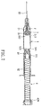
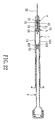
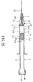
- the first preferred embodiment of a disposable syringe according to the present invention is shown to comprise a needle assembly 2, a barrel 1, a tubular grip member 3, a tubular plunger 4, a coupling member 51, and a biasing member 52.
- the needle assembly 2 includes a needle cannula 22 and a tubular needle seat 21.
- the needle seat 21 is in the form of a hard thin wall tube, such as a metal or carbon fiber tube which includes a front segment 211 to serve as a front hub portion 211 that is disposed to fix the needle cannula 22 therein, and a rear segment that extends from the front segment along an axis (X) in a longitudinal direction.
- the rear segment has outer and inner segment surfaces opposite to each other in radial directions relative to the axis (X) to serve as a gripped portion 212 and a rear anchoring portion 213, respectively.
- the barrel 1 has an inner surrounding barrel surface 13 which surrounds the axis (X) in the longitudinal direction and which defines a passage 10 therein.
- the passage 10 has rearward and forward openings 132,131 which are disposed opposite to each other in the longitudinal direction.
- the inner surrounding barrel surface 13 includes a larger-diameter portion 11 and a smaller-diameter portion 12 which are disposed proximate to the rearward and forward openings 132, 131, respectively, anannular shoulder 14 which converges gradually from the larger-diameter portion 11 to the smaller-diameter portion 12, and a plurality of ribs 15 which are formed on an inner surface of the shoulder 14 to retain a part of the front hub portion 211 of the needle seat 21.
- the larger-diameter portion 11 has a retaining area 16 which is in the form of an annular protrusion and which is spaced apart from the smaller-diameter portion 12 in the longitudinal direction.
- the smaller-diameter portion 12 includes a retaining region 121 which is disposed in connection with the ribs 15 and which is configured to retain a part of the front hub portion 211 of the needle seat 21 thereat when the needle seat 21 is in a position of use, and a friction diminishing region 122 which extends from the retaining region 121 toward the forward opening 131 and which terminates at a shoulder abutment 124.
- the passage 10 at the friction diminishing region 122 has a diameter larger than that of the passage 10 at the retaining region 121.
- the shoulder abutment 124 defines a communicating hole 123 which is configured to permit passage of the needle cannula 22 therethrough, and is spaced apart from the front hub portion 211 along the axis (X) in the position of use.
- the tubular grip member 3 In the position of use, the tubular grip member 3 is disposed, to bring the gripped portion 212 of the needle seat 21 into engagement with the retaining area 16 by virtue of a first frictional force generated therebetween.
- the grip member 3 is in fluid-tight and frictional engagement with the retaining area 16, and has an axially extending hole 31 for receiving the gripped portion 212.
- the tubular plunger 4 is disposed to be movable in the passage 10 along the larger-diameter portion 11.
- the plunger 4 has a front opened end wall 421 which is movable to abut against the grip member 3, a rear opened end wall 422 which is disposed opposite to the front opened end wall 421 and which extends outwardly of the rearward opening 132 so as to be manually operable, and an intermediate surrounding wall 42 which is interposed between the front and rear opened end walls 421,422 and which defines an accommodation chamber 41.
- the intermediate surrounding wall 42 has a smaller front segment 423 and a larger rear segment 424 disposed proximate to the front and rear opened end walls 421, 422 , respectively, to form a shoulder 426 therebetween.
- An enlarged terminal segment 425 is disposed between the larger rear segment 424 and the rear opened end wall 422, and is formed with a vent hole 429 so as to be in fluid communication with the ambient atmosphere.
- An annular rib 428 is disposed between the larger rear segment 424 and the enlarged terminal segment 425, and extends in the longitudinal direction.
- An end cap 44 is disposed to cover the rear opened end wall 422, and has an annular groove 441 for engagement with the enlarged terminal segment 425.
- an annular groove 427 is formed in an inner peripheral surface of the larger rear segment 424 proximate to the shoulder 426.
- a seal ring 43 which is made of a deformable material, is sleeved retainingly over an outer peripheral surface of the smaller front segment 423 so as to be slidable on and to be in fluid-tight frictional engagement with both the larger-diameter portion 11 of the inner surrounding barrel surface 13 and the coupling member 51.
- the coupling member 51 has a surrounding retained portion 512 which surrounds the axis (X) and which is in the form of an annular protrusion disposed to be in frictional engagement with the annular groove 427 in the intermediate surrounding wall 42 by virtue of a second frictional force, an anchored portion 514 which extends forwardly of the front opened end wall 421 in the position of use to confront the rear anchoring portion 213 so as to be engageable with the rear anchoring portion 213 by a holding force when the coupling member 51 is moved forwardly towards the forward opening 131, a retained shank portion 513 which is disposed between the surrounding retainedportion 512 and the anchored portion 514 and which extends in the accommodation chamber 41 at the smaller front segment 423 so as to stabilize the coupling member 51 at the smaller front segment 423, and a shank portion 511 which extends from the surrounding retained portion 512 distal from the anchored portion 514.
- the biasing member 52 is a coiled spring, and has a front spring end 521 which engages the shank portion 511, and a rear spring end 522 which is retained between the annular rib 428 and the intermediate surrounding wall 42 such that the coiled spring 52 is tensioned when the surrounding retained portion 512 is in frictional engagement with the annular groove 427 by virtue of the second frictional force, as shown in Fig. 2.
- the plunger 4 is pressed forwardly by a pushing force to permit abutment of the seal ring 43 against the grip member 3.
- the anchored portion 514 is extended into the axially extending hole 31.
- a manual pushing force is further applied to the plunger 4 to push the grip member 3 forward against the first frictional force (i.e., the frictional engagement between the grip member 3 and the retaining area 16) such that the anchored portion 514 is partially extended into and engaged with the rear anchoring portion 213, and such that the front hub portion 211 moves past the friction diminishing region 122 to abut against the shoulder abutment 124.
- the front hub portion 211 can be pushed forwards relative to the smaller-diameter portion 12 so that the friction between the front hub portion 211 and the smaller-diameter portion 12 to be overcome in the course of retraction of the needle assembly 2 into the accommodation chamber 41 by the coiled spring 52 can be reduced.
- the substantially continuing forward movement of the needle seat 21 relative to the smaller-diameter portion 12 after the injection course and its subsequently rearward movement due to retraction of the needle assembly 2 by the coiled spring 52 transform the static friction between the front hub portion 211 and the smaller-diameter portion 12 into a kinetic friction, which can be easily overcome by the predetermined biasing force of the coiled spring 52 in the course of retraction of the needle assembly 2 into the accommodation chamber 41, thereby ensuring successful and smooth retraction of the needle assembly 2.
- the needle seat 21 is in the form of a metal tube, it can be configured to have a relatively small diameter.
- the needle cannula 22 can be formed to have a relatively small diameter, as shown in Figs. 1 to 5, so as to be adapted for injecting medication of a very small volume, such as 1 ml.
- the barrel 1 can be configured to have a smaller diameter with a relatively compensatory elongation of the length of the barrel for a unit medication volume.
- the spacing of graduations (not shown) marked on the barrel 1 of extremely small volume, such as 1 cc., and smaller ones can be relatively large to facilitate accurate reading of the volume of medication in injection course.
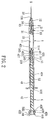
- the second preferred embodiment of a disposable syringe according to this invention is similar to the first preferred embodiment in construction, but is adapted for injecting medication of a general volume, such as 3ml, 5ml, or more. That is, the barrel 1, the tubular plunger 4 and the tubular needle seat 21 have relatively large diameters.
- the tubular needle seat 21 is in the form of a plastic injecting tube, and has a rear anchoring portion 213 which extends rearwardly from the gripped portion 212 along the axis (X).
- the coupling member 51 has an anchored portion 514 which has an engaging recess 516 that is configured to grip the rear anchoring portion 213 with a holding force when the needle seat 21 is placed in the retracted position.
- the third preferred embodiment of a disposable syringe according to this invention is similar to the first preferred embodiment in construction, except that the coupling member 51 has a shank portion 511 which is interposed between the anchored portion 514 and the surrounding retained portion 512.
- the intermediate surrounding wall 42 of the tubular plunger 4 and the shank portion 511 respectively have an annular shoulder 426 and a flange 515 which are respectively proximate to the front opened end wall 421 of the plunger 4 and distal from the anchored portion 514 and which are spaced apart from each other in the longitudinal direction so as to define a biasing member receiving space therebetween.
- the biasing member 54 is a coiled spring which has front and rear spring ends 541,542 abutting against the annular shoulder 426 and the flange 515, respectively, such that the coiled spring is compressed when the surrounding retained portion 512 is in frictional engagement with the annular groove 427 in the intermediate surrounding wall 42 by virtue of the second frictional force.
- the fourth preferred embodiment of a disposable syringe according to this invention is similar to the third preferred embodiment in construction, but is adapted for injecting medication of a general volume, such as 3 ml, 5 ml, or more. That is, the barrel 1, the tubular plunger 4 and the tubular needle seat 21 have relatively larger diameters.
- the tubular needle seat 21 is in the form of a plastic injecting tube, and has a rear anchoring portion 213 which extends rearwardly from the gripped portion 212 along the axis (X).
- the coupling member 51 has an anchored portion 514 which has an engaging recess 516 which is configured to grip the rear anchoring portion 213 with a holding force when the needle seat 21 is placed in the retracted position.
- the fifth preferred embodiment of a disposable syringe according to this invention is similar to the first preferred embodiment in construction.
- the difference resides in that a seal ring member 45, such as an O-ring, is disposed between the rear opened end wall 422 and the annular groove 441 in the end cap 44 to establish fluid-tight engagement therebetween.
- the enlarged terminal segment 425 is not formed with the vent hole described in the first preferred embodiment.
- the biasing member includes a fluid, such as air, which is contained in the accommodation chamber 41 in the tubular plunger 4 at a relatively reduced pressure, and a sealing member 55 which is sleeved on the shank portion 511 of the coupling member 51 to provide a seal between the coupling member 51 and the intermediate surrounding wall 42 so as to trap the fluid in the accommodation chamber 41.
- a fluid such as air
- the sealing member 55 which is sleeved on the shank portion 511 of the coupling member 51 to provide a seal between the coupling member 51 and the intermediate surrounding wall 42 so as to trap the fluid in the accommodation chamber 41.
- the sealing member 55 extends in the longitudinal direction to terminate at a rear end wall 550 which is disposed rearwardly of the coupling member 51 and which has a central recess 551 extending inwardly and along the axis (X) so as to enhance deformability of the rear end wall 550 in radial directions, thereby enhancing sealing attachment of the sealing member 55 with the intermediate surrounding wall 42.
- the seventh preferred embodiment of a disposable syringe according to this invention is similar to the fifth preferred embodiment in construction, but is adapted for injecting medication of a general volume, such as 3 ml, 5 ml, or more.
- the tubular needle seat 21 is in the form of a plastic injecting tube, and has a rear anchoring portion 213 which extends rearwardly from the gripped portion 212 along the axis (X) so as to engage an engaging recess 516 in the anchored portion 514 of the coupling member 51 with a holding force when the needle seat 21 is placed in the retracted position.
- the coupling member 51 has a shank portion 511 extending rearwardly from the surrounding retained portion 512 to terminate at an enlarged head portion 519.
- the sealing member 55 is sleeved on the shank portion 511, and is interposed between the head portion 519 and the surrounding retained portion 512 so as to be deformed radially for enhancing the sealing attachment with the intermediate surrounding wall 42.
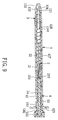
- the eighth preferred embodiment of a disposable syringe according to this invention is similar to the seventh preferred embodiment in construction, and is adapted for injecting medication of a general volume, such as 3 ml, 5 ml, or more.
- the larger rear segment 424 of the intermediate surrounding wall 42 of the tubular plunger 4 includes front andrearwall segments 4241, 4242 which are disposed proximate to the front and rear opened end walls 421, 422, respectively, and which have smaller and larger outer peripheral surfaces, respectively.
- the plunger 4 further includes a plurality of rib fins 46 which are formed on the smaller outer peripheral surface of the front wall segment 4241 and which are flush with the larger outer peripheral surface of the rear wall segment 4242 so as to guide movement of the plunger 4 relative to the larger-diameter portion 11 of the inner surrounding barrel surface 13 while minimizing frictional force therebetween.
- the smaller front segment 423 and the coupling member 51 respectively have an annular protrusion 427a and an annular groove 512a which engage each other to provide the second frictional force.
- the coupling member 51 further has a tapered rear portion 517 opposite to the engaging recess 516 so as to establish fluid-tight engagement with the smaller front segment 423.
- the sealing member 55 is formed integrally with the coupling member 51 and is disposed between the tapered rear portion 517 and the annular groove 512a.
- the coupling member 51 When the surrounding retainedportion (the annular groove 512a) is released from the intermediate surrounding wall 42 (the annular protrusion 427a), the coupling member 51 is received in the accommodation chamber 41 at the front wall segment 4241, and is held in fluid-tight contact with the front wall segment 4241, thereby facilitating sliding of the coupling member 51, as well as the needle assembly 2, to the retracted position.
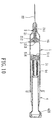
- the ninth preferred embodiment of a disposable syringe according to this invention is similar to the eighth preferred embodiment in construction, but is adapted for injecting medication of an extremely small injection volume, such as 1ml.
- the sealing member 55 is formed integrally with the coupling member 51, is made from a deformable material, and surrounds the anchored portion 514.
- the coupling member 51 has an annular front edge 518 which is slidable on and is in fluid-tight engagement with the larger-diameter portion 11 of the barrel 1 so as to serve as the seal ring 43 in the previous preferred embodiment.
- the annular front edge 518 is deformed and converged to be retracted into the accommodation chamber 41.
- a sealing unit 7 is further disposed to be in fluid-tight engagement with the friction diminishing region 122, and is spaced apart from the shoulder abutment 124 to define a space of triggering action for retraction of the needle assembly 2.
- the sealing unit 7 includes an elastomeric plug 71 and a ring plate 72 abutting against each other.
- the tubular grip member 3 is formed with a deformable sealing portion 32 which is in fluid-tight engagement with the gripped portion 212 of the needle seat 21 so as to form a fluid-tight compressible chamber 73.
- the compressible chamber 73 is filled with a fluid.
- the front hub portion 211 of the needle seat 21 is disposed to abut against the sealing unit 7, and has a plurality of through holes 214 formed therethrough so as to be in fluid communication with the compressible chamber 73.
- the eleventh, twelfth, thirteenth and fourteenth preferred embodiments of a disposable syringe according to this invention are respectively similar to the ninth, second, fourth and sixth preferred embodiments in construction.
- the disposable syringe further comprises a sealing unit 7 which is the same as that of the tenth preferred embodiment, and which is disposed to be in fluid-tight engagement with the friction diminishing region 122.
Landscapes
- Health & Medical Sciences (AREA)
- Engineering & Computer Science (AREA)
- Heart & Thoracic Surgery (AREA)
- Vascular Medicine (AREA)
- Anesthesiology (AREA)
- Biomedical Technology (AREA)
- Environmental & Geological Engineering (AREA)
- Hematology (AREA)
- Life Sciences & Earth Sciences (AREA)
- Animal Behavior & Ethology (AREA)
- General Health & Medical Sciences (AREA)
- Public Health (AREA)
- Veterinary Medicine (AREA)
- Infusion, Injection, And Reservoir Apparatuses (AREA)
Priority Applications (3)
| Application Number | Priority Date | Filing Date | Title |
|---|---|---|---|
| AT04254805T ATE424229T1 (de) | 2004-08-10 | 2004-08-10 | Einweg spritze mit einziehbarer nadel |
| EP04254805A EP1625865B1 (de) | 2004-08-10 | 2004-08-10 | Einweg Spritze mit einziehbarer Nadel |
| DE602004019775T DE602004019775D1 (de) | 2004-08-10 | 2004-08-10 | Einweg Spritze mit einziehbarer Nadel |
Applications Claiming Priority (1)
| Application Number | Priority Date | Filing Date | Title |
|---|---|---|---|
| EP04254805A EP1625865B1 (de) | 2004-08-10 | 2004-08-10 | Einweg Spritze mit einziehbarer Nadel |
Publications (2)
| Publication Number | Publication Date |
|---|---|
| EP1625865A1 true EP1625865A1 (de) | 2006-02-15 |
| EP1625865B1 EP1625865B1 (de) | 2009-03-04 |
Family
ID=34930549
Family Applications (1)
| Application Number | Title | Priority Date | Filing Date |
|---|---|---|---|
| EP04254805A Expired - Lifetime EP1625865B1 (de) | 2004-08-10 | 2004-08-10 | Einweg Spritze mit einziehbarer Nadel |
Country Status (3)
| Country | Link |
|---|---|
| EP (1) | EP1625865B1 (de) |
| AT (1) | ATE424229T1 (de) |
| DE (1) | DE602004019775D1 (de) |
Cited By (2)
| Publication number | Priority date | Publication date | Assignee | Title |
|---|---|---|---|---|
| EP2279769A4 (de) * | 2008-05-08 | 2012-09-19 | Shantou Wealy Medical Instr Co Ltd | Selbstzerstörende sicherheitsspritze zum einmaligen gebrauch ohne flüssigkeitsrückstände |
| AU2020200304A1 (en) * | 2019-12-16 | 2021-07-01 | Guangdong Hongshan Medical Device Technology Co., Ltd | Novel composite safety self-destructing syringe |
Families Citing this family (1)
| Publication number | Priority date | Publication date | Assignee | Title |
|---|---|---|---|---|
| TWI556807B (zh) * | 2010-05-04 | 2016-11-11 | Unitract Syringe Pty Ltd | Syringe syringe adapter and syringe assembly |
Citations (4)
| Publication number | Priority date | Publication date | Assignee | Title |
|---|---|---|---|---|
| US5084018A (en) * | 1989-08-14 | 1992-01-28 | Tsao Chien Hua | Safety syringe |
| US5211628A (en) * | 1991-09-30 | 1993-05-18 | Marshall John M | Syringe with automatic retracting needle |
| US20030236501A1 (en) | 1998-09-04 | 2003-12-25 | Donnan Jeremy Francis | Retractable needle syringe including a sheath and an intravenous adapter |
| EP1421962A1 (de) | 2002-11-20 | 2004-05-26 | Ming-Jeng Shue | Einwegspritze |
-
2004
- 2004-08-10 AT AT04254805T patent/ATE424229T1/de not_active IP Right Cessation
- 2004-08-10 EP EP04254805A patent/EP1625865B1/de not_active Expired - Lifetime
- 2004-08-10 DE DE602004019775T patent/DE602004019775D1/de not_active Expired - Lifetime
Patent Citations (4)
| Publication number | Priority date | Publication date | Assignee | Title |
|---|---|---|---|---|
| US5084018A (en) * | 1989-08-14 | 1992-01-28 | Tsao Chien Hua | Safety syringe |
| US5211628A (en) * | 1991-09-30 | 1993-05-18 | Marshall John M | Syringe with automatic retracting needle |
| US20030236501A1 (en) | 1998-09-04 | 2003-12-25 | Donnan Jeremy Francis | Retractable needle syringe including a sheath and an intravenous adapter |
| EP1421962A1 (de) | 2002-11-20 | 2004-05-26 | Ming-Jeng Shue | Einwegspritze |
Cited By (2)
| Publication number | Priority date | Publication date | Assignee | Title |
|---|---|---|---|---|
| EP2279769A4 (de) * | 2008-05-08 | 2012-09-19 | Shantou Wealy Medical Instr Co Ltd | Selbstzerstörende sicherheitsspritze zum einmaligen gebrauch ohne flüssigkeitsrückstände |
| AU2020200304A1 (en) * | 2019-12-16 | 2021-07-01 | Guangdong Hongshan Medical Device Technology Co., Ltd | Novel composite safety self-destructing syringe |
Also Published As
| Publication number | Publication date |
|---|---|
| EP1625865B1 (de) | 2009-03-04 |
| DE602004019775D1 (de) | 2009-04-16 |
| ATE424229T1 (de) | 2009-03-15 |
Similar Documents
| Publication | Publication Date | Title |
|---|---|---|
| US7425205B2 (en) | Disposable syringe with a retractable needle | |
| US6743199B2 (en) | Disposable syringe | |
| US6592555B1 (en) | Syringe device | |
| US5882342A (en) | Safety medical syringe with retractable needle | |
| US6206857B1 (en) | Syringe with needle retraction arrangement | |
| US9381309B2 (en) | Frontal attachment device for syringe with pinch-activated retraction | |
| SE467521B (sv) | Foerfylld spruta | |
| AU2003248300B2 (en) | Disposable syringe | |
| HUT76899A (en) | Low drag syringe and cartridge | |
| US20040153037A1 (en) | Hypodermic syringe having plunger pull-out stopping structure | |
| US7192418B2 (en) | Disposable syringe | |
| US20050261627A1 (en) | Single-use syringe | |
| EP1625865B1 (de) | Einweg Spritze mit einziehbarer Nadel | |
| US20080119786A1 (en) | Hypodermic Syringe | |
| EP1421962B1 (de) | Einwegspritze | |
| US20070005015A1 (en) | Disposable syringe | |
| EP1556109A2 (de) | Mittels vakuum selbsteinziehbare sicherheitsspritze | |
| GB2441430A (en) | Safety hypodermic syringe | |
| AU2003101038A4 (en) | Safety Fluid Injecting/Sampling Apparatus | |
| US20130079713A1 (en) | Automatic retractable safety syringe | |
| EP0774268A1 (de) | Einwegspritze | |
| EP1514568A1 (de) | Einwegspritze | |
| CN101171045A (zh) | 可缩回的针装置 | |
| GB2418863A (en) | A safety syringe with a breakable plunger | |
| EP1629858A1 (de) | Einwegspritze |
Legal Events
| Date | Code | Title | Description |
|---|---|---|---|
| PUAI | Public reference made under article 153(3) epc to a published international application that has entered the european phase |
Free format text: ORIGINAL CODE: 0009012 |
|
| AK | Designated contracting states |
Kind code of ref document: A1 Designated state(s): AT BE BG CH CY CZ DE DK EE ES FI FR GB GR HU IE IT LI LU MC NL PL PT RO SE SI SK TR |
|
| AX | Request for extension of the european patent |
Extension state: AL HR LT LV MK |
|
| 17P | Request for examination filed |
Effective date: 20060510 |
|
| AKX | Designation fees paid |
Designated state(s): AT BE BG CH CY CZ DE DK EE ES FI FR GB GR HU IE IT LI LU MC NL PL PT RO SE SI SK TR |
|
| 17Q | First examination report despatched |
Effective date: 20061115 |
|
| GRAP | Despatch of communication of intention to grant a patent |
Free format text: ORIGINAL CODE: EPIDOSNIGR1 |
|
| GRAS | Grant fee paid |
Free format text: ORIGINAL CODE: EPIDOSNIGR3 |
|
| GRAA | (expected) grant |
Free format text: ORIGINAL CODE: 0009210 |
|
| AK | Designated contracting states |
Kind code of ref document: B1 Designated state(s): AT BE BG CH CY CZ DE DK EE ES FI FR GB GR HU IE IT LI LU MC NL PL PT RO SE SI SK TR |
|
| REG | Reference to a national code |
Ref country code: GB Ref legal event code: FG4D |
|
| REG | Reference to a national code |
Ref country code: CH Ref legal event code: EP |
|
| REG | Reference to a national code |
Ref country code: IE Ref legal event code: FG4D |
|
| REF | Corresponds to: |
Ref document number: 602004019775 Country of ref document: DE Date of ref document: 20090416 Kind code of ref document: P |
|
| REG | Reference to a national code |
Ref country code: SE Ref legal event code: TRGR |
|
| PG25 | Lapsed in a contracting state [announced via postgrant information from national office to epo] |
Ref country code: FI Free format text: LAPSE BECAUSE OF FAILURE TO SUBMIT A TRANSLATION OF THE DESCRIPTION OR TO PAY THE FEE WITHIN THE PRESCRIBED TIME-LIMIT Effective date: 20090304 Ref country code: SI Free format text: LAPSE BECAUSE OF FAILURE TO SUBMIT A TRANSLATION OF THE DESCRIPTION OR TO PAY THE FEE WITHIN THE PRESCRIBED TIME-LIMIT Effective date: 20090304 Ref country code: NL Free format text: LAPSE BECAUSE OF FAILURE TO SUBMIT A TRANSLATION OF THE DESCRIPTION OR TO PAY THE FEE WITHIN THE PRESCRIBED TIME-LIMIT Effective date: 20090304 |
|
| NLV1 | Nl: lapsed or annulled due to failure to fulfill the requirements of art. 29p and 29m of the patents act | ||
| PG25 | Lapsed in a contracting state [announced via postgrant information from national office to epo] |
Ref country code: AT Free format text: LAPSE BECAUSE OF FAILURE TO SUBMIT A TRANSLATION OF THE DESCRIPTION OR TO PAY THE FEE WITHIN THE PRESCRIBED TIME-LIMIT Effective date: 20090304 Ref country code: PL Free format text: LAPSE BECAUSE OF FAILURE TO SUBMIT A TRANSLATION OF THE DESCRIPTION OR TO PAY THE FEE WITHIN THE PRESCRIBED TIME-LIMIT Effective date: 20090304 |
|
| PG25 | Lapsed in a contracting state [announced via postgrant information from national office to epo] |
Ref country code: BE Free format text: LAPSE BECAUSE OF FAILURE TO SUBMIT A TRANSLATION OF THE DESCRIPTION OR TO PAY THE FEE WITHIN THE PRESCRIBED TIME-LIMIT Effective date: 20090304 |
|
| PG25 | Lapsed in a contracting state [announced via postgrant information from national office to epo] |
Ref country code: EE Free format text: LAPSE BECAUSE OF FAILURE TO SUBMIT A TRANSLATION OF THE DESCRIPTION OR TO PAY THE FEE WITHIN THE PRESCRIBED TIME-LIMIT Effective date: 20090304 Ref country code: ES Free format text: LAPSE BECAUSE OF FAILURE TO SUBMIT A TRANSLATION OF THE DESCRIPTION OR TO PAY THE FEE WITHIN THE PRESCRIBED TIME-LIMIT Effective date: 20090615 Ref country code: PT Free format text: LAPSE BECAUSE OF FAILURE TO SUBMIT A TRANSLATION OF THE DESCRIPTION OR TO PAY THE FEE WITHIN THE PRESCRIBED TIME-LIMIT Effective date: 20090818 Ref country code: CZ Free format text: LAPSE BECAUSE OF FAILURE TO SUBMIT A TRANSLATION OF THE DESCRIPTION OR TO PAY THE FEE WITHIN THE PRESCRIBED TIME-LIMIT Effective date: 20090304 |
|
| PG25 | Lapsed in a contracting state [announced via postgrant information from national office to epo] |
Ref country code: RO Free format text: LAPSE BECAUSE OF FAILURE TO SUBMIT A TRANSLATION OF THE DESCRIPTION OR TO PAY THE FEE WITHIN THE PRESCRIBED TIME-LIMIT Effective date: 20090304 Ref country code: SK Free format text: LAPSE BECAUSE OF FAILURE TO SUBMIT A TRANSLATION OF THE DESCRIPTION OR TO PAY THE FEE WITHIN THE PRESCRIBED TIME-LIMIT Effective date: 20090304 |
|
| PLBE | No opposition filed within time limit |
Free format text: ORIGINAL CODE: 0009261 |
|
| STAA | Information on the status of an ep patent application or granted ep patent |
Free format text: STATUS: NO OPPOSITION FILED WITHIN TIME LIMIT |
|
| PG25 | Lapsed in a contracting state [announced via postgrant information from national office to epo] |
Ref country code: DK Free format text: LAPSE BECAUSE OF FAILURE TO SUBMIT A TRANSLATION OF THE DESCRIPTION OR TO PAY THE FEE WITHIN THE PRESCRIBED TIME-LIMIT Effective date: 20090304 Ref country code: BG Free format text: LAPSE BECAUSE OF FAILURE TO SUBMIT A TRANSLATION OF THE DESCRIPTION OR TO PAY THE FEE WITHIN THE PRESCRIBED TIME-LIMIT Effective date: 20090604 |
|
| 26N | No opposition filed |
Effective date: 20091207 |
|
| PG25 | Lapsed in a contracting state [announced via postgrant information from national office to epo] |
Ref country code: MC Free format text: LAPSE BECAUSE OF NON-PAYMENT OF DUE FEES Effective date: 20090831 |
|
| REG | Reference to a national code |
Ref country code: CH Ref legal event code: PL |
|
| PG25 | Lapsed in a contracting state [announced via postgrant information from national office to epo] |
Ref country code: CH Free format text: LAPSE BECAUSE OF NON-PAYMENT OF DUE FEES Effective date: 20090831 Ref country code: LI Free format text: LAPSE BECAUSE OF NON-PAYMENT OF DUE FEES Effective date: 20090831 |
|
| PG25 | Lapsed in a contracting state [announced via postgrant information from national office to epo] |
Ref country code: IE Free format text: LAPSE BECAUSE OF NON-PAYMENT OF DUE FEES Effective date: 20090810 |
|
| PG25 | Lapsed in a contracting state [announced via postgrant information from national office to epo] |
Ref country code: GR Free format text: LAPSE BECAUSE OF FAILURE TO SUBMIT A TRANSLATION OF THE DESCRIPTION OR TO PAY THE FEE WITHIN THE PRESCRIBED TIME-LIMIT Effective date: 20090605 |
|
| PG25 | Lapsed in a contracting state [announced via postgrant information from national office to epo] |
Ref country code: LU Free format text: LAPSE BECAUSE OF NON-PAYMENT OF DUE FEES Effective date: 20090810 |
|
| PG25 | Lapsed in a contracting state [announced via postgrant information from national office to epo] |
Ref country code: HU Free format text: LAPSE BECAUSE OF FAILURE TO SUBMIT A TRANSLATION OF THE DESCRIPTION OR TO PAY THE FEE WITHIN THE PRESCRIBED TIME-LIMIT Effective date: 20090905 |
|
| PG25 | Lapsed in a contracting state [announced via postgrant information from national office to epo] |
Ref country code: TR Free format text: LAPSE BECAUSE OF FAILURE TO SUBMIT A TRANSLATION OF THE DESCRIPTION OR TO PAY THE FEE WITHIN THE PRESCRIBED TIME-LIMIT Effective date: 20090304 |
|
| PG25 | Lapsed in a contracting state [announced via postgrant information from national office to epo] |
Ref country code: CY Free format text: LAPSE BECAUSE OF FAILURE TO SUBMIT A TRANSLATION OF THE DESCRIPTION OR TO PAY THE FEE WITHIN THE PRESCRIBED TIME-LIMIT Effective date: 20090304 |
|
| REG | Reference to a national code |
Ref country code: FR Ref legal event code: PLFP Year of fee payment: 13 |
|
| REG | Reference to a national code |
Ref country code: FR Ref legal event code: PLFP Year of fee payment: 14 |
|
| REG | Reference to a national code |
Ref country code: FR Ref legal event code: PLFP Year of fee payment: 15 |
|
| PGFP | Annual fee paid to national office [announced via postgrant information from national office to epo] |
Ref country code: FR Payment date: 20180626 Year of fee payment: 15 |
|
| PGFP | Annual fee paid to national office [announced via postgrant information from national office to epo] |
Ref country code: SE Payment date: 20180626 Year of fee payment: 15 |
|
| PGFP | Annual fee paid to national office [announced via postgrant information from national office to epo] |
Ref country code: DE Payment date: 20190729 Year of fee payment: 16 Ref country code: IT Payment date: 20190822 Year of fee payment: 16 |
|
| REG | Reference to a national code |
Ref country code: SE Ref legal event code: EUG |
|
| PG25 | Lapsed in a contracting state [announced via postgrant information from national office to epo] |
Ref country code: SE Free format text: LAPSE BECAUSE OF NON-PAYMENT OF DUE FEES Effective date: 20190811 |
|
| PG25 | Lapsed in a contracting state [announced via postgrant information from national office to epo] |
Ref country code: FR Free format text: LAPSE BECAUSE OF NON-PAYMENT OF DUE FEES Effective date: 20190831 |
|
| PGFP | Annual fee paid to national office [announced via postgrant information from national office to epo] |
Ref country code: GB Payment date: 20200708 Year of fee payment: 17 |
|
| REG | Reference to a national code |
Ref country code: DE Ref legal event code: R119 Ref document number: 602004019775 Country of ref document: DE |
|
| PG25 | Lapsed in a contracting state [announced via postgrant information from national office to epo] |
Ref country code: IT Free format text: LAPSE BECAUSE OF NON-PAYMENT OF DUE FEES Effective date: 20200810 Ref country code: DE Free format text: LAPSE BECAUSE OF NON-PAYMENT OF DUE FEES Effective date: 20210302 |
|
| GBPC | Gb: european patent ceased through non-payment of renewal fee |
Effective date: 20210810 |
|
| PG25 | Lapsed in a contracting state [announced via postgrant information from national office to epo] |
Ref country code: GB Free format text: LAPSE BECAUSE OF NON-PAYMENT OF DUE FEES Effective date: 20210810 |