EP1625925A2 - Formteil und Verfahren zur Herstellung - Google Patents
Formteil und Verfahren zur Herstellung Download PDFInfo
- Publication number
- EP1625925A2 EP1625925A2 EP05013521A EP05013521A EP1625925A2 EP 1625925 A2 EP1625925 A2 EP 1625925A2 EP 05013521 A EP05013521 A EP 05013521A EP 05013521 A EP05013521 A EP 05013521A EP 1625925 A2 EP1625925 A2 EP 1625925A2
- Authority
- EP
- European Patent Office
- Prior art keywords
- trim element
- trim
- moulded
- mould
- recess
- Prior art date
- Legal status (The legal status is an assumption and is not a legal conclusion. Google has not performed a legal analysis and makes no representation as to the accuracy of the status listed.)
- Withdrawn
Links
- 238000004519 manufacturing process Methods 0.000 title claims abstract description 23
- 238000000034 method Methods 0.000 title claims description 21
- 238000002347 injection Methods 0.000 claims abstract description 17
- 239000007924 injection Substances 0.000 claims abstract description 17
- 239000000463 material Substances 0.000 claims abstract description 14
- 229920001169 thermoplastic Polymers 0.000 claims abstract description 10
- 239000004416 thermosoftening plastic Substances 0.000 claims abstract description 10
- 230000002093 peripheral effect Effects 0.000 claims description 17
- 238000000465 moulding Methods 0.000 claims description 15
- 239000000758 substrate Substances 0.000 claims description 9
- 229920002554 vinyl polymer Polymers 0.000 claims description 4
- 239000010410 layer Substances 0.000 claims 5
- 239000011241 protective layer Substances 0.000 claims 1
- 229920003023 plastic Polymers 0.000 description 8
- 239000004033 plastic Substances 0.000 description 8
- 239000011888 foil Substances 0.000 description 7
- 239000000853 adhesive Substances 0.000 description 5
- 230000001070 adhesive effect Effects 0.000 description 5
- 239000002184 metal Substances 0.000 description 5
- 239000011248 coating agent Substances 0.000 description 4
- 238000000576 coating method Methods 0.000 description 4
- 238000001746 injection moulding Methods 0.000 description 4
- 238000002372 labelling Methods 0.000 description 4
- 239000002033 PVDF binder Substances 0.000 description 3
- 239000002991 molded plastic Substances 0.000 description 3
- 229920003229 poly(methyl methacrylate) Polymers 0.000 description 3
- 239000004926 polymethyl methacrylate Substances 0.000 description 3
- 229920002981 polyvinylidene fluoride Polymers 0.000 description 3
- 238000006748 scratching Methods 0.000 description 3
- 230000002393 scratching effect Effects 0.000 description 3
- 239000012815 thermoplastic material Substances 0.000 description 3
- 238000005299 abrasion Methods 0.000 description 2
- 239000004743 Polypropylene Substances 0.000 description 1
- 238000000071 blow moulding Methods 0.000 description 1
- 238000012986 modification Methods 0.000 description 1
- 230000004048 modification Effects 0.000 description 1
- 239000003973 paint Substances 0.000 description 1
- -1 polypropylene Polymers 0.000 description 1
- 229920001155 polypropylene Polymers 0.000 description 1
- 230000001681 protective effect Effects 0.000 description 1
- 239000007787 solid Substances 0.000 description 1
- 229920002397 thermoplastic olefin Polymers 0.000 description 1
- 230000000007 visual effect Effects 0.000 description 1
Images

Classifications
-
- B—PERFORMING OPERATIONS; TRANSPORTING
- B29—WORKING OF PLASTICS; WORKING OF SUBSTANCES IN A PLASTIC STATE IN GENERAL
- B29C—SHAPING OR JOINING OF PLASTICS; SHAPING OF MATERIAL IN A PLASTIC STATE, NOT OTHERWISE PROVIDED FOR; AFTER-TREATMENT OF THE SHAPED PRODUCTS, e.g. REPAIRING
- B29C45/00—Injection moulding, i.e. forcing the required volume of moulding material through a nozzle into a closed mould; Apparatus therefor
- B29C45/14—Injection moulding, i.e. forcing the required volume of moulding material through a nozzle into a closed mould; Apparatus therefor incorporating preformed parts or layers, e.g. injection moulding around inserts or for coating articles
- B29C45/1418—Injection moulding, i.e. forcing the required volume of moulding material through a nozzle into a closed mould; Apparatus therefor incorporating preformed parts or layers, e.g. injection moulding around inserts or for coating articles the inserts being deformed or preformed, e.g. by the injection pressure
-
- B—PERFORMING OPERATIONS; TRANSPORTING
- B29—WORKING OF PLASTICS; WORKING OF SUBSTANCES IN A PLASTIC STATE IN GENERAL
- B29C—SHAPING OR JOINING OF PLASTICS; SHAPING OF MATERIAL IN A PLASTIC STATE, NOT OTHERWISE PROVIDED FOR; AFTER-TREATMENT OF THE SHAPED PRODUCTS, e.g. REPAIRING
- B29C45/00—Injection moulding, i.e. forcing the required volume of moulding material through a nozzle into a closed mould; Apparatus therefor
- B29C45/14—Injection moulding, i.e. forcing the required volume of moulding material through a nozzle into a closed mould; Apparatus therefor incorporating preformed parts or layers, e.g. injection moulding around inserts or for coating articles
- B29C45/14065—Positioning or centering articles in the mould
-
- B—PERFORMING OPERATIONS; TRANSPORTING
- B29—WORKING OF PLASTICS; WORKING OF SUBSTANCES IN A PLASTIC STATE IN GENERAL
- B29C—SHAPING OR JOINING OF PLASTICS; SHAPING OF MATERIAL IN A PLASTIC STATE, NOT OTHERWISE PROVIDED FOR; AFTER-TREATMENT OF THE SHAPED PRODUCTS, e.g. REPAIRING
- B29C45/00—Injection moulding, i.e. forcing the required volume of moulding material through a nozzle into a closed mould; Apparatus therefor
- B29C45/14—Injection moulding, i.e. forcing the required volume of moulding material through a nozzle into a closed mould; Apparatus therefor incorporating preformed parts or layers, e.g. injection moulding around inserts or for coating articles
- B29C45/14688—Coating articles provided with a decoration
-
- B—PERFORMING OPERATIONS; TRANSPORTING
- B29—WORKING OF PLASTICS; WORKING OF SUBSTANCES IN A PLASTIC STATE IN GENERAL
- B29C—SHAPING OR JOINING OF PLASTICS; SHAPING OF MATERIAL IN A PLASTIC STATE, NOT OTHERWISE PROVIDED FOR; AFTER-TREATMENT OF THE SHAPED PRODUCTS, e.g. REPAIRING
- B29C45/00—Injection moulding, i.e. forcing the required volume of moulding material through a nozzle into a closed mould; Apparatus therefor
- B29C45/14—Injection moulding, i.e. forcing the required volume of moulding material through a nozzle into a closed mould; Apparatus therefor incorporating preformed parts or layers, e.g. injection moulding around inserts or for coating articles
- B29C45/14778—Injection moulding, i.e. forcing the required volume of moulding material through a nozzle into a closed mould; Apparatus therefor incorporating preformed parts or layers, e.g. injection moulding around inserts or for coating articles the article consisting of a material with particular properties, e.g. porous, brittle
- B29C45/14811—Multilayered articles
-
- B—PERFORMING OPERATIONS; TRANSPORTING
- B60—VEHICLES IN GENERAL
- B60R—VEHICLES, VEHICLE FITTINGS, OR VEHICLE PARTS, NOT OTHERWISE PROVIDED FOR
- B60R13/00—Elements for body-finishing, identifying, or decorating; Arrangements or adaptations for advertising purposes
-
- B—PERFORMING OPERATIONS; TRANSPORTING
- B60—VEHICLES IN GENERAL
- B60R—VEHICLES, VEHICLE FITTINGS, OR VEHICLE PARTS, NOT OTHERWISE PROVIDED FOR
- B60R13/00—Elements for body-finishing, identifying, or decorating; Arrangements or adaptations for advertising purposes
- B60R13/005—Manufacturers' emblems, name plates, bonnet ornaments, mascots or the like; Mounting means therefor
-
- B—PERFORMING OPERATIONS; TRANSPORTING
- B60—VEHICLES IN GENERAL
- B60R—VEHICLES, VEHICLE FITTINGS, OR VEHICLE PARTS, NOT OTHERWISE PROVIDED FOR
- B60R13/00—Elements for body-finishing, identifying, or decorating; Arrangements or adaptations for advertising purposes
- B60R13/02—Internal Trim mouldings ; Internal Ledges; Wall liners for passenger compartments; Roof liners
-
- B—PERFORMING OPERATIONS; TRANSPORTING
- B60—VEHICLES IN GENERAL
- B60R—VEHICLES, VEHICLE FITTINGS, OR VEHICLE PARTS, NOT OTHERWISE PROVIDED FOR
- B60R13/00—Elements for body-finishing, identifying, or decorating; Arrangements or adaptations for advertising purposes
- B60R13/04—External Ornamental or guard strips; Ornamental inscriptive devices thereon
-
- B—PERFORMING OPERATIONS; TRANSPORTING
- B29—WORKING OF PLASTICS; WORKING OF SUBSTANCES IN A PLASTIC STATE IN GENERAL
- B29C—SHAPING OR JOINING OF PLASTICS; SHAPING OF MATERIAL IN A PLASTIC STATE, NOT OTHERWISE PROVIDED FOR; AFTER-TREATMENT OF THE SHAPED PRODUCTS, e.g. REPAIRING
- B29C45/00—Injection moulding, i.e. forcing the required volume of moulding material through a nozzle into a closed mould; Apparatus therefor
- B29C45/14—Injection moulding, i.e. forcing the required volume of moulding material through a nozzle into a closed mould; Apparatus therefor incorporating preformed parts or layers, e.g. injection moulding around inserts or for coating articles
- B29C45/14065—Positioning or centering articles in the mould
- B29C2045/14155—Positioning or centering articles in the mould using vacuum or suction
-
- B—PERFORMING OPERATIONS; TRANSPORTING
- B29—WORKING OF PLASTICS; WORKING OF SUBSTANCES IN A PLASTIC STATE IN GENERAL
- B29C—SHAPING OR JOINING OF PLASTICS; SHAPING OF MATERIAL IN A PLASTIC STATE, NOT OTHERWISE PROVIDED FOR; AFTER-TREATMENT OF THE SHAPED PRODUCTS, e.g. REPAIRING
- B29C45/00—Injection moulding, i.e. forcing the required volume of moulding material through a nozzle into a closed mould; Apparatus therefor
- B29C45/14—Injection moulding, i.e. forcing the required volume of moulding material through a nozzle into a closed mould; Apparatus therefor incorporating preformed parts or layers, e.g. injection moulding around inserts or for coating articles
- B29C2045/1486—Details, accessories and auxiliary operations
- B29C2045/14901—Coating a sheet-like insert smaller than the dimensions of the adjacent mould wall
- B29C2045/14918—Coating a sheet-like insert smaller than the dimensions of the adjacent mould wall in-mould-labelling
-
- B—PERFORMING OPERATIONS; TRANSPORTING
- B29—WORKING OF PLASTICS; WORKING OF SUBSTANCES IN A PLASTIC STATE IN GENERAL
- B29C—SHAPING OR JOINING OF PLASTICS; SHAPING OF MATERIAL IN A PLASTIC STATE, NOT OTHERWISE PROVIDED FOR; AFTER-TREATMENT OF THE SHAPED PRODUCTS, e.g. REPAIRING
- B29C45/00—Injection moulding, i.e. forcing the required volume of moulding material through a nozzle into a closed mould; Apparatus therefor
- B29C45/17—Component parts, details or accessories; Auxiliary operations
- B29C45/26—Moulds
- B29C2045/2695—Moulds injecting articles with varying wall thickness, e.g. for making a tear line
-
- B—PERFORMING OPERATIONS; TRANSPORTING
- B29—WORKING OF PLASTICS; WORKING OF SUBSTANCES IN A PLASTIC STATE IN GENERAL
- B29C—SHAPING OR JOINING OF PLASTICS; SHAPING OF MATERIAL IN A PLASTIC STATE, NOT OTHERWISE PROVIDED FOR; AFTER-TREATMENT OF THE SHAPED PRODUCTS, e.g. REPAIRING
- B29C45/00—Injection moulding, i.e. forcing the required volume of moulding material through a nozzle into a closed mould; Apparatus therefor
- B29C45/17—Component parts, details or accessories; Auxiliary operations
- B29C45/26—Moulds
- B29C45/2673—Moulds with exchangeable mould parts, e.g. cassette moulds
-
- B—PERFORMING OPERATIONS; TRANSPORTING
- B29—WORKING OF PLASTICS; WORKING OF SUBSTANCES IN A PLASTIC STATE IN GENERAL
- B29C—SHAPING OR JOINING OF PLASTICS; SHAPING OF MATERIAL IN A PLASTIC STATE, NOT OTHERWISE PROVIDED FOR; AFTER-TREATMENT OF THE SHAPED PRODUCTS, e.g. REPAIRING
- B29C45/00—Injection moulding, i.e. forcing the required volume of moulding material through a nozzle into a closed mould; Apparatus therefor
- B29C45/17—Component parts, details or accessories; Auxiliary operations
- B29C45/26—Moulds
- B29C45/37—Mould cavity walls, i.e. the inner surface forming the mould cavity, e.g. linings
-
- B—PERFORMING OPERATIONS; TRANSPORTING
- B29—WORKING OF PLASTICS; WORKING OF SUBSTANCES IN A PLASTIC STATE IN GENERAL
- B29K—INDEXING SCHEME ASSOCIATED WITH SUBCLASSES B29B, B29C OR B29D, RELATING TO MOULDING MATERIALS OR TO MATERIALS FOR MOULDS, REINFORCEMENTS, FILLERS OR PREFORMED PARTS, e.g. INSERTS
- B29K2705/00—Use of metals, their alloys or their compounds, for preformed parts, e.g. for inserts
-
- B—PERFORMING OPERATIONS; TRANSPORTING
- B29—WORKING OF PLASTICS; WORKING OF SUBSTANCES IN A PLASTIC STATE IN GENERAL
- B29K—INDEXING SCHEME ASSOCIATED WITH SUBCLASSES B29B, B29C OR B29D, RELATING TO MOULDING MATERIALS OR TO MATERIALS FOR MOULDS, REINFORCEMENTS, FILLERS OR PREFORMED PARTS, e.g. INSERTS
- B29K2715/00—Condition, form or state of preformed parts, e.g. inserts
- B29K2715/006—Glues or adhesives, e.g. hot melts or thermofusible adhesives
-
- B—PERFORMING OPERATIONS; TRANSPORTING
- B29—WORKING OF PLASTICS; WORKING OF SUBSTANCES IN A PLASTIC STATE IN GENERAL
- B29K—INDEXING SCHEME ASSOCIATED WITH SUBCLASSES B29B, B29C OR B29D, RELATING TO MOULDING MATERIALS OR TO MATERIALS FOR MOULDS, REINFORCEMENTS, FILLERS OR PREFORMED PARTS, e.g. INSERTS
- B29K2995/00—Properties of moulding materials, reinforcements, fillers, preformed parts or moulds
- B29K2995/0018—Properties of moulding materials, reinforcements, fillers, preformed parts or moulds having particular optical properties, e.g. fluorescent or phosphorescent
- B29K2995/002—Coloured
-
- B—PERFORMING OPERATIONS; TRANSPORTING
- B29—WORKING OF PLASTICS; WORKING OF SUBSTANCES IN A PLASTIC STATE IN GENERAL
- B29L—INDEXING SCHEME ASSOCIATED WITH SUBCLASS B29C, RELATING TO PARTICULAR ARTICLES
- B29L2031/00—Other particular articles
- B29L2031/30—Vehicles, e.g. ships or aircraft, or body parts thereof
- B29L2031/3005—Body finishings
- B29L2031/302—Trim strips
-
- B—PERFORMING OPERATIONS; TRANSPORTING
- B60—VEHICLES IN GENERAL
- B60R—VEHICLES, VEHICLE FITTINGS, OR VEHICLE PARTS, NOT OTHERWISE PROVIDED FOR
- B60R13/00—Elements for body-finishing, identifying, or decorating; Arrangements or adaptations for advertising purposes
- B60R13/02—Internal Trim mouldings ; Internal Ledges; Wall liners for passenger compartments; Roof liners
- B60R13/0237—Side or rear panels
- B60R13/0243—Doors
Definitions
- the present invention relates to a moulded article and a method of manufacture.
- the invention relates to an injection moulded plastics article having a decorative trim element attached thereto, and a method of manufacturing the article.
- the injection moulded article of the present invention may be designed for use in many different applications.
- the article may be intended for use in a motor vehicle, and may comprise an interior panel, a radiator grill or similar.
- One specific example described in detail below relates to a scuff plate that is designed to fit into the bottom part of a car door opening, to protect the paintwork of the car from scratching by the feet of passengers entering and leaving the car. It should be understood however that the invention is not intended to be limited to that particular product or to a method of manufacturing that product.
- a moulded plastics article such as those described above to support a decorative trim element such as a polished metal plate, which may typically carry the maker's name or some other graphic or logo.
- the plastic part is manufactured by injection moulding and the trim element is then attached to the moulded plastic part, for example using an adhesive.
- this requires a number of additional manufacturing processes, including manufacturing the trim element and then attaching that element to the moulded part, which increase the production costs.
- the present invention is based on the realisation that a similar in-mould process can be used in the production of an injection moulded product having a decorative trim element.
- a method of manufacturing a moulded article including placing a decorative trim element in a mould and injecting a thermoplastics material into the mould to form an injection moulded element having the decorative trim element attached thereto.
- the method of the present invention makes it possible to attach a trim element to the moulded product during the moulding process, so avoiding the need for a separate manufacturing process and thereby reducing the manufacturing costs.
- the trim element can consist of a simple inexpensive item, such as a laminated foil, rather than a polished metal plate. Component costs can also therefore be reduced.
- the method includes applying a vacuum to retain the trim element in a desired position in the mould during moulding.
- vacuum is used herein to mean a pressure that is significantly below the ambient pressure, so as to provide a useful retaining force.
- the “vacuum” may consist of a pressure that is approximately 0.02 bar (2000 Pa) below ambient pressure.
- the mould includes a recess for receiving the trim element and the vacuum is applied to the recess to retain the trim element in the recess during moulding.
- the recess is shaped to fit the trim element so that there is only a small gap between the trim element and the peripheral edge of the recess. This ensures that there is a good air-tight seal between the trim element and the recess, to ensure that the trim element is held securely in position by the vacuum.
- the dimensions of the recess in the plane of the trim element are larger than the corresponding dimensions of the trim element by approximately 0-1mm, preferably 0.1-0.5mm.
- the recess is defined by a peripheral wall in the mould. This makes it possible to manufacture a product in which the surface of the trim element is substantially level with, or slightly below, the surrounding surface of the moulded product, which helps to protect the trim element from abrasion and scratching.
- the trim element has a laminated structure, including a decorative layer and a thermoplastic substrate, which fuses with the hot plastics material injected into the mould.
- the decorative layer comprises a vinyl polymer, which preferably has a thickness of approximately 50 microns.
- a moulded article including an injection moulded element having a decorative trim element attached thereto, wherein the injection moulded element is moulded to the trim element.
- the injection moulded element includes a trim attachment portion and a peripheral recessed portion that extends around the trim attachment portion, and the trim element is attached to the trim attachment portion and extends at least partially into the peripheral recessed portion.
- the peripheral recessed portion preferably includes a peripheral groove.
- the trim element may include a raised border portion, to protect the face of the trim element from wear.
- the trim element has a laminated structure including a decorative layer and a thermoplastic substrate, which is fused to the injection moulded element.
- the decorative layer may consist of a vinyl polymer, and may include a decorative surface texture, graphic or logo.
- Figure 1 is a cross-sectional view of an injection moulding tool 2, for use in a method of manufacturing according to the invention.
- the mould tool 2 is also shown at an enlarged scale in Figures 2 and 3, Figure 2 showing only the circled region A of Figure 1 towards the left-hand side of the mould tool, whereas Figure 2 shows parts of the mould on the left and right-hand sides of Figure 1, the middle part having been omitted from the drawing.
- mould tool shown in Figures 1-3 illustrates only one example of a tool suitable for use in the invention, and has been simplified to show only the most important features of the invention. Various modifications to the mould tool are of course possible.
- the mould tool shown in Figures 1-3 includes a lower mould block 4, an insert block 6 that is secured within a recess 8 in the lower mould block 4, and an upper mould block 10.
- a moulding cavity 12 is defined between on one hand the lower mould block 4 and the insert block 6, and on the other hand the upper mould block 10.
- the mould cavity 12 extends along the axis of view (perpendicular to the plane of the cross-section) so that, in this case, the mould tool is designed to produce a moulded plate with a shallow U-shaped cross-section.
- the upper mould block 10 can be separated from the lower mould block 4 to release the moulded product from the moulding cavity 12.
- An injection port 14 extends through the upper mould block 10, allowing molten thermoplastic material to be injected at high pressure into the moulding cavity 12.
- An air duct 16 is provided in the lower mould block 4 and extends into the recess 8. This air duct 16 is connected to a vacuum pump (not shown) and allows air to be sucked from the moulding cavity 12 around the edges of the insert block 6.
- a number of air flow channels may be provided if required in the insert block 6 and/or the lower mould block 4, to allow air to flow around the sides of the insert block 6.
- the peripheral wall 18 extends around the edge of the recess 8 and the insert block 6 and it defines with the upper surface 20 of the insert block 6 and the included part 22 of the upper surface of the lower mould block 4 a shallow mould recess 24.
- Figures 2 and 3 also show a decorative trim element 26, which is placed in the mould prior to moulding, so that it fuses during moulding to the moulded article.
- the decorative trim element 26 is a laminated foil including a substrate layer of a thermoplastic polyolefin, a decorative intermediate layer comprising a 50 micron coating of a vinyl polymer, for example polyvinylidene fluoride or polymethyl methacrylate (PVDF/PMMA), which may for example be matched to the colour of the vehicle body paint or of a contrasting colour or finish (e.g. a bright metal finish), and a tough protective top layer comprising a 50 micron coating of clear PVDF/PMMA.
- the material of the substrate is chosen to be compatible with the material of the injection moulded part, so that it fuses to the injected plastics material.
- the substrate may for example be a modified polypropylene.
- the decorative trim element 26 may consist of a metal foil, optionally with a coating of a heat-activated adhesive.
- a decorative trim element 26 is placed in the mould so that it rests on the upper part of the peripheral wall 18, as shown in Figure 2.
- the trim element 26 may, for example, be placed in position by a mechanical arm. It will be noted that the trim element 26 is fractionally smaller than the shallow recess 24 defined by the peripheral wall 18, so that it is a close fit within the recess. Apart from this, the shape of the trim element 26 is matched to the shape of the shallow recess 24.
- a vacuum is then applied to the air duct 16, so that air is sucked from the shallow recess 24 beneath the foil 26.
- the foil 26 is drawn downwards into the shallow recess 24.
- the edges of the trim element 26 thus engage the included part 22 of the lower mould block 4. This provides a good air-tight seal between the trim element 26 and the lower mould block 4, and ensures that the trim element 26 is drawn to the bottom of the shallow recess 24, as shown in Figure 3.
- the upper surface 20 of the insert block 6 lies fractionally above the upper surface 22 of the surrounding portion of the lower mould block 4, with the result that the edge regions 28 of the decorative trim element 26 are drawn slightly further into the shallow recess 24 than the remainder of the trim element 26.
- the face of the decorative trim element is recessed slightly below the edge regions 28 of the foil.
- the mould tool 2 is then closed (the upper mould block 10 is located in position on the lower mould block 4, as shown in Figure 1), and molten thermoplastic material is injected into the moulding cavity 12 through the injection moulding duct 14.
- the thermoplastic material fills the moulding cavity 12 and the mould is then cooled, causing the plastics material to set.
- the thermoplastics material fuses with the thermoplastic substrate layer (in Figure 3, the upper surface) of the decorative trim element 26.
- a beat activated adhesive can be provided on the rear surface of the decorative trim element 26.
- the mould tool 2 is then opened and the moulded product with the decorative trim element attached thereto is ejected from the mould. This may be achieved, for example, by injecting air into the shallow recess 24 through the air duct 16.
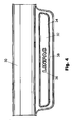
- FIG. 4 An example of a moulded product according to the invention is shown in Figure 4.
- the product is a scuff plate, intended to be fitted in the lower portion of a door opening of a car.
- the product includes an injection moulded body 30 having a decorative trim element 32 attached thereto.
- the face of the trim element 32 is recessed slightly below the peripheral region 34 of the trim element, so that it is protected from abrasion and scratching.
- a name, logo, texture or other kind of design may be applied to the foil: in this case, the registered trade mark LINPAC 36 is shown by way of example.
- a shallow groove 38 extends around the periphery of the decorative trim element 32, this groove 38 having been formed by the peripheral wall 18 in the mould.
- the groove 38 serves to create a visual boundary between the decorative trim element 32 and the moulded product 30, and creates the impression that the trim element consists of a solid metal plate.
Landscapes
- Engineering & Computer Science (AREA)
- Mechanical Engineering (AREA)
- Manufacturing & Machinery (AREA)
- Injection Moulding Of Plastics Or The Like (AREA)
Applications Claiming Priority (1)
| Application Number | Priority Date | Filing Date | Title |
|---|---|---|---|
| GB0414287A GB2415406A (en) | 2004-06-25 | 2004-06-25 | A decorative trim and method of manufacture |
Publications (2)
| Publication Number | Publication Date |
|---|---|
| EP1625925A2 true EP1625925A2 (de) | 2006-02-15 |
| EP1625925A3 EP1625925A3 (de) | 2006-03-01 |
Family
ID=32800204
Family Applications (1)
| Application Number | Title | Priority Date | Filing Date |
|---|---|---|---|
| EP05013521A Withdrawn EP1625925A3 (de) | 2004-06-25 | 2005-06-23 | Formteil und Verfahren zur Herstellung |
Country Status (2)
| Country | Link |
|---|---|
| EP (1) | EP1625925A3 (de) |
| GB (1) | GB2415406A (de) |
Cited By (1)
| Publication number | Priority date | Publication date | Assignee | Title |
|---|---|---|---|---|
| EP2777906A1 (de) * | 2013-03-15 | 2014-09-17 | RTI Sports Vertrieb von Sportartikeln GmbH | Spritzgussform für einen Fahrradgriff, Verfahren zur Herstellung eines Fahrradgriffs sowie Fahrradgriff |
Families Citing this family (7)
| Publication number | Priority date | Publication date | Assignee | Title |
|---|---|---|---|---|
| FR2905300B1 (fr) * | 2006-09-04 | 2008-10-17 | Mollertech Sas Soc Par Actions | Dispositif ameliore de fabrication d'une piece multicouche comprenant une couche d'aspect a surface granulee |
| FR2907728B1 (fr) * | 2006-10-25 | 2009-01-23 | Plastic Omnium Cie | Lot d'au moins deux elements decoratifs et/ou protecteurs d'un panneau de carrosserie |
| PL2147767T3 (pl) * | 2008-07-23 | 2013-09-30 | Pezzutti Group S P A | Sposób wytwarzania pokrywy z tworzywa sztucznego zawierającej etykietę z użyciem technologii wtapiania, forma do realizacji takiego sposobu i pokrywa uzyskana takim sposobem |
| ITTV20080099A1 (it) * | 2008-07-30 | 2010-01-31 | Plastal Spa | Procedimento di realizzazione d'un elemento battitacco o batticalcagno con placca di visualizzazione della marca per soglia battitacco di veicolo. |
| US8616869B2 (en) * | 2010-01-11 | 2013-12-31 | Vention Medical, Inc. | In-mold labeling apparatus and method |
| ITTO20130956A1 (it) * | 2013-11-25 | 2015-05-26 | Zanini Holding S P A | Procedimento ed apparecchiatura per la fabbricazione di un elemento decorativo, particolarmente utilizzabile come emblema per un autoveicolo, e relativo elemento decorativo. |
| US10839860B2 (en) * | 2019-04-15 | 2020-11-17 | Seagate Technology Llc | Methods and devices for reducing condensation in storage devices |
Family Cites Families (14)
| Publication number | Priority date | Publication date | Assignee | Title |
|---|---|---|---|---|
| US3270101A (en) * | 1963-04-01 | 1966-08-30 | Kaumagraph Co | Method of using static charge to decorate molded thermoplastic articles |
| CH442085A (de) * | 1966-07-27 | 1967-08-15 | Ornapress Ag | Verfahren zum Verzieren oder Beschriften von Kunststoffartikeln und Vorrichtung zur Durchführung des Verfahrens |
| GB1540679A (en) * | 1976-03-29 | 1979-02-14 | Nippon Petrochemicals Co Ltd | Thermoplastic resin pallet or pallet part with antiskid member and method for the manufacture thereof |
| JPS5791246A (en) * | 1980-11-29 | 1982-06-07 | Yoshida Kogyo Kk <Ykk> | Method and apparatus for molding cubic part automatically and decoratively |
| JPS61172714A (ja) * | 1985-01-28 | 1986-08-04 | Inoue Mtp Co Ltd | 装飾モ−ルとその製造方法 |
| JPH0671746B2 (ja) * | 1985-06-03 | 1994-09-14 | 釜屋化学工業株式会社 | インサ−ト成形製品の製造装置 |
| US5342666A (en) * | 1986-10-28 | 1994-08-30 | Rexham Industries Corp. | Injection molded plastic article with integral weatherable pigmented film surface |
| US4963403A (en) * | 1987-10-30 | 1990-10-16 | Color Custom, Inc. | Unitary composite molding strip |
| JP3039262B2 (ja) * | 1994-04-08 | 2000-05-08 | 豊田合成株式会社 | 樹脂製品の成形方法及び成形用金型装置 |
| WO1996009155A1 (en) * | 1994-09-23 | 1996-03-28 | The Geon Company | Method and device for injection molding |
| DE19729780C1 (de) * | 1997-07-11 | 1999-01-21 | Brocke Kg I B S | Verfahren zur Herstellung von hinterspritzten Kunststoffformteilen |
| JPH1134154A (ja) * | 1997-07-24 | 1999-02-09 | Nissan Motor Co Ltd | フィルム材のインサート成形装置及び方法 |
| JP2000351136A (ja) * | 1999-06-14 | 2000-12-19 | Pacific Ind Co Ltd | インサート成形金型 |
| FR2846904A1 (fr) * | 2002-11-08 | 2004-05-14 | Cera | Procede d'inclusion d'un revetement en medaillon sur une piece en matiere plastique |
-
2004
- 2004-06-25 GB GB0414287A patent/GB2415406A/en not_active Withdrawn
-
2005
- 2005-06-23 EP EP05013521A patent/EP1625925A3/de not_active Withdrawn
Cited By (1)
| Publication number | Priority date | Publication date | Assignee | Title |
|---|---|---|---|---|
| EP2777906A1 (de) * | 2013-03-15 | 2014-09-17 | RTI Sports Vertrieb von Sportartikeln GmbH | Spritzgussform für einen Fahrradgriff, Verfahren zur Herstellung eines Fahrradgriffs sowie Fahrradgriff |
Also Published As
| Publication number | Publication date |
|---|---|
| GB0414287D0 (en) | 2004-07-28 |
| EP1625925A3 (de) | 2006-03-01 |
| GB2415406A (en) | 2005-12-28 |
Similar Documents
| Publication | Publication Date | Title |
|---|---|---|
| US6132662A (en) | Foil-covered plastic part and method of making same | |
| EP2275307B1 (de) | Verfahren zur Herstellung eines Innenausstattungselements oder -hautelements für ein Kraftfahrzeug | |
| US7166249B2 (en) | Graphic image fusion | |
| US5604006A (en) | Label inmolding process and article of manufacture produced therefrom | |
| EP0845340B1 (de) | Formwerkzeug und Verfahren um eine Platte während des Giessformens festzuhalten | |
| US20030008134A1 (en) | Molding method and metal-covered component formed thereby | |
| US6168742B1 (en) | Method of insert molding auto and truck bumper, rocker panel and chin spoiler parts | |
| US6003895A (en) | Airbag pad with insert molded ornament | |
| US6180207B1 (en) | Foil-covered automatic interior plastic part having a decorative preform and method of making same | |
| KR20060105886A (ko) | 차량 부품 및 차량 부품 제조 방법 | |
| CN101500776B (zh) | 内饰用面板及注射成形方法 | |
| MX2007006999A (es) | Panel de guarnicion para vehiculo con multiples caracteristicas decorativas. | |
| AU2012258330B2 (en) | Article attachable to an exterior surface of a vehicle and method of forming the article | |
| WO2010106868A1 (ja) | 装飾モールおよび枠体付き車両用窓ガラス板 | |
| EP1625925A2 (de) | Formteil und Verfahren zur Herstellung | |
| WO2007000930A1 (ja) | 射出圧縮成形用金型 | |
| US20050017404A1 (en) | Method of molding a vehicle trim component | |
| US6548005B2 (en) | Multiple applique process for injection molding articles | |
| US6265044B1 (en) | Method of covering a profiled surface of a base member with a sheet by using bonding under vacuum, and a sheet suitable for use in the method | |
| US20050225006A1 (en) | Method for molding metal-covered component | |
| JP2001225350A (ja) | 射出成形同時絵付け方法 | |
| US20070026201A1 (en) | Molded articles and methods of producing them | |
| KR20180138305A (ko) | 일체형 엠블럼 제조장치 및 그 제조방법 | |
| CN211581788U (zh) | 徽章 | |
| KR102005884B1 (ko) | 로고 라벨 제조방법 및 이를 이용한 로고 라벨 |
Legal Events
| Date | Code | Title | Description |
|---|---|---|---|
| PUAI | Public reference made under article 153(3) epc to a published international application that has entered the european phase |
Free format text: ORIGINAL CODE: 0009012 |
|
| PUAL | Search report despatched |
Free format text: ORIGINAL CODE: 0009013 |
|
| AK | Designated contracting states |
Kind code of ref document: A2 Designated state(s): AT BE BG CH CY CZ DE DK EE ES FI FR GB GR HU IE IS IT LI LT LU MC NL PL PT RO SE SI SK TR |
|
| AX | Request for extension of the european patent |
Extension state: AL BA HR LV MK YU |
|
| AK | Designated contracting states |
Kind code of ref document: A3 Designated state(s): AT BE BG CH CY CZ DE DK EE ES FI FR GB GR HU IE IS IT LI LT LU MC NL PL PT RO SE SI SK TR |
|
| AX | Request for extension of the european patent |
Extension state: AL BA HR LV MK YU |
|
| 17P | Request for examination filed |
Effective date: 20060509 |
|
| AKX | Designation fees paid |
Designated state(s): AT BE BG CH CY CZ DE DK EE ES FI FR GB GR HU IE IS IT LI LT LU MC NL PL PT RO SE SI SK TR |
|
| 17Q | First examination report despatched |
Effective date: 20080124 |
|
| STAA | Information on the status of an ep patent application or granted ep patent |
Free format text: STATUS: THE APPLICATION IS DEEMED TO BE WITHDRAWN |
|
| 18D | Application deemed to be withdrawn |
Effective date: 20080805 |