EP1626167A2 - Moteur à combustion interne à injection directe - Google Patents
Moteur à combustion interne à injection directe Download PDFInfo
- Publication number
- EP1626167A2 EP1626167A2 EP05017401A EP05017401A EP1626167A2 EP 1626167 A2 EP1626167 A2 EP 1626167A2 EP 05017401 A EP05017401 A EP 05017401A EP 05017401 A EP05017401 A EP 05017401A EP 1626167 A2 EP1626167 A2 EP 1626167A2
- Authority
- EP
- European Patent Office
- Prior art keywords
- injection valve
- fuel injection
- spark plug
- fuel
- internal combustion
- Prior art date
- Legal status (The legal status is an assumption and is not a legal conclusion. Google has not performed a legal analysis and makes no representation as to the accuracy of the status listed.)
- Withdrawn
Links
Images

Classifications
-
- F—MECHANICAL ENGINEERING; LIGHTING; HEATING; WEAPONS; BLASTING
- F02—COMBUSTION ENGINES; HOT-GAS OR COMBUSTION-PRODUCT ENGINE PLANTS
- F02B—INTERNAL-COMBUSTION PISTON ENGINES; COMBUSTION ENGINES IN GENERAL
- F02B23/00—Other engines characterised by special shape or construction of combustion chambers to improve operation
- F02B23/08—Other engines characterised by special shape or construction of combustion chambers to improve operation with positive ignition
- F02B23/10—Other engines characterised by special shape or construction of combustion chambers to improve operation with positive ignition with separate admission of air and fuel into cylinder
- F02B23/101—Other engines characterised by special shape or construction of combustion chambers to improve operation with positive ignition with separate admission of air and fuel into cylinder the injector being placed on or close to the cylinder centre axis, e.g. with mixture formation using spray guided concepts
-
- Y—GENERAL TAGGING OF NEW TECHNOLOGICAL DEVELOPMENTS; GENERAL TAGGING OF CROSS-SECTIONAL TECHNOLOGIES SPANNING OVER SEVERAL SECTIONS OF THE IPC; TECHNICAL SUBJECTS COVERED BY FORMER USPC CROSS-REFERENCE ART COLLECTIONS [XRACs] AND DIGESTS
- Y02—TECHNOLOGIES OR APPLICATIONS FOR MITIGATION OR ADAPTATION AGAINST CLIMATE CHANGE
- Y02T—CLIMATE CHANGE MITIGATION TECHNOLOGIES RELATED TO TRANSPORTATION
- Y02T10/00—Road transport of goods or passengers
- Y02T10/10—Internal combustion engine [ICE] based vehicles
- Y02T10/12—Improving ICE efficiencies
Definitions
- the present invention relates to a direct injection internal combustion engine of a center injection type in which a fuel injection valve and a spark plug are disposed at a middle part of an upper part of a combustion chamber.
- Japanese Patent Application Publication No. H11(1999)-22592 discloses a direct injection internal combustion engine of a center injection type in which a fuel injection valve is disposed at a middle part of an upper part of a combustion chamber, and a spark plug is directed toward a central part of the combustion chamber.
- a fuel injection valve is disposed at a middle part of an upper part of a combustion chamber, and a spark plug is directed toward a central part of the combustion chamber.
- fuel is injected from the middle part of the upper part of the combustion chamber toward the central part of the combustion chamber to form a stratified air-fuel mixture in a wide-ranging area.
- Such direct gasoline-injection engine thereby can perform a stratified charge combustion in a wide region of operating range.
- the fuel injection valve is disposed at the middle part of the upper part of the combustion chamber, and thus is exposed to high temperature. This causes coking of the fuel to be deposited on inside and outside parts of the fuel injection valve, and thereby deteriorates capability of the fuel injection valve to inject the fuel. As a result, the above-mentioned internal combustion engine may not be able to perform an efficient stratified charge operation.
- cooling the fuel injection valve is an effective measure.
- the spark plug is disposed beside the fuel injection valve, and it is therefore difficult to provide a cooling channel between the fuel injection valve and the spark plug. If it is possible to provide a cooling channel between the fuel injection valve and the spark plug, such cooling channel would have a small width and be located far from an end portion of the fuel injection valve, and thus could not sufficiently cool the end portion of the fuel injection valve.
- the above-mentioned direct injection internal combustion engine of the center injection type cannot form a stratified air-fuel mixture in a wide-ranging area and perform a stratified charge combustion in a wide region of operating range.
- the fuel injection valve and the spark plug are inclined largely toward opposite directions which are parallel to a direction in which cylinders are arranged, it is possible to provide a large cooling channel in a thus-enlarged space therebetween.
- the fuel line and the high-tension cable or the ignition coil of adjacent cylinders may interfere with each other. As heretofore described, it is difficult for such direct injection internal combustion engine of earlier technology to sufficiently cool the end portion of the fuel injection valve.
- a direct injection internal combustion engine includes: a fuel injection valve including an injection nozzle formed with a nozzle hole facing toward a central part of a combustion chamber and arranged to inject fuel directly into the combustion chamber; a spark plug including an electrode facing toward the central part of the combustion chamber and arranged to spark-ignite the fuel injected from the fuel injection valve, the fuel injection valve and the spark plug of adjacent cylinders being inclined at different angles from each other in directions perpendicular to a cylinder arrangement direction in which the cylinders are arranged, and the fuel injection valve and the spark plug of at least one of the cylinders being inclined at different angles from each other in directions parallel to the cylinder arrangement direction; and a portion defining a cooling channel between the fuel injection valve and the spark plug of the at least one of the cylinders.
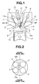
- FIG. 1 is a view showing a direct injection internal combustion engine according to an embodiment of the present invention, as viewed from front of the engine.
- FIG. 2 is a sectional view taken along a line II-II in FIG. 1, as viewed from downward of the engine.
- FIG. 3 is a view showing the direct injection internal combustion engine of FIG. 1, as viewed from side of the engine.
- FIG. 1 is a view showing a direct injection internal combustion engine according to an embodiment of the present invention, as viewed from front of the engine.
- FIG. 2 is a sectional view taken along a line II-II in FIG. 1, as viewed from downward of the engine.
- FIG. 3 is a view showing the direct injection internal combustion engine of FIG. 1, as viewed from side of the engine.
- the direct injection internal combustion engine of this embodiment includes a cylinder head 1 and a cylinder block 2 forming a plurality of cylinder portions or cylinders arranged in a cylinder arrangement direction. Each of the cylinder portions includes a piston 3, intake valves 5, intake ports 6, exhaust valves 7, and exhaust ports 8. Cylinder head 1, cylinder block 2 and piston 3 define a combustion chamber 4. Cylinder head 1 forms an upper surface of combustion chamber 4. Combustion chamber 4 communicates with intake ports 6 and exhaust ports 8 respectively via intake valves 5 and exhaust valves 7.
- the direct injection internal combustion engine of this embodiment or each of the cylinder portions also includes intake valve cams or intake cams 9, exhaust valve cams or exhaust cams 10, a fuel injection valve 11, a spark plug 12, a high-pressure fuel line 13, a high-tension cable 14, and a portion defining a cooling channel 16.
- intake valves 5 and exhaust valves 7 are actuated to open and close by intake valve cams 9 and exhaust valve cams 10, respectively.
- Fuel injection valve 11 and spark plug 12 are disposed at the upper surface or upper part of combustion chamber 4 with inclinations, as described hereinbelow.
- Fuel injection valve 11 includes an injection nozzle 11a formed with a nozzle hole.
- Spark plug 12 includes an electrode 12a.
- the nozzle hole or injection nozzle 11a, and electrode 12a face toward a central part of combustion chamber 4.
- High-pressure fuel line 13 is connected with an upper portion of fuel injection valve 11.
- High-tension cable 14 is connected with an upper portion of spark plug 12.
- Fuel is supplied via high-pressure fuel line 13 to fuel injection valve 11 to be injected directly from the nozzle hole of injection nozzle 11a into combustion chamber 4.
- Piston 3 includes a crown surface formed with a cavity 15 located at a central part of the crown surface.
- Cavity 15 is formed in a substantially cylindrical shape coaxial with an axis of fuel spray to be injected from fuel injection valve 11.
- the fuel injected from fuel injection valve 11 is to be headed toward a region above cavity 15 via (or directed back from) cavity 15 to form a stratified air-fuel mixture.
- the stratified air-fuel mixture is ignited by electrode 12a of spark plug 12 to conduct a stratified charge combustion.
- Fuel injection valve 11 and spark plug 12 are inclined at different angles (first and second angles; third and fourth angles) from each other in directions perpendicular to the cylinder arrangement direction. Fuel injection valve 11 and spark plug 12 may be inclined in any such perpendicular directions as long as the angles are different from each other: one of fuel injection valve 11 and spark plug 12 may be inclined at an angle of zero with respect to a vertical direction of the engine, i.e., disposed upright, and the other may be inclined at any angle; fuel injection valve 11 and spark plug 12 may be inclined toward opposite sides; or fuel injection valve 11 and spark plug 12 may be inclined toward a same side as long as the angles are different from each other.
- fuel injection valve 11 and spark plug 12 may preferably be inclined more largely toward opposite directions parallel to the cylinder arrangement direction, as shown in FIG. 3. However, depending on combustion performance and other layout limitations of the engine, one of fuel injection valve 11 and spark plug 12 may be disposed upright with respect to the engine, i.e., disposed at an angle of zero with respect to the vertical direction of the engine.
- an injection nozzle or nozzle hole of a fuel injection valve may preferably be disposed at a middle part of an upper part of a combustion chamber.
- an electrode of a spark plug may preferably be disposed at the middle part of the upper part of the combustion chamber. Therefore, in the four-valve engine of this embodiment, injection nozzle 11a and electrode 12a may preferably be disposed in a location surrounded by intake valves 5 and exhaust valves 7. In this case, injection nozzle 11a and electrode 12a may be arranged in line in a direction perpendicular to the cylinder arrangement direction, or alternatively, may be arranged in line in the cylinder arrangement direction.
- the fuel injection valve and the spark plug have to be inclined in directions perpendicular to the cylinder arrangement direction at small angles, because of interference with an intake camshaft and an exhaust camshaft located above. Consequently, it becomes difficult to provide a wide cooling channel in a space between the fuel injection valve and the spark plug of a same cylinder or cylinder portion.
- fuel injection valve 11 and spark plug 12 can be inclined in directions parallel to the cylinder arrangement direction at large angles, without interference with the intake camshaft and the exhaust camshaft. Consequently, wide cooling channel 16 can be provided in a space between fuel injection valve 11 and spark plug 12, as shown in FIG. 3.
- FIG. 4 is a detail view showing an arrangement of cooling channel 16.
- fuel injection valve 11 may be positioned upstream of the main flow of the cooling water, as shown in FIG. 4, and thus can be cooled effectively.
- spark plug 12 may be positioned downstream of the flow of the cooling water, as shown in FIG. 4. Positions of fuel injection valve 11 and spark plug 12 may be interchanged (i.e., spark plug to position 11 and fuel injection valve to position 12 in FIG. 4) due to other limitations.
- Cooling channel 16 may be arranged, not perpendicularly to the main flow of the cooling water, but obliquely with respect to the main flow of the cooling water, as shown in FIG. 4. This arrangement promotes inflow of the cooling water to cooling channel 16, and thus can enhance cooling effect for fuel injection valve 11.
- fuel injection valve 11 (or spark plug at position 11 as mentioned above) positioned upstream of the main flow of the cooling water may be inclined toward an exit of cooling channel 16, i.e., toward a side opposite from an entrance of cooling channel 16, as shown in FIG. 4. This promotes inflow of the cooling water to cooling channel 16, and thus can enhance cooling effect for fuel injection valve 11.
- the direct injection internal combustion engine of this embodiment or each of the cylinder portions may also include a block 17.
- Block 17 is located at the entrance of cooling channel 16, and projects against the main flow of the cooling water, as shown in FIG. 4. A part of the main flow collides with block 17, and the cooling water is forced to flow into cooling channel 16.
- the direct injection internal combustion engine of this embodiment can promote inflow of the cooling water to cooling channel 16, and thereby can enhance cooling effect for fuel injection valve 11.
- the direct injection internal combustion engine includes: means (11) for performing an injecting operation of injecting fuel from a first position directly into a combustion chamber; means (12) for performing an igniting operation of spark-igniting the fuel from a second position, the fuel being injected by the injecting operation, the first position and the second position being inclined at different angles from each other in directions perpendicular to a cylinder arrangement direction in which cylinders are arranged, and the first position and the second position being inclined at different angles from each.other in directions parallel to the cylinder arrangement direction; and means (16) for performing a cooling operation of cooling at least the first position from a third position defined between the first position and the second position.
Landscapes
- Engineering & Computer Science (AREA)
- Chemical & Material Sciences (AREA)
- Combustion & Propulsion (AREA)
- Mechanical Engineering (AREA)
- General Engineering & Computer Science (AREA)
- Combustion Methods Of Internal-Combustion Engines (AREA)
- Ignition Installations For Internal Combustion Engines (AREA)
- Fuel-Injection Apparatus (AREA)
- Cylinder Crankcases Of Internal Combustion Engines (AREA)
Applications Claiming Priority (1)
| Application Number | Priority Date | Filing Date | Title |
|---|---|---|---|
| JP2004234112A JP2006052666A (ja) | 2004-08-11 | 2004-08-11 | 筒内直接噴射式内燃機関 |
Publications (1)
| Publication Number | Publication Date |
|---|---|
| EP1626167A2 true EP1626167A2 (fr) | 2006-02-15 |
Family
ID=34979177
Family Applications (1)
| Application Number | Title | Priority Date | Filing Date |
|---|---|---|---|
| EP05017401A Withdrawn EP1626167A2 (fr) | 2004-08-11 | 2005-08-10 | Moteur à combustion interne à injection directe |
Country Status (3)
| Country | Link |
|---|---|
| US (1) | US7188589B2 (fr) |
| EP (1) | EP1626167A2 (fr) |
| JP (1) | JP2006052666A (fr) |
Cited By (1)
| Publication number | Priority date | Publication date | Assignee | Title |
|---|---|---|---|---|
| DE102009044158A1 (de) | 2008-10-02 | 2010-04-22 | Avl List Gmbh | Brennkraftmaschine mit einem Zylinderkopf |
Families Citing this family (8)
| Publication number | Priority date | Publication date | Assignee | Title |
|---|---|---|---|---|
| US20070004513A1 (en) * | 2002-08-06 | 2007-01-04 | Igt | Gaming machine with layered displays |
| US7444981B2 (en) | 2005-04-18 | 2008-11-04 | Nissan Motor Co., Ltd. | Internal-combustion engine and method of disposing ignition plug thereof |
| JP4742802B2 (ja) * | 2005-10-19 | 2011-08-10 | 日産自動車株式会社 | 筒内直噴エンジン |
| EP2058512A3 (fr) * | 2007-11-07 | 2015-05-20 | Mazda Motor Corporation | Structure supérieure d'un moteur |
| JP2009215951A (ja) * | 2008-03-10 | 2009-09-24 | Nissan Motor Co Ltd | 筒内直接噴射式内燃機関 |
| JP6262168B2 (ja) * | 2015-03-19 | 2018-01-17 | 本田技研工業株式会社 | 鞍乗型車両の筒内噴射式内燃機関 |
| JP6337877B2 (ja) * | 2015-12-10 | 2018-06-06 | マツダ株式会社 | 内燃機関の燃焼室構造 |
| JP2018105279A (ja) * | 2016-12-28 | 2018-07-05 | ヤマハ発動機株式会社 | 船外機 |
Citations (2)
| Publication number | Priority date | Publication date | Assignee | Title |
|---|---|---|---|---|
| JPH1122592A (ja) | 1997-06-30 | 1999-01-26 | Yamaha Motor Co Ltd | 筒内燃料噴射式エンジンの燃料レール取付構造 |
| JP2004234112A (ja) | 2003-01-28 | 2004-08-19 | Sekisui House Ltd | 建築費用積算システムおよびそのデータ構造 |
Family Cites Families (11)
| Publication number | Priority date | Publication date | Assignee | Title |
|---|---|---|---|---|
| EP0249699B1 (fr) * | 1986-06-19 | 1991-08-07 | Nippon Clean Engine Research Institute Co., Ltd. | Moteur à combustion interne à injection de carburant |
| DE19542494C1 (de) * | 1995-11-15 | 1997-01-30 | Daimler Benz Ag | Flüssigkeitsgekühlter Zylinderkopf für eine mehrzylindrige Brennkraftmaschine |
| DE19546945C2 (de) * | 1995-12-15 | 2003-04-30 | Daimler Chrysler Ag | Direkteinspritzende Brennkraftmaschine |
| DE19642653C5 (de) * | 1996-10-16 | 2008-02-21 | Daimler Ag | Verfahren zur Bildung eines zündfähigen Kraftstoff/Luft-Gemisches |
| JPH11182330A (ja) * | 1997-12-18 | 1999-07-06 | Nissan Motor Co Ltd | 直噴火花点火式内燃機関 |
| JP3585766B2 (ja) * | 1998-05-11 | 2004-11-04 | 本田技研工業株式会社 | ガソリン直噴エンジン |
| DE19911023C2 (de) * | 1999-03-12 | 2001-07-05 | Daimler Chrysler Ag | Direkteinspritzende Otto-Brennkraftmaschine |
| JP3730900B2 (ja) * | 2001-11-02 | 2006-01-05 | 本田技研工業株式会社 | 内燃機関 |
| DE50112871D1 (de) * | 2001-12-14 | 2007-09-27 | Ford Global Tech Llc | Brennkraftmaschine mit Direkteinspritzung |
| US6745745B2 (en) * | 2002-02-22 | 2004-06-08 | General Motors Corporation | Combustion chamber for reverse tumble spark ignition direct injection engine |
| JP4124009B2 (ja) * | 2003-04-10 | 2008-07-23 | いすゞ自動車株式会社 | 内燃機関のシリンダヘッド構造 |
-
2004
- 2004-08-11 JP JP2004234112A patent/JP2006052666A/ja active Pending
-
2005
- 2005-07-22 US US11/187,235 patent/US7188589B2/en not_active Expired - Fee Related
- 2005-08-10 EP EP05017401A patent/EP1626167A2/fr not_active Withdrawn
Patent Citations (2)
| Publication number | Priority date | Publication date | Assignee | Title |
|---|---|---|---|---|
| JPH1122592A (ja) | 1997-06-30 | 1999-01-26 | Yamaha Motor Co Ltd | 筒内燃料噴射式エンジンの燃料レール取付構造 |
| JP2004234112A (ja) | 2003-01-28 | 2004-08-19 | Sekisui House Ltd | 建築費用積算システムおよびそのデータ構造 |
Cited By (2)
| Publication number | Priority date | Publication date | Assignee | Title |
|---|---|---|---|---|
| DE102009044158A1 (de) | 2008-10-02 | 2010-04-22 | Avl List Gmbh | Brennkraftmaschine mit einem Zylinderkopf |
| DE102009044158B4 (de) | 2008-10-02 | 2019-06-13 | Avl List Gmbh | Zylinderkopf einer Brennkraftmaschine mit einem Kühlkanal zwischen der Zündeinrichtung und der Einspritzeinrichtung |
Also Published As
| Publication number | Publication date |
|---|---|
| US20060032478A1 (en) | 2006-02-16 |
| JP2006052666A (ja) | 2006-02-23 |
| US7188589B2 (en) | 2007-03-13 |
Similar Documents
| Publication | Publication Date | Title |
|---|---|---|
| EP0666409B1 (fr) | Moteur diesel à injection directe | |
| US6883491B2 (en) | Fuel injection system | |
| US5735240A (en) | Direct injected engine | |
| US6659070B2 (en) | Fuel injection system | |
| US7188589B2 (en) | Direct injection internal combustion engine | |
| JP2005201097A (ja) | 筒内噴射式内燃機関 | |
| US20080022967A1 (en) | Direct-Injection Spark-Ignition Internal Combustion Engine | |
| JP7673220B2 (ja) | 点火プラグとプレチャンバ点火プラグとを有する内燃機関 | |
| EP1777403B1 (fr) | Moteur à injection directe | |
| US6877477B2 (en) | Fuel injection system | |
| JP3777660B2 (ja) | 筒内直接噴射式火花点火内燃機関 | |
| US7500461B2 (en) | Rotary combustion engine, designed for diesel fuel | |
| JP4147981B2 (ja) | 直接筒内噴射式エンジンのインジェクタ配置構造 | |
| KR100306600B1 (ko) | 직접분사식가솔린엔진의피스톤 | |
| US8074621B2 (en) | In-cylinder injection type internal combustion engine | |
| US7571708B2 (en) | Spark ignited direct injection targeting for improved combustion | |
| JPWO2007066565A1 (ja) | エンジン | |
| GB2365071A (en) | Direct petrol injection IC engine with five valves and a spark plug and fuel injector arranged centrally to the combustion chamber, between the valves | |
| JP2002106353A (ja) | 火花点火式直噴エンジン | |
| JP2024089278A (ja) | 副燃焼室付内燃機関 | |
| JP3937650B2 (ja) | 筒内直接燃料噴射機関の燃焼室 | |
| JPH0658105B2 (ja) | エンジンの吸気装置 | |
| US20090064964A1 (en) | Spark ignited direct injection flow geometry for improved combustion | |
| WO2024201620A1 (fr) | Moteur à combustion interne du type à injection directe | |
| JP2007273421A (ja) | 点火プラグ |
Legal Events
| Date | Code | Title | Description |
|---|---|---|---|
| PUAI | Public reference made under article 153(3) epc to a published international application that has entered the european phase |
Free format text: ORIGINAL CODE: 0009012 |
|
| 17P | Request for examination filed |
Effective date: 20050810 |
|
| AK | Designated contracting states |
Kind code of ref document: A2 Designated state(s): AT BE BG CH CY CZ DE DK EE ES FI FR GB GR HU IE IS IT LI LT LU LV MC NL PL PT RO SE SI SK TR |
|
| AX | Request for extension of the european patent |
Extension state: AL BA HR MK YU |
|
| STAA | Information on the status of an ep patent application or granted ep patent |
Free format text: STATUS: THE APPLICATION HAS BEEN WITHDRAWN |
|
| 18W | Application withdrawn |
Effective date: 20100412 |