EP1626224A2 - Dispositif de distribution de lubrifiant - Google Patents
Dispositif de distribution de lubrifiant Download PDFInfo
- Publication number
- EP1626224A2 EP1626224A2 EP04019147A EP04019147A EP1626224A2 EP 1626224 A2 EP1626224 A2 EP 1626224A2 EP 04019147 A EP04019147 A EP 04019147A EP 04019147 A EP04019147 A EP 04019147A EP 1626224 A2 EP1626224 A2 EP 1626224A2
- Authority
- EP
- European Patent Office
- Prior art keywords
- lubricant
- piston
- agricultural
- pressure
- construction
- Prior art date
- Legal status (The legal status is an assumption and is not a legal conclusion. Google has not performed a legal analysis and makes no representation as to the accuracy of the status listed.)
- Withdrawn
Links
Images
Classifications
-
- F—MECHANICAL ENGINEERING; LIGHTING; HEATING; WEAPONS; BLASTING
- F16—ENGINEERING ELEMENTS AND UNITS; GENERAL MEASURES FOR PRODUCING AND MAINTAINING EFFECTIVE FUNCTIONING OF MACHINES OR INSTALLATIONS; THERMAL INSULATION IN GENERAL
- F16N—LUBRICATING
- F16N13/00—Lubricating-pumps
- F16N13/02—Lubricating-pumps with reciprocating piston
- F16N13/06—Actuation of lubricating-pumps
- F16N13/16—Actuation of lubricating-pumps with fluid drive
Definitions
- the invention relates to a device for supplying lubricant to a built-in a vehicle, a construction, agricultural or industrial machine lubricant distribution system that supplies a plurality of lubrication points with the interposition of one or more progressive distributor with lubricant, comprising a Dosier therenis, in which The lubricant receiving space is bounded by inner walls of the metering and a front side of a slidably mounted piston, wherein the lubricant receiving space further comprises a lubricant inlet for receiving a predetermined amount of lubricant and a lubricant outlet for delivering lubricant to the lubricant distribution system. Furthermore, the invention relates to a method for supplying lubricant to a built-in a vehicle, a construction, agricultural or industrial machine lubricant distribution system.
- Various devices and methods for metering lubricant in a lubricant distribution system comprising a metering container are known.
- specially designed dosing pumps are used which press lubricant into a lubricant distribution system at a desired dosage.
- a pre-metered amount of lubricant is manually injected into the lubricant distribution system.
- the manual injection of lubricant into a lubricant distribution system is extremely powerful, especially when one or more progressive distributors are interposed.
- the object of the present invention is to provide a device or to provide a method which allows to press a predetermined amount of lubricant in a simple manner in a lubricant distribution system.
- a central idea of the present invention consists in the fact that lubricant is no longer pressed manually into the lubricant distribution system installed in a vehicle, a construction, agricultural or industrial machine, but with the aid of pressurized fluid, which is used anyway for working equipment at the construction, agricultural or industrial machine is available.
- a hydraulic system is provided anyway for driving, for example, the blade, the excavator, etc.
- the pressure that can be provided in the hydraulic system of the excavator can now also be utilized to press lubricant into the lubricant distribution system.
- a Druckbeetzschungsraum on the side facing away from the lubricant receiving space of the piston is provided for this purpose, wherein the pressurizing space is acted upon via a pressure fluid connection with the provided by the vehicle, the construction, agricultural or industrial machine pressurized fluid, wherein pressurized fluid from both a hydraulic as well as from a pneumatic system according to the idea of the present invention can be used.
- the hydraulic pressure fluid without translation can be guided directly into the pressurization space and act there on the piston.
- pneumatic systems tend to be operated at lower pressures, so that when connected to a pneumatic pressure fluid may a translation to increase the pressure of the pressurized fluid would have to be provided.
- a metering device is provided on the metering, which allows adjustment or control of the displacement of the piston, such that per piston stroke an adjustable amount of lubricant is supplied to the lubricant distribution system.
- This makes it possible to respond to the respective lubricant requirement in a suitable manner, namely on the one hand by the fact that 10 the amount of lubricant supplied per piston stroke is precisely adjustable and on the other side in that can also be controlled or controlled, how often or in which Time intervals a piston stroke for the purpose of supplying lubricant is effected.
- the metering device may comprise a rod connected to the piston, which rod is guided through a wall of the metering container and protrudes beyond the metering container.
- the projection of the rod beyond the metering container also serves as a measure of the current volume of the lubricant receiving space and thus as a measure of the volume of the lubricant received in the lubricant receiving space.
- a scale is provided on the rod itself or in a housing in which the rod protruding above the dosing container is accommodated in order to be able to read the current value of the volume of the lubricant accommodating space or lubricant.
- the piston stroke during filling of the metering container can be limited, in that the filling process is controlled visually, for example 30 with the aid of a scale, or that other limiting means are used to limit the piston stroke to a desired value during the filling process.
- the storage of the rod in a guide in the frontal wall of the dosing is also regardless of whether the rod forms part of a metering device, makes sense, as this is a simple and straightforward structure for the device of the invention is provided.
- sealing means are provided in the region of the guide for sealing against the pressure of the pressure fluid.
- the piston 15 facing away from the end of the rod may be in a transparent housing, which is attached to the frontal wall of the dosing.
- the piston-remote end can move freely encapsulated in a housing.
- the rod is thus replaced by the transparent housing, which can also be regarded as an extension of the housing of Dosier meetingsnisses, a free movement space.
- the stroke of the piston can be controlled in both directions, and thus the amount of lubricant or lubricant already dispensed into the lubricant distribution system can be estimated.
- a particularly good control 25 can be achieved if markings in the manner of a scale are given to the transparent container and / or on the rod itself, which are expediently calibrated directly to the filling volume of the lubricant receiving space, for example in cm 3 .
- the filling of the metering container is not controlled or adjusted to a certain intermediate volume, but the metering container is filled to the maximum with lubricant, it is possible to control or adjust the opposite piston stroke when the lubricant is pressed into the lubricant distributor system. This can also be done only by visual inspection; It is particularly expedient, however, to provide limiting means on the moving rod at its end projecting beyond the metering container, which means after a corresponding piston stroke when the lubricant is pressed into the lubricant distributor system, it encounters a stop and thus limits the lubricant delivery.
- a thread on which a nut, if necessary together with a locking nut to a desired length position can be fixed.
- the stop could be formed by the outer surface of the frontal wall of the metering, so that the limiting nut comes after 10 a certain piston stroke on the front wall of the metering in contact and limits the lubricant delivery.
- the pressure fluid connection in a preferred development of the present invention comprises a throttle device.
- This throttle device can either firmly cause a predetermined throttling; However, it is particularly preferred if the throttle device is designed to be adjustable, so that the throttling effect can be increased or reduced.
- a throttle valve connected in parallel to the check valve which allows bypassing the throttle device, a return of the pressurized fluid and thus a reduction of the pressurization space when the vehicle of the construction, agricultural or industrial machine at the pressure fluid port opposite pressure below a certain return pressure P, has dropped.
- the lubricant receiving space can be refilled with lubricant as needed.
- a method for passing lubricant to a lubricant distribution system installed in a vehicle of a construction, agricultural or industrial machine, which supplies a plurality of lubricating points, possibly with the interposition of one or more progressive distributors, the method comprising the steps of: filling a lubricant receiving space of a dosing container with a predetermined amount of lubricant, pressing in the amount of lubricant absorbed in the dosing container the lubricant distribution system, wherein the pressing in under the action of pressurized fluid from a serving itself to drive working equipment pressure fluid system of a working device of a vehicle, a construction, agricultural or industrial machine takes place.
- This 5 method allows the injection of lubricant without the aid of complex lubricant pumps.
- the current volume i. the already recorded amount of lubricant checked, in particular, be read on a scale. This makes it easy to set or control a desired dosage.
- a pressurized space filled with pressurized fluid is emptied or reduced in particular by returning the pressurized fluid to the vehicle or to the construction, agricultural or industrial machine before or during refilling of the lubricant accommodating space.
- This return of the pressurized fluid can be carried out, for example, simultaneously with filling of the lubricant accommodating space by the pressure exerted by the lubricant on a piston.
- the expended pressure or force is so small that can be filled with a manually operable lubricant pump, the lubricant receiving space.
- a return of the pressurized fluid is advantageously carried out in a period in which in an admission in parallel connected working facilities with pressurized fluid does not occur and the pressure at a recirculation pressure P, has dropped.
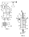
- FIG. 1 an embodiment of a device according to the invention for supplying lubricant to a built-in a vehicle, a construction, agricultural or industrial machine lubricant distribution system is shown in a schematic view.
- the device comprises a metering container 15 with a cylindrical circumferential inner wall 17, an end-side inner wall 18 and an end wall 29.
- a piston 20 is slidably mounted.
- the piston 20 divides the interior of the metering container 15 into a lubricant receiving space 16 and a pressurization chamber 23.
- the piston 20 has a front side 19 delimiting the lubricant receiving space 16 and a rear side 31 facing the pressurizing chamber 23.
- a rod 26 is connected, which is guided by a guide 35 in the frontal wall 29.
- the lubricant receiving space 16 can be filled with lubricant via a lubricant inlet 21 35.
- the lubricant inlet 21 further comprises an inlet-side check valve 37, which is a backflow of lubricant the lubricant receiving space 16 back into the lubricant inlet 21 prevented.
- a lubricant outlet 5 22 is also provided on the lubricant accommodating space 16, an outlet-side check valve 38 being connected at the same time in order to prevent a backflow of lubricant pressed into the lubricant outlet 22 into the lubricant accommodating space 16.
- a progressive distributor 14 may be connected, which promotes lubricant to a plurality of lubrication points 11, 12, 13.
- the latter For acting on the pressurizing chamber 23 with pressurized fluid 15, the latter has a pressurized fluid port 24, which in this case has concretely parallel to one another a throttling device 32 and a first nonreturn valve 33.
- the throttling device 32 is provided to restrict the flow of a pressurized fluid flowing into the pressurizing space 23.
- the check valve 33 allows a return of the pressurized fluid against the inflow device, bypassing the throttle device 32nd
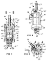
- Fig. 2 the dosing 15 is shown according to the invention in a side view.
- the frontal wall 18 and the opposite end wall 29 are each formed here as a cylindrical base plate 28, 30.
- the inner wall 17 forming circumferential, lateral container wall is clamped.
- the clamping takes place via four extending through the cylindrical base plate 30 bolts 39, 40, 41, 42 which engage with a threaded portion 43 respectively in a correspondingly formed internal thread in the cylindrical base plate 30.
- On the cylindrical base plates 28, 30 each circumferential sealing means 44, 45 are provided which cause a seal between container wall and base plates 28, 30.
- the piston 20 is guided with the already selected rod 26 in a bore 46 which defines a guide 35 for the rod 26 at the same time.
- the bore 46 has an extension to an outer surface 34 of the cylindrical base plate 28 through 5, are added to the sealing means 36 for sealing the pressurizing space 23 to the outside.
- a transparent housing 27 is screwed in as part of a metering device 25, such that the protruding over the bore 46 rod 26 is received in the transparent housing 27.
- the transparent housing 27 may further be provided with a scale graduation 48 in order to be able to read a current piston stroke from the position of the end of the rod 26 within the transparent housing 27 on the basis of the scale graduation 48.
- the already mentioned pressure fluid port 24 is further integrated, comprising the already mentioned throttle device 32 and arranged parallel thereto first check valve 20 33.
- the throttle device 32 specifically includes here a throttle screw which is adjustably arranged in a threaded channel 50, in such that the pressure fluid is guided by an adjustable thread length in the threaded channel 50, wherein it is supplied from a side channel 49 to the threaded channel 50.
- the opposite cylindrical base plate 28 are each lubricant inlet 21 with inlet-side check valve 37 and lubricant outlet 22 with outlet-side check valve 38 integrated.
- a fastening fitting 51 can be attached by means of second fastening screws 52, 53 to attach the dosing 15 to a driving, construction, agricultural or industrial machine.
Landscapes
- Engineering & Computer Science (AREA)
- General Engineering & Computer Science (AREA)
- Mechanical Engineering (AREA)
- Lubrication Of Internal Combustion Engines (AREA)
- Fluid-Pressure Circuits (AREA)
- Percussive Tools And Related Accessories (AREA)
Priority Applications (3)
| Application Number | Priority Date | Filing Date | Title |
|---|---|---|---|
| EP04019147A EP1626224A3 (fr) | 2004-08-12 | 2004-08-12 | Dispositif de distribution de lubrifiant |
| AT05017604T ATE545822T1 (de) | 2004-08-12 | 2005-08-12 | Einrichtung zur zuführung von schmierstoff |
| EP20050017604 EP1626225B1 (fr) | 2004-08-12 | 2005-08-12 | Dispositif de distribution de lubrifiant |
Applications Claiming Priority (1)
| Application Number | Priority Date | Filing Date | Title |
|---|---|---|---|
| EP04019147A EP1626224A3 (fr) | 2004-08-12 | 2004-08-12 | Dispositif de distribution de lubrifiant |
Publications (2)
| Publication Number | Publication Date |
|---|---|
| EP1626224A2 true EP1626224A2 (fr) | 2006-02-15 |
| EP1626224A3 EP1626224A3 (fr) | 2008-04-30 |
Family
ID=34926143
Family Applications (1)
| Application Number | Title | Priority Date | Filing Date |
|---|---|---|---|
| EP04019147A Withdrawn EP1626224A3 (fr) | 2004-08-12 | 2004-08-12 | Dispositif de distribution de lubrifiant |
Country Status (2)
| Country | Link |
|---|---|
| EP (1) | EP1626224A3 (fr) |
| AT (1) | ATE545822T1 (fr) |
Cited By (2)
| Publication number | Priority date | Publication date | Assignee | Title |
|---|---|---|---|---|
| CN113154240A (zh) * | 2020-01-07 | 2021-07-23 | 无锡科里斯特科技有限公司 | 一种可调小流量气动油泵 |
| CN119755505A (zh) * | 2025-03-05 | 2025-04-04 | 江苏嘉通能源有限公司 | 润滑剂安全加注装置及其控制系统、控制方法 |
Family Cites Families (6)
| Publication number | Priority date | Publication date | Assignee | Title |
|---|---|---|---|---|
| GB1454184A (en) * | 1974-09-18 | 1976-10-27 | Assa Ab | Lubrication system |
| EP0244182A3 (fr) * | 1986-05-01 | 1989-01-18 | Castrol Limited | Dispositifs de graissage |
| US5029672A (en) * | 1989-10-13 | 1991-07-09 | Am International | Lubricating system for printing, duplicating and like machines |
| SE466091B (sv) * | 1990-11-15 | 1991-12-16 | Bohult Maskin Ab | Saett och anordning foer smoerjning av en saagkedja |
| US5285871A (en) * | 1992-08-17 | 1994-02-15 | Mechanical Tool & Engineering Co. | System for distributing viscous lubricant |
| GB2358441A (en) * | 2000-01-18 | 2001-07-25 | Jo Bee Liu | Axle bearing lubricating device |
-
2004
- 2004-08-12 EP EP04019147A patent/EP1626224A3/fr not_active Withdrawn
-
2005
- 2005-08-12 AT AT05017604T patent/ATE545822T1/de active
Cited By (2)
| Publication number | Priority date | Publication date | Assignee | Title |
|---|---|---|---|---|
| CN113154240A (zh) * | 2020-01-07 | 2021-07-23 | 无锡科里斯特科技有限公司 | 一种可调小流量气动油泵 |
| CN119755505A (zh) * | 2025-03-05 | 2025-04-04 | 江苏嘉通能源有限公司 | 润滑剂安全加注装置及其控制系统、控制方法 |
Also Published As
| Publication number | Publication date |
|---|---|
| ATE545822T1 (de) | 2012-03-15 |
| EP1626224A3 (fr) | 2008-04-30 |
Similar Documents
| Publication | Publication Date | Title |
|---|---|---|
| DE102004003683B4 (de) | Flüssigmaterial-Versorgungssystem | |
| EP0003563B1 (fr) | Dispositif pour doser au moins deux composantes fluidisables entrant en réaction dans une chambre de mélange | |
| EP2585255B1 (fr) | Dispositif de serrage de vis | |
| DE69625096T2 (de) | Vorrichtung zur Abgabe von mindestens zwei Komponenten | |
| EP0946830A1 (fr) | Systeme d'injection de carburant pour moteur a combustion interne | |
| DE19948602A1 (de) | Schüttgutpumpenvorrichtung | |
| DE2603563C2 (de) | Steuereinrichtung für ein aus mindestens zwei Pumpen bestehendes Pumpen-Aggregat | |
| EP2613058A2 (fr) | Hydraulic system | |
| DE102004010774B4 (de) | Materialzuführsystem | |
| DE69606972T2 (de) | Vorrichtung zur Abgabe von wenigstens zwei Komponenten | |
| DE3005231A1 (de) | Mischkopf mit einem staubkoerper | |
| DE2656056A1 (de) | Kolbenpumpe | |
| EP1626225B1 (fr) | Dispositif de distribution de lubrifiant | |
| EP2229537B1 (fr) | Dispositif d'entraînement hydraulique à deux chambres de pression, et procédé permettant de faire fonctionner un dispositif d'entraînement hydraulique à deux chambres de pression | |
| DE2510647A1 (de) | Druckbegrenzungsventil | |
| DE2544794A1 (de) | Hydraulische presse mit konstantspeicher | |
| EP1626224A2 (fr) | Dispositif de distribution de lubrifiant | |
| DE2803706A1 (de) | Reduzierventil fuer hydraulisch angetriebene maschinen und maschinelle einrichtungen | |
| DE102004038801B4 (de) | Verfahren und Vorrichtung zur Erkennung von Gaseinschlüssen in einem zähflüssigen Medium | |
| DE2754430A1 (de) | Steuereinrichtung fuer mindestens zwei verstellbare pumpen | |
| AT398942B (de) | Dosiervorrichtung zur festlegung des entlade- und ladevolumens der hydraulikflüssigkeit eines dosierbaren energiespeichers einer hydraulikanlage, insbesondere einer hydraulischen schlagpresse | |
| DE3332189C1 (de) | Landwirtschaftliches Gerät zum dosierten Ausbringen von Flüssigkeiten | |
| DE4327602C1 (de) | Hochdruckpumpenaggregat | |
| AT403833B (de) | Vorrichtung zum fördern von fliessfähigen substanzen | |
| DE2641250A1 (de) | Druckfluid-impulsfrequenzumwandler |
Legal Events
| Date | Code | Title | Description |
|---|---|---|---|
| PUAI | Public reference made under article 153(3) epc to a published international application that has entered the european phase |
Free format text: ORIGINAL CODE: 0009012 |
|
| AK | Designated contracting states |
Kind code of ref document: A2 Designated state(s): AT BE BG CH CY CZ DE DK EE ES FI FR GB GR HU IE IT LI LU MC NL PL PT RO SE SI SK TR |
|
| AX | Request for extension of the european patent |
Extension state: AL HR LT LV MK |
|
| PUAL | Search report despatched |
Free format text: ORIGINAL CODE: 0009013 |
|
| AK | Designated contracting states |
Kind code of ref document: A3 Designated state(s): AT BE BG CH CY CZ DE DK EE ES FI FR GB GR HU IE IT LI LU MC NL PL PT RO SE SI SK TR |
|
| AX | Request for extension of the european patent |
Extension state: AL HR LT LV MK |
|
| 17P | Request for examination filed |
Effective date: 20080811 |
|
| AKX | Designation fees paid |
Designated state(s): DE ES FR IT |
|
| 17Q | First examination report despatched |
Effective date: 20101227 |
|
| STAA | Information on the status of an ep patent application or granted ep patent |
Free format text: STATUS: THE APPLICATION HAS BEEN WITHDRAWN |
|
| 18W | Application withdrawn |
Effective date: 20120220 |