EP1626432A1 - Appareillage de pulvérisation magnétron, cathode cylindrique et méthod de depot des couches minces de matériaux différents sur un substrat - Google Patents
Appareillage de pulvérisation magnétron, cathode cylindrique et méthod de depot des couches minces de matériaux différents sur un substrat Download PDFInfo
- Publication number
- EP1626432A1 EP1626432A1 EP04018925A EP04018925A EP1626432A1 EP 1626432 A1 EP1626432 A1 EP 1626432A1 EP 04018925 A EP04018925 A EP 04018925A EP 04018925 A EP04018925 A EP 04018925A EP 1626432 A1 EP1626432 A1 EP 1626432A1
- Authority
- EP
- European Patent Office
- Prior art keywords
- segments
- cathode
- cylinder
- cylinder cathode
- magnetron sputtering
- Prior art date
- Legal status (The legal status is an assumption and is not a legal conclusion. Google has not performed a legal analysis and makes no representation as to the accuracy of the status listed.)
- Withdrawn
Links
- 239000000758 substrate Substances 0.000 title claims abstract description 39
- 239000000463 material Substances 0.000 title claims abstract description 38
- 238000001755 magnetron sputter deposition Methods 0.000 title claims abstract description 31
- 238000000034 method Methods 0.000 title claims abstract description 22
- 239000010409 thin film Substances 0.000 title 1
- 239000013077 target material Substances 0.000 claims abstract description 22
- 230000010355 oscillation Effects 0.000 claims abstract description 4
- 239000011248 coating agent Substances 0.000 claims description 7
- 238000000576 coating method Methods 0.000 claims description 7
- 238000004544 sputter deposition Methods 0.000 claims description 6
- 238000001771 vacuum deposition Methods 0.000 claims description 6
- 238000000151 deposition Methods 0.000 description 5
- 230000008021 deposition Effects 0.000 description 5
- 238000004519 manufacturing process Methods 0.000 description 4
- 238000007750 plasma spraying Methods 0.000 description 4
- 238000012423 maintenance Methods 0.000 description 3
- PXHVJJICTQNCMI-UHFFFAOYSA-N Nickel Chemical compound [Ni] PXHVJJICTQNCMI-UHFFFAOYSA-N 0.000 description 2
- 230000015572 biosynthetic process Effects 0.000 description 2
- 238000011109 contamination Methods 0.000 description 2
- 229910052751 metal Inorganic materials 0.000 description 2
- 239000002184 metal Substances 0.000 description 2
- 150000002739 metals Chemical class 0.000 description 2
- 239000002245 particle Substances 0.000 description 2
- BASFCYQUMIYNBI-UHFFFAOYSA-N platinum Chemical compound [Pt] BASFCYQUMIYNBI-UHFFFAOYSA-N 0.000 description 2
- 238000005476 soldering Methods 0.000 description 2
- 238000003466 welding Methods 0.000 description 2
- RSWGJHLUYNHPMX-RMGPQRKISA-N (1r,4ar,4br)-1,4a-dimethyl-7-propan-2-yl-2,3,4,4b,5,6,10,10a-octahydrophenanthrene-1-carboxylic acid Chemical compound C([C@@H]12)CC(C(C)C)=CC1=CCC1[C@]2(C)CCC[C@@]1(C)C(O)=O RSWGJHLUYNHPMX-RMGPQRKISA-N 0.000 description 1
- VYZAMTAEIAYCRO-UHFFFAOYSA-N Chromium Chemical compound [Cr] VYZAMTAEIAYCRO-UHFFFAOYSA-N 0.000 description 1
- RYGMFSIKBFXOCR-UHFFFAOYSA-N Copper Chemical compound [Cu] RYGMFSIKBFXOCR-UHFFFAOYSA-N 0.000 description 1
- ZOKXTWBITQBERF-UHFFFAOYSA-N Molybdenum Chemical compound [Mo] ZOKXTWBITQBERF-UHFFFAOYSA-N 0.000 description 1
- 229910052779 Neodymium Inorganic materials 0.000 description 1
- BQCADISMDOOEFD-UHFFFAOYSA-N Silver Chemical compound [Ag] BQCADISMDOOEFD-UHFFFAOYSA-N 0.000 description 1
- ATJFFYVFTNAWJD-UHFFFAOYSA-N Tin Chemical compound [Sn] ATJFFYVFTNAWJD-UHFFFAOYSA-N 0.000 description 1
- RTAQQCXQSZGOHL-UHFFFAOYSA-N Titanium Chemical compound [Ti] RTAQQCXQSZGOHL-UHFFFAOYSA-N 0.000 description 1
- HCHKCACWOHOZIP-UHFFFAOYSA-N Zinc Chemical compound [Zn] HCHKCACWOHOZIP-UHFFFAOYSA-N 0.000 description 1
- 238000004026 adhesive bonding Methods 0.000 description 1
- 229910052782 aluminium Inorganic materials 0.000 description 1
- XAGFODPZIPBFFR-UHFFFAOYSA-N aluminium Chemical compound [Al] XAGFODPZIPBFFR-UHFFFAOYSA-N 0.000 description 1
- 239000006117 anti-reflective coating Substances 0.000 description 1
- 238000000889 atomisation Methods 0.000 description 1
- 238000005452 bending Methods 0.000 description 1
- 239000013590 bulk material Substances 0.000 description 1
- 239000000919 ceramic Substances 0.000 description 1
- 229910052804 chromium Inorganic materials 0.000 description 1
- 239000011651 chromium Substances 0.000 description 1
- 150000001875 compounds Chemical class 0.000 description 1
- 229910052802 copper Inorganic materials 0.000 description 1
- 239000010949 copper Substances 0.000 description 1
- 238000005520 cutting process Methods 0.000 description 1
- 238000011161 development Methods 0.000 description 1
- 230000018109 developmental process Effects 0.000 description 1
- 230000000694 effects Effects 0.000 description 1
- 230000003628 erosive effect Effects 0.000 description 1
- PCHJSUWPFVWCPO-UHFFFAOYSA-N gold Chemical compound [Au] PCHJSUWPFVWCPO-UHFFFAOYSA-N 0.000 description 1
- 229910052737 gold Inorganic materials 0.000 description 1
- 239000010931 gold Substances 0.000 description 1
- 238000001513 hot isostatic pressing Methods 0.000 description 1
- 229910044991 metal oxide Inorganic materials 0.000 description 1
- 150000004706 metal oxides Chemical class 0.000 description 1
- 238000003801 milling Methods 0.000 description 1
- 229910052750 molybdenum Inorganic materials 0.000 description 1
- 239000011733 molybdenum Substances 0.000 description 1
- QEFYFXOXNSNQGX-UHFFFAOYSA-N neodymium atom Chemical compound [Nd] QEFYFXOXNSNQGX-UHFFFAOYSA-N 0.000 description 1
- 229910052759 nickel Inorganic materials 0.000 description 1
- 230000005693 optoelectronics Effects 0.000 description 1
- 229910052697 platinum Inorganic materials 0.000 description 1
- 238000005096 rolling process Methods 0.000 description 1
- 229910052709 silver Inorganic materials 0.000 description 1
- 239000004332 silver Substances 0.000 description 1
- 238000003860 storage Methods 0.000 description 1
- 229910052718 tin Inorganic materials 0.000 description 1
- 239000011135 tin Substances 0.000 description 1
- 239000010936 titanium Substances 0.000 description 1
- 229910052719 titanium Inorganic materials 0.000 description 1
- WFKWXMTUELFFGS-UHFFFAOYSA-N tungsten Chemical compound [W] WFKWXMTUELFFGS-UHFFFAOYSA-N 0.000 description 1
- 229910052721 tungsten Inorganic materials 0.000 description 1
- 239000010937 tungsten Substances 0.000 description 1
- 229910052725 zinc Inorganic materials 0.000 description 1
- 239000011701 zinc Substances 0.000 description 1
Images
Classifications
-
- H—ELECTRICITY
- H01—ELECTRIC ELEMENTS
- H01J—ELECTRIC DISCHARGE TUBES OR DISCHARGE LAMPS
- H01J37/00—Discharge tubes with provision for introducing objects or material to be exposed to the discharge, e.g. for the purpose of examination or processing thereof
- H01J37/32—Gas-filled discharge tubes
- H01J37/34—Gas-filled discharge tubes operating with cathodic sputtering
- H01J37/3411—Constructional aspects of the reactor
- H01J37/3414—Targets
- H01J37/3426—Material
- H01J37/3429—Plural materials
-
- C—CHEMISTRY; METALLURGY
- C23—COATING METALLIC MATERIAL; COATING MATERIAL WITH METALLIC MATERIAL; CHEMICAL SURFACE TREATMENT; DIFFUSION TREATMENT OF METALLIC MATERIAL; COATING BY VACUUM EVAPORATION, BY SPUTTERING, BY ION IMPLANTATION OR BY CHEMICAL VAPOUR DEPOSITION, IN GENERAL; INHIBITING CORROSION OF METALLIC MATERIAL OR INCRUSTATION IN GENERAL
- C23C—COATING METALLIC MATERIAL; COATING MATERIAL WITH METALLIC MATERIAL; SURFACE TREATMENT OF METALLIC MATERIAL BY DIFFUSION INTO THE SURFACE, BY CHEMICAL CONVERSION OR SUBSTITUTION; COATING BY VACUUM EVAPORATION, BY SPUTTERING, BY ION IMPLANTATION OR BY CHEMICAL VAPOUR DEPOSITION, IN GENERAL
- C23C14/00—Coating by vacuum evaporation, by sputtering or by ion implantation of the coating forming material
- C23C14/22—Coating by vacuum evaporation, by sputtering or by ion implantation of the coating forming material characterised by the process of coating
- C23C14/34—Sputtering
- C23C14/3407—Cathode assembly for sputtering apparatus, e.g. Target
-
- C—CHEMISTRY; METALLURGY
- C23—COATING METALLIC MATERIAL; COATING MATERIAL WITH METALLIC MATERIAL; CHEMICAL SURFACE TREATMENT; DIFFUSION TREATMENT OF METALLIC MATERIAL; COATING BY VACUUM EVAPORATION, BY SPUTTERING, BY ION IMPLANTATION OR BY CHEMICAL VAPOUR DEPOSITION, IN GENERAL; INHIBITING CORROSION OF METALLIC MATERIAL OR INCRUSTATION IN GENERAL
- C23C—COATING METALLIC MATERIAL; COATING MATERIAL WITH METALLIC MATERIAL; SURFACE TREATMENT OF METALLIC MATERIAL BY DIFFUSION INTO THE SURFACE, BY CHEMICAL CONVERSION OR SUBSTITUTION; COATING BY VACUUM EVAPORATION, BY SPUTTERING, BY ION IMPLANTATION OR BY CHEMICAL VAPOUR DEPOSITION, IN GENERAL
- C23C14/00—Coating by vacuum evaporation, by sputtering or by ion implantation of the coating forming material
- C23C14/22—Coating by vacuum evaporation, by sputtering or by ion implantation of the coating forming material characterised by the process of coating
- C23C14/34—Sputtering
- C23C14/35—Sputtering by application of a magnetic field, e.g. magnetron sputtering
-
- H—ELECTRICITY
- H01—ELECTRIC ELEMENTS
- H01J—ELECTRIC DISCHARGE TUBES OR DISCHARGE LAMPS
- H01J37/00—Discharge tubes with provision for introducing objects or material to be exposed to the discharge, e.g. for the purpose of examination or processing thereof
- H01J37/32—Gas-filled discharge tubes
- H01J37/34—Gas-filled discharge tubes operating with cathodic sputtering
- H01J37/3402—Gas-filled discharge tubes operating with cathodic sputtering using supplementary magnetic fields
- H01J37/3405—Magnetron sputtering
-
- H—ELECTRICITY
- H01—ELECTRIC ELEMENTS
- H01J—ELECTRIC DISCHARGE TUBES OR DISCHARGE LAMPS
- H01J37/00—Discharge tubes with provision for introducing objects or material to be exposed to the discharge, e.g. for the purpose of examination or processing thereof
- H01J37/32—Gas-filled discharge tubes
- H01J37/34—Gas-filled discharge tubes operating with cathodic sputtering
- H01J37/3411—Constructional aspects of the reactor
- H01J37/345—Magnet arrangements in particular for cathodic sputtering apparatus
- H01J37/3455—Movable magnets
Definitions
- the invention relates to a magnetron sputtering device, a cylindrical cathode and a method for applying thin layers of different materials on a substrate according to the preambles of claim 1, claim 4 and claim 10.
- Magnetron sputtering devices i. Targets with magnet structures that make it possible to sputter in the direction of a substrate have long been known in the application in vacuum coating systems for coating various substrates and suitable for coating with a variety of layer materials.
- Such vacuum coating systems comprise working chambers in which the coating takes place. These vacuum chambers have a base pressure in a required vacuum range which, in accordance with the process parameters, prevents in particular contamination during the layer deposition.
- the vacuum chambers have a working pressure that can be significantly above the base pressure and is caused by the process gas.
- Tube cathodes are used which are constructed completely from a target bulk material, as described for example in DD 217 964.
- support tubes which are provided with a circumferentially applied layer of target material, as described in US Pat. No. 4,356,073. The uniform rotation of the tube cathode achieves a uniform erosion of the target material on the tube cathode surface, since locally concentrated atomization and thus furrow formation is prevented.
- the substrate can be transported successively into different vacuum chambers in which one or more sputtering cathodes are located. All cathodes of a chamber have the same target material.
- the substrate is transported from one chamber to another chamber, and each coated with a layer of a target material. After the selected layer thickness is achieved, the substrate is transported into another chamber and provided with a further layer.
- a disadvantage of this method is that a very large vacuum system is necessary by the transport of the substrate through a plurality of vacuum chambers. This makes the investment in purchase and maintenance very expensive. In addition, the transport can generate particles that can contaminate the substrate.
- planar targets of different material may be arranged in a single vacuum chamber, e.g. described in US 2003/0085122.
- the individual targets, each having its own magnetic systems, are successively rotated in front of the substrate and a film of desired thickness is applied to the substrate.
- a vacuum chamber there may be several substrate holders.
- a disadvantage of the planar targets is that only a small target utilization is possible with them and that they have a large redeposition range. The large redeposition zones create process-related difficulties and lead to a poorer quality of coating on the substrate.
- the target utilization should be as large as possible and the redeposition on the target should be as small as possible.
- the magnetron sputtering device which in particular comprises at least one vacuum chamber and is provided in particular for the continuous application of several layers of different materials on a substrate, is provided with a cylinder cathode rotatably mounted about the axial longitudinal axis and a magnet system.
- the magnet system is arranged in the interior of the cylinder cathode.
- the cylinder cathode comprises at least two segments with different target materials, and the magnetron sputtering device has means for rotating the cylinder cathode, by means of which the cylinder cathode (1, 1 ') is rotated around the longitudinal axis for application of a layer until the segment (FIG.
- the magnetron sputtering means comprises means for oscillating the cylinder cathode about the longitudinal axis over the internal magnet system during the deposition of the layers on the substrate, wherein the oscillation is alternately rotated clockwise and counterclockwise.
- the Magnetronsputterer boots has means for limiting the oscillation, so that only material of a variety is sputtered.
- the magnetron sputtering device comprises a plurality of cylindrical cathodes.
- a magnetron sputtering device With such a magnetron sputtering device, multiple layers can be applied in succession on a substrate, whereby even very large-area substrates can be coated.
- the magnetron sputtering device can be made very compact, since in contrast to a Magnetronsputter overlooked with Mehrfachplanartargets only a magnetic system is required.
- the vacuum coating systems can be significantly reduced in size by the use of the magnetron sputtering device according to the invention. As a result, the cost of purchase and maintenance, which includes not only the pure operating costs but also the cost of the required floor space can be reduced.
- the cylinder cathode according to the invention which can be used in particular in the magnetron sputtering apparatus described above, comprises at least two segments with different target materials. It is advantageous if the individual segments are designed as cylinder segments. However, it may also be necessary to make the segments planar on their outside when the application of the segments e.g. by plasma spraying is not possible. For example, ceramic compounds in the plasma spraying process can not always be applied to a tube target with a required material density and homogeneity.
- the cylinder cathode may also include individual segments which are spaced apart. However, this distance is to be so dimensioned that just no discharge can occur in the gap between the segments.
- the individual segments can be arranged on a support tube.
- all metals, metal oxides and materials from which no self-supporting segments can be produced because of manufacturing problems can be applied to support tubes.
- Manufacturing processes for this are, for example, hot isostatic pressing, plasma spraying and bonding or gluing.
- all metals from which one can produce self-supporting segments for example by cutting, drawing, milling, bending or rolling, wherein the segments can be connected together, for example by soldering or welding, but also by mechanical solutions such as dovetail guides to a target, used for the production of full targets. This applies in particular to tin, zinc, nickel, copper, aluminum, silver, gold, platinum, molybdenum, titanium and neodymium.
- Typical dimensions for the cylindrical cathode targets are lengths of 500 to 4500 mm, diameters of 100 to 300 mm and wall thicknesses of 1 to 50 mm.
- the circular arcs of the individual cylinder segments have such a size that the volumes of the segments are adapted to the sputtering conditions of the individual layers to be applied so that the service life of the individual segments is equalized. In this way, the target life can be extended.
- the inventive method for applying thin layers of different materials on a substrate by magnetron sputtering in a vacuum coating system now comprises the following, successively executed steps.
- a cylinder cathode rotatably mounted about the axial longitudinal direction and comprising at least two segments of different materials is oscillated during the application of a layer on the substrate about the longitudinal axis via an internal magnet system in which the rotation takes place alternately clockwise and anticlockwise so far that only material of one kind is sputtered.
- the cylinder cathode is rotated about the longitudinal axis until the segment with the desired material is above the magnet system, whereby the plasma discharge can be erased if necessary and regenerated after reaching the next target section.
- the method can be designed if the life of the segments is adjusted by the fact that the volumes of the individual material segments are designed according to the sputtering conditions in the application of the individual layers.
- a plurality of cylinder cathodes arranged in the magnetron sputtering device are advantageously used for layer deposition. If many different layers are to be applied to one substrate, it may be advisable to apply individual layer sections comprising first materials in a first vacuum chamber and to apply layer sections comprising further materials in one or more further vacuum chambers.
- the above-described invention has the advantage that the movement of the target during the sputtering process results in a higher Target utilization and a much lower redeposition is achieved.
- the advantage over the system of applying one layer per chamber is that the size of the system is significantly reduced.
- a plurality of cylindrical cathodes arranged in the magnetron sputtering device are used for layer deposition.
- the layer deposition can be accelerated.
- contamination of the various targets can be avoided.
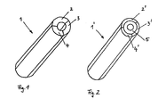
- the cylinder cathode 1 according to the invention according to FIG. 1 is designed as a cylinder tube.
- the cylinder cathode 1 consists entirely of target material and in the illustrated case comprises three target materials. Each target material is located in a separate cylinder segment 2, 3 and 4.
- the three segments 2, 3 and 4 each have a circular arc of 120 ° and a common length corresponding to the length of the cylinder cathode 1, 1 '.
- the segments are directly connected to each other by welding, soldering or mechanical solutions such as a dovetail guide.
- the cylinder cathode 1 ' is formed in a simple manner by applying different target material on a support tube 5, as shown in Fig. 2.
- the individual cylinder segments 2 ', 3' and 4 ' may e.g. be applied by plasma spraying on the support tube 5. They adjoin one another directly and have the same length and the same circular arcs of 120 °.
- the cylinder cathodes 1 and 1 ' are provided with suitable means (not shown) which allow the storage of the cylindrical cathodes 1 and 1' via a known magnet system arranged in their interior and an axially symmetric rotational movement about their longitudinal axis.
- the cylinder cathode 1 is rotated so that the cylinder segment 1 with the first material is above the magnet system, where appropriate, the plasma discharge deleted and can be generated again after reaching the next target section.
- This material can now be applied to a substrate by means of the known magnetron effect.
- the cylinder cathode 1 is oscillating during the application of the first material, that is, rotated alternately clockwise and anticlockwise until only material from the first segment 1 is sputtered.
- the cylinder cathode is rotated to the second segment 2 and in turn applied by alternately rotating clockwise and counterclockwise the second material on the substrate. This process can now be continued with the third segment 3.
- a plurality of cylindrical cathodes 1, 1 ' can be used in a magnetron sputtering device.
- a plurality of vacuum chambers with magnetron sputtering devices which are each provided with different cylinder cathodes with different combinations of target materials, can be arranged one after the other.
Landscapes
- Chemical & Material Sciences (AREA)
- Engineering & Computer Science (AREA)
- Physics & Mathematics (AREA)
- Plasma & Fusion (AREA)
- Analytical Chemistry (AREA)
- Chemical Kinetics & Catalysis (AREA)
- Materials Engineering (AREA)
- Mechanical Engineering (AREA)
- Metallurgy (AREA)
- Organic Chemistry (AREA)
- Physical Vapour Deposition (AREA)
Priority Applications (1)
| Application Number | Priority Date | Filing Date | Title |
|---|---|---|---|
| EP04018925A EP1626432A1 (fr) | 2004-08-10 | 2004-08-10 | Appareillage de pulvérisation magnétron, cathode cylindrique et méthod de depot des couches minces de matériaux différents sur un substrat |
Applications Claiming Priority (1)
| Application Number | Priority Date | Filing Date | Title |
|---|---|---|---|
| EP04018925A EP1626432A1 (fr) | 2004-08-10 | 2004-08-10 | Appareillage de pulvérisation magnétron, cathode cylindrique et méthod de depot des couches minces de matériaux différents sur un substrat |
Publications (1)
| Publication Number | Publication Date |
|---|---|
| EP1626432A1 true EP1626432A1 (fr) | 2006-02-15 |
Family
ID=34926113
Family Applications (1)
| Application Number | Title | Priority Date | Filing Date |
|---|---|---|---|
| EP04018925A Withdrawn EP1626432A1 (fr) | 2004-08-10 | 2004-08-10 | Appareillage de pulvérisation magnétron, cathode cylindrique et méthod de depot des couches minces de matériaux différents sur un substrat |
Country Status (1)
| Country | Link |
|---|---|
| EP (1) | EP1626432A1 (fr) |
Cited By (1)
| Publication number | Priority date | Publication date | Assignee | Title |
|---|---|---|---|---|
| DE102010046780A1 (de) * | 2010-09-28 | 2012-03-29 | Singulus Technologies Ag | Beschichten von Substraten mit einer Legierung mittels Kathodenzerstäubung |
Citations (4)
| Publication number | Priority date | Publication date | Assignee | Title |
|---|---|---|---|---|
| US4356073A (en) * | 1981-02-12 | 1982-10-26 | Shatterproof Glass Corporation | Magnetron cathode sputtering apparatus |
| US5180434A (en) * | 1991-03-11 | 1993-01-19 | United Solar Systems Corporation | Interfacial plasma bars for photovoltaic deposition apparatus |
| EP0703599A1 (fr) * | 1994-09-22 | 1996-03-27 | Saint-Gobain Vitrage | Cathode rotative de pulvérisation cathodique à plusieurs cibles |
| US20030085122A1 (en) * | 2001-11-05 | 2003-05-08 | Nobuyuki Takahashi | Sputtering device |
-
2004
- 2004-08-10 EP EP04018925A patent/EP1626432A1/fr not_active Withdrawn
Patent Citations (4)
| Publication number | Priority date | Publication date | Assignee | Title |
|---|---|---|---|---|
| US4356073A (en) * | 1981-02-12 | 1982-10-26 | Shatterproof Glass Corporation | Magnetron cathode sputtering apparatus |
| US5180434A (en) * | 1991-03-11 | 1993-01-19 | United Solar Systems Corporation | Interfacial plasma bars for photovoltaic deposition apparatus |
| EP0703599A1 (fr) * | 1994-09-22 | 1996-03-27 | Saint-Gobain Vitrage | Cathode rotative de pulvérisation cathodique à plusieurs cibles |
| US20030085122A1 (en) * | 2001-11-05 | 2003-05-08 | Nobuyuki Takahashi | Sputtering device |
Cited By (3)
| Publication number | Priority date | Publication date | Assignee | Title |
|---|---|---|---|---|
| DE102010046780A1 (de) * | 2010-09-28 | 2012-03-29 | Singulus Technologies Ag | Beschichten von Substraten mit einer Legierung mittels Kathodenzerstäubung |
| WO2012041920A1 (fr) | 2010-09-28 | 2012-04-05 | Singulus Technologies Ag | Revêtement de substrats avec un alliage par pulvérisation cathodique |
| US9347131B2 (en) | 2010-09-28 | 2016-05-24 | Singulus Technologies Ag. | Coating substrates with an alloy by means of cathode sputtering |
Similar Documents
| Publication | Publication Date | Title |
|---|---|---|
| EP1626433B1 (fr) | Appareillage de pulvérisation magnétron, cathode cylindrique et méthod de depot des multicouches minces sur un substrat | |
| EP0306612B1 (fr) | Procédé de déposition de couches sur des substrats | |
| DE4117518C2 (de) | Vorrichtung zum Sputtern mit bewegtem, insbesondere rotierendem Target | |
| DE3914476C1 (fr) | ||
| EP0062764B1 (fr) | Procédé pour la fabrication d'une plaque comprenant un film mince métallique magnétique | |
| DE3506227A1 (de) | Anordnung zur beschichtung von substraten mittels kathodenzerstaeubung | |
| DE3413164A1 (de) | Verfahren zur verhinderung des fressens von zusammenwirkenden, verschraubten elementen | |
| DE4115616C2 (de) | Hartstoff-Mehrlagenschichtsystem für Werkzeuge | |
| DE19505258C2 (de) | Beschichtungsvorrichtung | |
| DE19606463A1 (de) | Mehrkammer-Kathodenzerstäubungsvorrichtung | |
| WO2020064041A1 (fr) | Procédé de fabrication d'une couche de protection contre l'érosion et la corrosion présentant plusieurs épaisseurs et pièce comprenant une couche de protection correspondante | |
| WO2016202468A1 (fr) | Dispositif, procédé et utilisation pour le revêtement de lentilles | |
| EP3523684B1 (fr) | Miroir multicouche conçu pour réfléchir le rayonnement uve et son procédé de production | |
| EP0910683B1 (fr) | Systeme de revetement sous vide comportant une chambre de revetement et au moins une chambre de source | |
| EP1427265A2 (fr) | Dispositif et procédé de revêtement d'un substrat et revêtement d'un substrat | |
| DE102016125278A1 (de) | Vorrichtung, Verfahren und Verwendung zur Beschichtung von Linsen | |
| EP1737997B1 (fr) | Dispositif de revetement bilateral de substrats au moyen d'une couche hydrophobe | |
| DE19850217C1 (de) | Verfahren und Vorrichtung zur Beschichtung von Substraten im Vakuum | |
| EP3417086B1 (fr) | Dispositif et procédé d'élaboration de propriétés définies de couches à gradient d'un système de revêtement multicouche dans le cas d'installations de pulvérisation cathodique | |
| DE69501139T2 (de) | Kathodenzerstäubungs-Drehkathode mit mehreren Targets | |
| EP0729520B1 (fr) | Procede permettant de revetir les parois internes de corps creux, en particulier de corps de dimensions reduites | |
| EP1520290B1 (fr) | Dispositif de revetement de substrats par separation physique de vapeur par l'effet de cathode creuse | |
| DE10107288B4 (de) | Verfahren zur Herstellung eines Gleitelementes sowie eine Vorrichtung zur Beschichtung eines Gleitelementes | |
| EP2041434B1 (fr) | Pompe getter, et installation d'application de revêtement sous vide équipée de cette pompe getter | |
| DE4396720C1 (de) | Verfahren und Anlage zur Schichtabscheidung und Verwendung der Anlage |
Legal Events
| Date | Code | Title | Description |
|---|---|---|---|
| PUAI | Public reference made under article 153(3) epc to a published international application that has entered the european phase |
Free format text: ORIGINAL CODE: 0009012 |
|
| 17P | Request for examination filed |
Effective date: 20040810 |
|
| AK | Designated contracting states |
Kind code of ref document: A1 Designated state(s): AT BE BG CH CY CZ DE DK EE ES FI FR GB GR HU IE IT LI LU MC NL PL PT RO SE SI SK TR |
|
| AX | Request for extension of the european patent |
Extension state: AL HR LT LV MK |
|
| STAA | Information on the status of an ep patent application or granted ep patent |
Free format text: STATUS: THE APPLICATION HAS BEEN WITHDRAWN |
|
| 18W | Application withdrawn |
Effective date: 20060310 |