EP1626846B1 - Vorrichtung zum ablängen von umleimern - Google Patents
Vorrichtung zum ablängen von umleimern Download PDFInfo
- Publication number
- EP1626846B1 EP1626846B1 EP04733312A EP04733312A EP1626846B1 EP 1626846 B1 EP1626846 B1 EP 1626846B1 EP 04733312 A EP04733312 A EP 04733312A EP 04733312 A EP04733312 A EP 04733312A EP 1626846 B1 EP1626846 B1 EP 1626846B1
- Authority
- EP
- European Patent Office
- Prior art keywords
- edge
- cutting
- cutting blade
- cut
- band
- Prior art date
- Legal status (The legal status is an assumption and is not a legal conclusion. Google has not performed a legal analysis and makes no representation as to the accuracy of the status listed.)
- Expired - Lifetime
Links
- 238000005520 cutting process Methods 0.000 title claims abstract description 63
- 239000000463 material Substances 0.000 claims description 5
- 239000003000 extruded plastic Substances 0.000 claims 1
- 230000000717 retained effect Effects 0.000 claims 1
- 238000010276 construction Methods 0.000 description 2
- 210000003813 thumb Anatomy 0.000 description 2
- 238000009966 trimming Methods 0.000 description 2
- 230000006978 adaptation Effects 0.000 description 1
- 239000000853 adhesive Substances 0.000 description 1
- 238000004026 adhesive bonding Methods 0.000 description 1
- 230000001070 adhesive effect Effects 0.000 description 1
- XAGFODPZIPBFFR-UHFFFAOYSA-N aluminium Chemical compound [Al] XAGFODPZIPBFFR-UHFFFAOYSA-N 0.000 description 1
- 229910052782 aluminium Inorganic materials 0.000 description 1
- 230000000712 assembly Effects 0.000 description 1
- 238000000429 assembly Methods 0.000 description 1
- 230000008602 contraction Effects 0.000 description 1
- 230000000694 effects Effects 0.000 description 1
- 210000003746 feather Anatomy 0.000 description 1
- 210000003811 finger Anatomy 0.000 description 1
- 239000003292 glue Substances 0.000 description 1
- 239000008141 laxative Substances 0.000 description 1
- 230000002475 laxative effect Effects 0.000 description 1
- 238000004519 manufacturing process Methods 0.000 description 1
- 239000007769 metal material Substances 0.000 description 1
- 238000002360 preparation method Methods 0.000 description 1
- 230000035939 shock Effects 0.000 description 1
- 239000002023 wood Substances 0.000 description 1
Images
Classifications
-
- B—PERFORMING OPERATIONS; TRANSPORTING
- B26—HAND CUTTING TOOLS; CUTTING; SEVERING
- B26B—HAND-HELD CUTTING TOOLS NOT OTHERWISE PROVIDED FOR
- B26B29/00—Guards or sheaths or guides for hand cutting tools; Arrangements for guiding hand cutting tools
- B26B29/06—Arrangements for guiding hand cutting tools
-
- B—PERFORMING OPERATIONS; TRANSPORTING
- B26—HAND CUTTING TOOLS; CUTTING; SEVERING
- B26B—HAND-HELD CUTTING TOOLS NOT OTHERWISE PROVIDED FOR
- B26B17/00—Hand cutting tools, i.e. with the cutting action actuated by muscle power with two jaws which come into abutting contact
-
- B—PERFORMING OPERATIONS; TRANSPORTING
- B27—WORKING OR PRESERVING WOOD OR SIMILAR MATERIAL; NAILING OR STAPLING MACHINES IN GENERAL
- B27D—WORKING VENEER OR PLYWOOD
- B27D5/00—Other working of veneer or plywood specially adapted to veneer or plywood
- B27D5/003—Other working of veneer or plywood specially adapted to veneer or plywood securing a veneer strip to a panel edge
-
- B—PERFORMING OPERATIONS; TRANSPORTING
- B27—WORKING OR PRESERVING WOOD OR SIMILAR MATERIAL; NAILING OR STAPLING MACHINES IN GENERAL
- B27D—WORKING VENEER OR PLYWOOD
- B27D5/00—Other working of veneer or plywood specially adapted to veneer or plywood
- B27D5/006—Trimming, chamfering or bevelling edgings, e.g. lists
Definitions
- the invention relates to a portable device for accurate cutting of edge banding, etc., the narrow surfaces of furniture boards or countertops for the kitchen area. dress in decorative form.
- the use of this device is intended in particular for manual work on site on construction sites or in the on-site assembly of furniture directly at the customer.
- edge banding takes place for the most part directly in the production of the aforementioned plates on edge banding machines.
- cutting devices are usually involved in such machines.
- This type of cutting the edge band is usually done by hand by means of appropriate tools, such as razor blade and the like. Since it is usually relatively high-quality pieces of furniture, of course, the impact resulting from this cutting process must be carried out very precisely in order not to see any cutting edge. This requires an extraordinary skill of the craftsman. This must be done with particular care when the end of the end of the end of the cover comes together with the beginning of the edge. However, despite all accuracy, it happens again and again that either too little is cut off, so that the cutting process must be repeated or that, even if only in the smallest amount too much is cut off and so creates an ugly visible cutting edge or a dirty impact.
- edge splitter splinters during cutting and therefore the edge band must be at least partially reapplied.
- a portable trimming device for edge banding to the flush ends of the protruding Umleimerenden in which two contact elements are connected to a contact angle, at one end of a transverse to the stop angle Kappmesser and a longitudinal stop is arranged, wherein the Kappmesser with its trajectory against the stop inclined to this is arranged.
- a disadvantage of this technical solution is that the arrangement or the execution of Kappmessers only allows cutting of the edge band in the form that both Umleimerenden superimposed and both edge band must be cut through by means of the guided Kappmessers. For this purpose, a high impact effort is required, which can be applied only insufficiently dosed. So it is a disadvantage that if the impact effort was chosen too high, the Kappmesser penetrate into the plate base material and cause damage here.
- the specified in DE-A1 37 17 207 capping device for edgebanders is machine-bound designed for a machine for attaching the edge band and therefore less suitable for use in furniture assembly directly at the customer.
- the present invention is based on the object to provide an improved device for cutting edge banding to the effect that a shock or gap-free connection of the two edge banding ends can be produced.
- this object is achieved in that on a holding a clamped cutting blade and the movable cutting blade leading holding unit a Abzulynde Umleimerende from the plate laxative elbow is fixed and the lower edge of the holding unit rests in the cutting operation on the Umleimerterrorism.
- the abblusnde end of the edge band is preferably guided at a predetermined angle by the cutting blades, so that at the cutting area a free cut is made in such a way that the edge on the visible side of the edge overhanging the edge on the underside.
- the holding unit preferably has a fulcrum guide for the movable cutting blade moving hand lever, wherein the hand lever is held by a spring against the cutting direction.
- a handle is preferably arranged.
- the cutting game i. the distance in the merged state between the cutting edge of the fixed cutting blade and the cutting edge of the movable cutting blade is preferably adjustable by means of a screw adjustment to the material thickness to be cut.
- the device according to the invention for the exact cutting to length of edge banding, etc., the narrow surfaces of furniture boards or countertops for the kitchen area.
- Dressing in decorative form is intended for use on site at construction sites or in the on-site assembly of furniture directly to the customer.
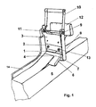
- Fig. 1 the device is shown in a perspective view. At right angles to a lateral contact part 14, a holding unit 3 is attached. At this holding unit 3, a cutting blade 1 is fixedly clamped in the lower region. In the upper region of the holding unit 3, the cutting blade 2 is fastened by means of screw connection 13 to a slider piece connected to the hand lever 10.
- the movable cutting blade 2 is not arranged parallel to the clamped cutting blade 1, but slightly obliquely fixed, so that a kind of pulling cut is performed.
- the holding unit 3 has a pivot point guide 9 for the movable cutting blade 2 moving hand lever 10.
- the hand lever 10 is held by a spring 11 against the cutting direction, wherein the spring 11 spans against the bracket of the hand lever 10 and on the other hand against the holding unit 3.
- a handle 12 is arranged on the side facing the Umleimer rotating 8 side of the holding unit 3.
- the Kantenumleimer is fixed according to the known preparation work by means of the intended adhesive on the edge surface to be glued.
- the hand lever 10 After a subsequent alignment of the position of the device and edge band is effected by the depression of the hand lever 10 against the force applied by the spring 11 of the cutting operation. Conveniently, the hand lever 10 is covered with the palm of the thumb in the thumb area, while the four remaining fingers lie around the handle 12. The pressure on the hand lever 10 is now applied by contraction of the hand.
- the device is slightly lifted after the cutting process backwards and upwards and then lifted in the direction Umleimertearing 8 of the plate 5.
- the remaining gluing end 4 is now pressed firmly onto the edge to be glued, it being possible if necessary to additionally apply glue.
Landscapes
- Life Sciences & Earth Sciences (AREA)
- Forests & Forestry (AREA)
- Engineering & Computer Science (AREA)
- Mechanical Engineering (AREA)
- Wood Science & Technology (AREA)
- Knives (AREA)
- Making Paper Articles (AREA)
- Perforating, Stamping-Out Or Severing By Means Other Than Cutting (AREA)
- Details Of Cutting Devices (AREA)
- Control And Other Processes For Unpacking Of Materials (AREA)
Description
- Die Erfindung betrifft eine tragbare Vorrichtung zum genauen Ablängen von Umleimern, welche die Schmalflächen von Möbelbauplatten oder Arbeitsplatten für den Küchenbereich u.ä. in dekorativer Form verkleiden.
Vorgesehen ist der Einsatz dieser Vorrichtung insbesondere für die manuelle Arbeit vor Ort auf Baustellen oder bei der Vorortmontage von Möbel direkt beim Kunden. - Die Schmalflächen von Möbelbauplatten oder Arbeitsplatten für den Küchenbereich u.ä. werden häufig in dekorativer Form mit dünnwandigen Umleimern aus Kunststoff oder Holzfumier verkleidet. Das Aufbringen dieser Umleimer erfolgt zum überwiegenden Teil unmittelbar bei der Herstellung der vorgenannten Platten auf Kantenumleimmaschinen. Hier sind die Ablängvorrichtungen meistens in derartigen Maschinen eingebunden.
- Bei handwerklichen Verarbeitung solcher Platten zu Möbelbaugruppen bzw. bei der individuellen Montage direkt beim Kunden müssen die mit Umleimern versehenen Platten zugeschnitten werden und die entstandenen Schnittflächen wieder umleimt werden. Dabei muss zwangsläufig der Umleimer nach dem Aufbringen auf die Schmalseite der zugeschnittenen Platte auf seine erforderliche Länge geschnitten werden.
- Diese Art des Ablängens des Umleimers erfolgt meistens von Hand mittels entsprechenden Werkzeugen, wie beispielsweise mit Rasierklingenmesser u.dgl.
Da es sich zumeist um relativ hochwertige Möbelstücke handelt, muss natürlich der bei diesem Schneidvorgang entstehende Stoß sehr genau ausgeführt sein um möglichst keine Schnittkante zu sehen. Dies erfordert ein außerordentliches handwerkliches Geschick von der ausführenden Person. Besonders sorgfältig muss dies erfolgen, wenn Umleimerende wieder mit dem Umleimeranfang zusammentrifft. Es kommt jedoch trotz aller Genauigkeit immer wieder vor, dass entweder zuwenig abgeschnitten wird, so dass der Ablängvorgang wiederholt werden muss oder dass, wenn auch nur im geringsten Umfang zu viel abgeschnitten wird und so eine unschöne sichtbare Schnittkante bzw. ein unsauberer Stoß entsteht. - Ferner kann es auch vorkommen, dass der Umleimer beim Abschneiden splittert und deshalb der Umleimer zumindest teilweise neu aufgebracht werden muss.
- In zunehmenden Maße kommen auch metallische Werkstoffe z.B. Aluminium als Umleimer zum Einsatz. Das Ablängen dieser Umleimer von Hand ist mit einem Messer kaum noch realisierbar.
- Aus der DE-U1 80 28 742 ist ein tragbares Kappgerät für Umleimer zum Bündigkappen der überstehenden Umleimerenden bekannt, bei dem zwei Anlageelemente zu einem Anlagewinkel verbunden sind, an dessen einem Ende ein quer zum Anschlagwinkel verschiebbares Kappmesser und ein Längsanschlag angeordnet ist, wobei das Kappmesser mit seiner Bewegungsbahn gegen den Anschlag geneigt an diesem angeordnet ist.
- Von Nachteil bei dieser technischen Lösung ist es, dass die Anordnung bzw. die Ausführung des Kappmessers nur ein Ablängen des Umleimers in der Form zulässt, dass beide Umleimerenden übereinander gelegt und beide Umleimer mittels des geführten Kappmessers durchgeschlagen werden müssen. Hierfür ist ein hoher Schlagkraftaufwand erforderlich, der nur ungenügend dosiert aufgebracht werden kann. So ist es von Nachteil, dass wenn der Schlagkraftaufwand zu hoch gewählt wurde, das Kappmesser in das Plattengrundmaterial eindringen und hier Schäden herbeiführen kann.
- In der DE-A1 197 00 343 wird ein Kantenumleimerschneidgerät mit Anlaufzapfen und rundem Messer offenbart, welches jedoch ausschließlich für ein Bündigschneiden des Umleimers in seiner Längsrichtung vorgesehen ist.
- Die in der DE-A1 37 17 207 angegebene Kappvorrichtung für Kantenumleimer ist maschinengebunden für eine Maschine zum Anbringen der Umleimer ausgelegt und deshalb für einen Einsatz bei der Möbelmontage direkt beim Kunden weniger geeignet.
- In der DE-A1 196 53 235 ist ein Werkzeug zum Bündigen Ablängen vom Umleimern wiedergegeben, bei welchem mehrere mit einer Auflagekante und mindestens einer Schneide versehene Platten parallel zueinander verlaufend in Form eines Blocks beweglich gelagert sind, wodurch insbesondere auf profilierten Kanten von Werkstücken aufgeleimte Umleimer abgelängt werden können, weil die Platten eine Anpassung des Schnittes an das vorgegebene Profil ermöglichen.
- Der vorliegenden Erfindung liegt die Aufgabe zu Grunde, eine verbesserte Vorrichtung für das Ablängen von Umleimern dahingehend zu schaffen, dass eine stoß- bzw. spaltfreie Verbindung der beiden Umleimerenden hergestellt werden kann.
- Erfindungsgemäß wird diese Aufgabe dadurch gelöst, dass an einer eine festgespannte Schneidklinge haltenden und die bewegliche Schneidklinge führenden Halteeinheit ein das abzulängende Umleimerende von der Platte abführendes Winkelstück befestigt ist und die untere Kante der Halteeinheit beim Schneidvorgang an dem Umleimeranfang anliegt. Das abzulängende Ende des Umleimers ist vorzugsweise in einem vorbestimmten Winkel durch die Schneidklingen geführt, so dass am Schnittbereich ein Freischnitt erfolgt und zwar derart, dass die Kante auf der Sichtseite des Umleimers die Kante auf der Unterseite überragt.
- Die Halteeinheit weist vorzugsweise eine Drehpunktführung für den die bewegliche Schneidklinge bewegenden Handhebel auf, wobei der Handhebel mittels einer Feder entgegen der Schneidrichtung gehalten wird.
- An der in Richtung Umleimeranfang weisenden Seite der Halteeinheit ist vorzugsweise ein Handgriff angeordnet.
- Das Schneidspiel, d.h. der Abstand im zusammengeführten Zustand zwischen der Schnittkante der festen Schneidklinge und der Schnittkante der beweglichen Schneidklinge ist vorzugsweise mittels einer Schraubverstellung auf die zu schneidende Materialstärke einstellbar.
- Als einer der wesentlichen Vorteile dieser erfindungsgemäßen Lösung ist die Anordnung eines Winkelstückes an der Halteeinheit,
- Das abzulängende Umleimerende wird auf diesem Winkelstück von der Platte der Schneideinheit zugeführt und dadurch wird der Schnitt unter einem bestimmten Winkel zu dem Umleimer angebracht, so dass der sonst bei einem Schnitt in glatter Ebene entstehende Spalt zwischen Umleimeranfang und Umleimerende hier vollständig vermieden wird. Anhand eines Ausführungsbeispiels soll die Erfindung näher beschrieben werden.
Es zeigt - Figur 1
- -perspektivische Ansicht der erfindungsgemäßen Vorrichtung
- Die erfindungsgemäße Vorrichtung zum genauen Ablängen von Umleimern, welche die Schmalflächen von Möbelbauplatten oder Arbeitsplatten für den Küchenbereich u.ä. in dekorativer Form verkleiden, ist vorgesehen für den Einsatz vor Ort auf Baustellen oder bei der Vorortmontage von Möbel direkt beim Kunden.
- In Fig. 1 wird die Vorrichtung in einer perspektivische Ansicht dargestellt.
Rechtwinklig zu einem seitlichen Anlageteil 14 ist eine Halteeinheit 3 befestigt. An dieser Halteeinheit 3 ist im unteren Bereich eine Schneidklinge 1 fest eingespannt angeordnet. Im oberen Bereich der Halteeinheit 3 ist die Schneidklinge 2 mittels Schraubverbindung 13 an einem mit dem Handhebel 10 verbundenen Schieberstück befestigt. In vorteilhafter Weise ist die bewegliche Schneidklinge 2 nicht parallel zur festgespannten Schneidklinge 1 angeordnet, sondern leicht schräg befestigt, so dass eine Art ziehender Schnitt ausgeführt wird. - Mit der Schraubbefestigung 13 der festgespannten Schneidklinge 1 ist es gleichzeitig möglich, den erforderlichen Schneidspalt zwischen den Schneidklingen 1 und 2 entsprechend den zu schneidenden Werkstoffen bzw. Materialdicken zu verändern.
In diesem unteren Bereich ist gleichfalls ein Winkelstück 6 vorgesehen, welches rechtwinklig an dem Anlageteil 14 befestigt ist.
Das Winkelstück 6 ist parallel zu der fest eingespannten Schneidklinge 1 angeordnet und ist in einem Winkel von etwa 15° nach unten auf die zu umleimende Platte 5 gerichtet.
Im oberen Bereich weist die Halteeinheit 3 eine Drehpunktführung 9 für den die bewegliche Schneidklinge 2 bewegenden Handhebel 10 auf. - Der Handhebel 10 wird mittels einer Feder 11 entgegen der Schneidrichtung gehalten, wobei sich die Feder 11 zum Einen gegen den Bügel des Handhebels 10 und zum Anderen gegen die Halteeinheit 3 spannt.
An der in Richtung Umleimeranfang 8 weisenden Seite der Halteeinheit 3 ist ein Handgriff 12 angeordnet. Der Kantenumleimer wird nach den an sich bekannten Vorbereitungsarbeiten mittels des vorgesehenen Klebemittels auf der zu umleimenden Kantenfläche befestigt. - In dem Bereich wo der Umleimeranfang 8 mit dem Umleimerende 4 zusammentrifft wird nun die Vorrichtung in der Form angesetzt, dass das Winkelstück 6 in Richtung des Umleimerendes 4 zeigt.
Das Anlegeteil 14 wird dabei gegen die Breitseite der Platte 5 gedrückt und die Vorrichtung auf der zu umleimenden Kante soweit in Richtung des Umleimeranfangs 8 vorgeschoben bis die untere Kante 7 der Halteeinheit 3 gegen den Umleimeranfang 8 stößt. Das Umleimerende 4 wird nun so durch die vorhandene Öffnung zwischen der festgespannten Schneidklinge 1 und der beweglichen Schneidklinge 2 geschoben, dass der Umleimer auf dem Winkelstück 6 liegt und seitlich an dem Anlegeteil 14 geführt ist. - Nach einem folgenden Ausrichten der Lage von Vorrichtung und Umleimer wird durch das Niederdrücken des Handhebels 10 gegen die von der Feder 11 aufgebrachte Kraft der Schneidvorgang bewirkt.
Günstigerweise wird dabei der Handhebel 10 mit dem Handballen im Daumenbereich umfasst, während sich die vier übrigen Finger um den Handgriff 12 legen. Der Druck auf den Handhebel 10 wird nun durch Zusammenziehen der Hand aufgebracht. - Dadurch, dass der Umleimer über das Winkelstück 6 geführt ist und so eine Art Bogen bildet , wird die abgeschnittene Länge um einen geringen Betrag größer als die eigentliche gestreckte Länge sein, so dass der sonst entstehende Spalt überbrückt wird und es entsteht eine nahezu spalt- bzw. stoßfreie Verbindung zwischen Umleimeranfang 8 und dem beschnittenen Umleimerende 4.
- Die Vorrichtung wird nach dem Schneidvorgang leicht nach rückwärts und oben angehoben und dann in Richtung Umleimeranfang 8 von der Platte 5 abgehoben.
- Das verbleibende Umleimerende 4 wird nunmehr fest auf die zu umleimende Kante aufgedrückt, wobei ggf. zusätzlich noch Klebstoff aufgebracht werden kann.
-
- 1 -
- Schneidklinge
- 2 -
- Schneidklinge
- 3 -
- Halteeinheit
- 4 -
- Umleimerende
- 5 -
- Platte
- 6 -
- Winkelstück
- 7 -
- untere Kante
- 8 -
- Umleimeranfang
- 9 -
- Drehpunktführung
- 10 -
- Handhebel
- 11 -
- Feder
- 12 -
- Handgriff
- 13 -
- Schraubverstellung
- 14 -
- Anlegeteil
Claims (5)
- Tragbare Vorrichtung zum Ablängen von Umleimern, insbesondere von Kunststoffextrusionsprofilen, welche die Schmalflächen von Möbelbauplatten oder Arbeitsplatten für den Küchenbereich u.ä. verkleiden, mit einer quer zu einem Anlageteil (14) beweglichen Schneidklinge (2), dadurch gekennzeichnet, dass an einer eine festgespannte Schneidklinge (1) haltenden und die bewegliche Schneidklinge (2) führenden Halteeinheit (3) ein das abzulängende Umleimerende (4) von der Platte (5) abführendes Winkelstück (6) befestigt ist und die untere Kante (7) der Halteeinheit (3) beim Schneidvorgang an dem Umleimeranfang (8) anliegt.
- Vorrichtung nach Anspruch 1,dadurch gekennzeichnet, dass das abzulängende Ende des Umleimers (4) in einem vorbestimmten Winkel durch die Schneidklingen (1 ;2) geführt ist, so dass am Schnittbereich ein Freischnitt erfolgt und zwar derart, dass die Kante auf der Sichtseite des Umleimers die Kante auf der Unterseite überragt.
- Vorrichtung nach Anspruch 2, dadurch gekennzeichnet, dass die Halteeinheit (3) eine Drehpunktführung (9) für den die bewegliche Schneidklinge (2) bewegenden Handhebel (10) aufweist, wobei der Handhebel (10) mittels einer Feder (11) entgegen der Schneidrichtung gehalten wird.
- Vorrichtung nach Anspruch 3, dadurch gekennzeichnet, dass an der in Richtung Umleimeranfang (8) weisenden Seite der Halteeinheit (3) ein Handgriff (12) angeordnet ist.
- Vorrichtung nach Anspruch 4, dadurch gekennzeichnet, dass das Schneidspiel, d.h. der Abstand im zusammengeführten Zustand zwischen der Schnittkante der festen Schneidklinge (1) und der Schnittkante der beweglichen Schneidklinge (2) mittels Schraubverstellung (13) auf die zu schneidende Materialstärke einstellbar ist.
Priority Applications (1)
| Application Number | Priority Date | Filing Date | Title |
|---|---|---|---|
| PL04733312T PL1626846T3 (pl) | 2003-05-26 | 2004-05-17 | Urządzenie do przycinania oklein |
Applications Claiming Priority (2)
| Application Number | Priority Date | Filing Date | Title |
|---|---|---|---|
| DE20308339U DE20308339U1 (de) | 2003-05-26 | 2003-05-26 | Vorrichtung zum Ablängen von Umleimern |
| PCT/EP2004/005261 WO2004103658A1 (de) | 2003-05-26 | 2004-05-17 | Vorrichtung zum ablängen von umleimern |
Publications (2)
| Publication Number | Publication Date |
|---|---|
| EP1626846A1 EP1626846A1 (de) | 2006-02-22 |
| EP1626846B1 true EP1626846B1 (de) | 2006-08-30 |
Family
ID=27798569
Family Applications (1)
| Application Number | Title | Priority Date | Filing Date |
|---|---|---|---|
| EP04733312A Expired - Lifetime EP1626846B1 (de) | 2003-05-26 | 2004-05-17 | Vorrichtung zum ablängen von umleimern |
Country Status (7)
| Country | Link |
|---|---|
| EP (1) | EP1626846B1 (de) |
| AT (1) | ATE337896T1 (de) |
| DE (2) | DE20308339U1 (de) |
| DK (1) | DK1626846T3 (de) |
| ES (1) | ES2271891T3 (de) |
| PL (1) | PL1626846T3 (de) |
| WO (1) | WO2004103658A1 (de) |
Families Citing this family (1)
| Publication number | Priority date | Publication date | Assignee | Title |
|---|---|---|---|---|
| ES2350116T3 (es) | 2006-05-12 | 2011-01-18 | Rehau Ag + Co | Dispositivo para corte a medida de cubrecantos. |
Family Cites Families (8)
| Publication number | Priority date | Publication date | Assignee | Title |
|---|---|---|---|---|
| US3079688A (en) * | 1961-04-10 | 1963-03-05 | Harry H Ryan | Linoleum cutter |
| US3514855A (en) * | 1967-12-26 | 1970-06-02 | Kinkead Industries | Trimmer for trimming carpeting to a reference edge |
| DE1915600C2 (de) | 1969-03-27 | 1984-04-26 | Enka Ag, 5600 Wuppertal | Schneidvorrichtung für Maschinen mit hin- und hergehender Messerbewegung zum Schneiden von Faserkabeln, Folien u.dgl. |
| DE8028742U1 (de) * | 1980-10-29 | 1981-02-26 | Noizet, Erwin, 7443 Frickenhausen | Tragbares kappgeraet fuer umleimer |
| DE3717207A1 (de) * | 1987-05-22 | 1988-12-08 | Reich Spezialmaschinen Gmbh | Kappvorrichtung fuer kantenanleimmaschinen |
| DE19653235A1 (de) * | 1996-12-20 | 1998-06-25 | Poenopp Adalbert | Werkzeug zum bündigen Ablängen von Umleimern |
| DE19700343C2 (de) * | 1997-01-08 | 1999-04-08 | Ralf Mattiat | Kantenschneider |
| JP2001353688A (ja) | 2000-06-12 | 2001-12-25 | Toshiba Corp | 半導体パッケージ用テープの切断金型及び半導体装置の製造方法 |
-
2003
- 2003-05-26 DE DE20308339U patent/DE20308339U1/de not_active Expired - Lifetime
-
2004
- 2004-05-17 WO PCT/EP2004/005261 patent/WO2004103658A1/de not_active Ceased
- 2004-05-17 EP EP04733312A patent/EP1626846B1/de not_active Expired - Lifetime
- 2004-05-17 DK DK04733312T patent/DK1626846T3/da active
- 2004-05-17 AT AT04733312T patent/ATE337896T1/de active
- 2004-05-17 PL PL04733312T patent/PL1626846T3/pl unknown
- 2004-05-17 ES ES04733312T patent/ES2271891T3/es not_active Expired - Lifetime
- 2004-05-17 DE DE502004001363T patent/DE502004001363D1/de not_active Expired - Lifetime
Also Published As
| Publication number | Publication date |
|---|---|
| DE20308339U1 (de) | 2003-08-28 |
| ES2271891T3 (es) | 2007-04-16 |
| DK1626846T3 (da) | 2007-01-08 |
| PL1626846T3 (pl) | 2006-12-29 |
| DE502004001363D1 (de) | 2006-10-12 |
| EP1626846A1 (de) | 2006-02-22 |
| WO2004103658A1 (de) | 2004-12-02 |
| ATE337896T1 (de) | 2006-09-15 |
Similar Documents
| Publication | Publication Date | Title |
|---|---|---|
| EP0437753B1 (de) | Verfahren und Vorrichtung zum Trennen von beschichteten Werkstücken aus Holz oder dgl. | |
| DE20203938U1 (de) | Bearbeitungsmaschine zum wenigstens teilweisen konturenabhängigen Ausschneiden oder Fräsen | |
| DE10323266B3 (de) | Kantenanleimaggregat für eine programmgesteuerte Maschine | |
| EP1626846B1 (de) | Vorrichtung zum ablängen von umleimern | |
| EP1990152B1 (de) | Kantenanleimaggregat und Verfahren zum Anleimen von Kantenmaterial | |
| EP0332906B1 (de) | Gehrungslehre | |
| DE2720762A1 (de) | Verfahren und vorrichtung zum verarbeiten von rundholz zu schnittholz | |
| EP1854602B1 (de) | Vorrichtung zum Ablängen von Umleimern | |
| DE2706149B2 (de) | Verfahren zur Ermittlung der wirtschaftlichsten Schnittführung bei Besäumanlagen für Bretter o.dgl | |
| DE2951078C1 (de) | Gehrungslade | |
| DE1528061A1 (de) | Verfahren und Vorrichtung zum Bilden von Nuten in geschichtetem Bahnmaterial | |
| DE2647331A1 (de) | Geraet zum schneiden von fliesen aus fayence, steingut oder anderem keramischen material | |
| EP3278940B1 (de) | Vorrichtung zur verwendung beim trockenausbau | |
| DE2225417A1 (de) | ||
| DE1703446B2 (de) | Kappvorrichtung für Furnierkanten | |
| EP0143882B1 (de) | Verfahren zur Anbringung eines mit einem Deckstreifen beschichteten, soft-geformten Kantenprofils an plattenförmige Werkstücke und Vorrichtung zum Abschneiden des Deckstreifens | |
| DE615950C (de) | Auf dem Steg einer Schraubzwinge verschiebbare und feststellbare Klemmbacke zum Verleimen von Eckverbindungen | |
| DE3336275C2 (de) | Verfahren zur Anbringung eines mit einem Deckstreifen beschichteten, soft-geformten Kantenprofils an plattenförmige Werkstücke und Vorrichtung zum Abschneiden des Deckstreifens | |
| DE968366C (de) | Kantenleimvorrichtung | |
| DE643620C (de) | Vorrichtung zum Schaeften von Furnieren | |
| EP0683005A1 (de) | Werkstückhaltevorrichtung für Unterflur-Zugkreissägen | |
| DE71998C (de) | Vorrichtung zum Abschneiden gleichmäfsig breiter Streifen von Papierbogen und Anlegen derselben an Papptafeln | |
| DE603470C (de) | Handschneidegeraet | |
| DE818148C (de) | Blechschere | |
| DE8028742U1 (de) | Tragbares kappgeraet fuer umleimer |
Legal Events
| Date | Code | Title | Description |
|---|---|---|---|
| PUAI | Public reference made under article 153(3) epc to a published international application that has entered the european phase |
Free format text: ORIGINAL CODE: 0009012 |
|
| 17P | Request for examination filed |
Effective date: 20051117 |
|
| AK | Designated contracting states |
Kind code of ref document: A1 Designated state(s): AT BE BG CH CY CZ DE DK EE ES FI FR GB GR HU IE IT LI LU MC NL PL PT RO SE SI SK TR |
|
| AX | Request for extension of the european patent |
Extension state: HR LT LV |
|
| GRAP | Despatch of communication of intention to grant a patent |
Free format text: ORIGINAL CODE: EPIDOSNIGR1 |
|
| RAX | Requested extension states of the european patent have changed |
Extension state: HR Payment date: 20051117 Extension state: LV Payment date: 20051117 Extension state: LT Payment date: 20051117 |
|
| GRAS | Grant fee paid |
Free format text: ORIGINAL CODE: EPIDOSNIGR3 |
|
| GRAA | (expected) grant |
Free format text: ORIGINAL CODE: 0009210 |
|
| AK | Designated contracting states |
Kind code of ref document: B1 Designated state(s): AT BE BG CH CY CZ DE DK EE ES FI FR GB GR HU IE IT LI LU MC NL PL PT RO SE SI SK TR |
|
| AX | Request for extension of the european patent |
Extension state: HR LT LV |
|
| PG25 | Lapsed in a contracting state [announced via postgrant information from national office to epo] |
Ref country code: IE Free format text: LAPSE BECAUSE OF FAILURE TO SUBMIT A TRANSLATION OF THE DESCRIPTION OR TO PAY THE FEE WITHIN THE PRESCRIBED TIME-LIMIT Effective date: 20060830 Ref country code: IT Free format text: LAPSE BECAUSE OF FAILURE TO SUBMIT A TRANSLATION OF THE DESCRIPTION OR TO PAY THE FEE WITHIN THE PRESCRIBED TIME-LIMIT;WARNING: LAPSES OF ITALIAN PATENTS WITH EFFECTIVE DATE BEFORE 2007 MAY HAVE OCCURRED AT ANY TIME BEFORE 2007. THE CORRECT EFFECTIVE DATE MAY BE DIFFERENT FROM THE ONE RECORDED. Effective date: 20060830 Ref country code: FI Free format text: LAPSE BECAUSE OF FAILURE TO SUBMIT A TRANSLATION OF THE DESCRIPTION OR TO PAY THE FEE WITHIN THE PRESCRIBED TIME-LIMIT Effective date: 20060830 Ref country code: SI Free format text: LAPSE BECAUSE OF FAILURE TO SUBMIT A TRANSLATION OF THE DESCRIPTION OR TO PAY THE FEE WITHIN THE PRESCRIBED TIME-LIMIT Effective date: 20060830 |
|
| REG | Reference to a national code |
Ref country code: GB Ref legal event code: FG4D Free format text: NOT ENGLISH |
|
| REG | Reference to a national code |
Ref country code: CH Ref legal event code: EP |
|
| REG | Reference to a national code |
Ref country code: IE Ref legal event code: FG4D Free format text: LANGUAGE OF EP DOCUMENT: GERMAN |
|
| REF | Corresponds to: |
Ref document number: 502004001363 Country of ref document: DE Date of ref document: 20061012 Kind code of ref document: P |
|
| REG | Reference to a national code |
Ref country code: RO Ref legal event code: EPE |
|
| REG | Reference to a national code |
Ref country code: GR Ref legal event code: EP Ref document number: 20060403715 Country of ref document: GR |
|
| PG25 | Lapsed in a contracting state [announced via postgrant information from national office to epo] |
Ref country code: SE Free format text: LAPSE BECAUSE OF FAILURE TO SUBMIT A TRANSLATION OF THE DESCRIPTION OR TO PAY THE FEE WITHIN THE PRESCRIBED TIME-LIMIT Effective date: 20061130 |
|
| GBT | Gb: translation of ep patent filed (gb section 77(6)(a)/1977) |
Effective date: 20061109 |
|
| REG | Reference to a national code |
Ref country code: DK Ref legal event code: T3 |
|
| PG25 | Lapsed in a contracting state [announced via postgrant information from national office to epo] |
Ref country code: PT Free format text: LAPSE BECAUSE OF FAILURE TO SUBMIT A TRANSLATION OF THE DESCRIPTION OR TO PAY THE FEE WITHIN THE PRESCRIBED TIME-LIMIT Effective date: 20070212 |
|
| LTIE | Lt: invalidation of european patent or patent extension |
Effective date: 20060830 |
|
| ET | Fr: translation filed | ||
| REG | Reference to a national code |
Ref country code: ES Ref legal event code: FG2A Ref document number: 2271891 Country of ref document: ES Kind code of ref document: T3 |
|
| REG | Reference to a national code |
Ref country code: IE Ref legal event code: FD4D |
|
| PGFP | Annual fee paid to national office [announced via postgrant information from national office to epo] |
Ref country code: RO Payment date: 20070516 Year of fee payment: 4 |
|
| PGFP | Annual fee paid to national office [announced via postgrant information from national office to epo] |
Ref country code: DK Payment date: 20070518 Year of fee payment: 4 |
|
| PLBE | No opposition filed within time limit |
Free format text: ORIGINAL CODE: 0009261 |
|
| STAA | Information on the status of an ep patent application or granted ep patent |
Free format text: STATUS: NO OPPOSITION FILED WITHIN TIME LIMIT |
|
| 26N | No opposition filed |
Effective date: 20070531 |
|
| PG25 | Lapsed in a contracting state [announced via postgrant information from national office to epo] |
Ref country code: MC Free format text: LAPSE BECAUSE OF NON-PAYMENT OF DUE FEES Effective date: 20070531 |
|
| PG25 | Lapsed in a contracting state [announced via postgrant information from national office to epo] |
Ref country code: EE Free format text: LAPSE BECAUSE OF FAILURE TO SUBMIT A TRANSLATION OF THE DESCRIPTION OR TO PAY THE FEE WITHIN THE PRESCRIBED TIME-LIMIT Effective date: 20060830 |
|
| PGFP | Annual fee paid to national office [announced via postgrant information from national office to epo] |
Ref country code: CH Payment date: 20080410 Year of fee payment: 5 Ref country code: CZ Payment date: 20080515 Year of fee payment: 5 |
|
| PGFP | Annual fee paid to national office [announced via postgrant information from national office to epo] |
Ref country code: SK Payment date: 20080414 Year of fee payment: 5 |
|
| PGFP | Annual fee paid to national office [announced via postgrant information from national office to epo] |
Ref country code: BE Payment date: 20080410 Year of fee payment: 5 Ref country code: IT Payment date: 20080423 Year of fee payment: 5 Ref country code: BG Payment date: 20080415 Year of fee payment: 5 Ref country code: PL Payment date: 20080404 Year of fee payment: 5 |
|
| PGRI | Patent reinstated in contracting state [announced from national office to epo] |
Ref country code: IT Effective date: 20080601 |
|
| PGFP | Annual fee paid to national office [announced via postgrant information from national office to epo] |
Ref country code: NL Payment date: 20080409 Year of fee payment: 5 |
|
| PGFP | Annual fee paid to national office [announced via postgrant information from national office to epo] |
Ref country code: FR Payment date: 20080410 Year of fee payment: 5 |
|
| PGFP | Annual fee paid to national office [announced via postgrant information from national office to epo] |
Ref country code: GB Payment date: 20080414 Year of fee payment: 5 |
|
| REG | Reference to a national code |
Ref country code: DK Ref legal event code: EBP |
|
| PG25 | Lapsed in a contracting state [announced via postgrant information from national office to epo] |
Ref country code: DK Free format text: LAPSE BECAUSE OF NON-PAYMENT OF DUE FEES Effective date: 20080531 |
|
| PGFP | Annual fee paid to national office [announced via postgrant information from national office to epo] |
Ref country code: GR Payment date: 20080423 Year of fee payment: 5 |
|
| PG25 | Lapsed in a contracting state [announced via postgrant information from national office to epo] |
Ref country code: RO Free format text: LAPSE BECAUSE OF NON-PAYMENT OF DUE FEES Effective date: 20080517 |
|
| PG25 | Lapsed in a contracting state [announced via postgrant information from national office to epo] |
Ref country code: CY Free format text: LAPSE BECAUSE OF FAILURE TO SUBMIT A TRANSLATION OF THE DESCRIPTION OR TO PAY THE FEE WITHIN THE PRESCRIBED TIME-LIMIT Effective date: 20060830 Ref country code: LU Free format text: LAPSE BECAUSE OF NON-PAYMENT OF DUE FEES Effective date: 20070517 |
|
| PG25 | Lapsed in a contracting state [announced via postgrant information from national office to epo] |
Ref country code: TR Free format text: LAPSE BECAUSE OF FAILURE TO SUBMIT A TRANSLATION OF THE DESCRIPTION OR TO PAY THE FEE WITHIN THE PRESCRIBED TIME-LIMIT Effective date: 20060830 Ref country code: HU Free format text: LAPSE BECAUSE OF FAILURE TO SUBMIT A TRANSLATION OF THE DESCRIPTION OR TO PAY THE FEE WITHIN THE PRESCRIBED TIME-LIMIT Effective date: 20070301 |
|
| BERE | Be: lapsed |
Owner name: REHAU A.G. + CO Effective date: 20090531 |
|
| REG | Reference to a national code |
Ref country code: CH Ref legal event code: PL |
|
| GBPC | Gb: european patent ceased through non-payment of renewal fee |
Effective date: 20090517 |
|
| PG25 | Lapsed in a contracting state [announced via postgrant information from national office to epo] |
Ref country code: LI Free format text: LAPSE BECAUSE OF NON-PAYMENT OF DUE FEES Effective date: 20090531 Ref country code: CZ Free format text: LAPSE BECAUSE OF NON-PAYMENT OF DUE FEES Effective date: 20090517 Ref country code: CH Free format text: LAPSE BECAUSE OF NON-PAYMENT OF DUE FEES Effective date: 20090531 |
|
| NLV4 | Nl: lapsed or anulled due to non-payment of the annual fee |
Effective date: 20091201 |
|
| REG | Reference to a national code |
Ref country code: SK Ref legal event code: MM4A Ref document number: E 1227 Country of ref document: SK Effective date: 20090517 |
|
| PG25 | Lapsed in a contracting state [announced via postgrant information from national office to epo] |
Ref country code: NL Free format text: LAPSE BECAUSE OF NON-PAYMENT OF DUE FEES Effective date: 20091201 Ref country code: SK Free format text: LAPSE BECAUSE OF NON-PAYMENT OF DUE FEES Effective date: 20090517 |
|
| REG | Reference to a national code |
Ref country code: FR Ref legal event code: ST Effective date: 20100129 |
|
| PG25 | Lapsed in a contracting state [announced via postgrant information from national office to epo] |
Ref country code: FR Free format text: LAPSE BECAUSE OF NON-PAYMENT OF DUE FEES Effective date: 20090602 |
|
| PG25 | Lapsed in a contracting state [announced via postgrant information from national office to epo] |
Ref country code: GB Free format text: LAPSE BECAUSE OF NON-PAYMENT OF DUE FEES Effective date: 20090517 |
|
| PG25 | Lapsed in a contracting state [announced via postgrant information from national office to epo] |
Ref country code: BE Free format text: LAPSE BECAUSE OF NON-PAYMENT OF DUE FEES Effective date: 20090531 Ref country code: GR Free format text: LAPSE BECAUSE OF NON-PAYMENT OF DUE FEES Effective date: 20091202 |
|
| REG | Reference to a national code |
Ref country code: PL Ref legal event code: LAPE |
|
| PG25 | Lapsed in a contracting state [announced via postgrant information from national office to epo] |
Ref country code: PL Free format text: LAPSE BECAUSE OF NON-PAYMENT OF DUE FEES Effective date: 20090517 |
|
| PG25 | Lapsed in a contracting state [announced via postgrant information from national office to epo] |
Ref country code: IT Free format text: LAPSE BECAUSE OF NON-PAYMENT OF DUE FEES Effective date: 20090517 Ref country code: BG Free format text: LAPSE BECAUSE OF FAILURE TO SUBMIT A TRANSLATION OF THE DESCRIPTION OR TO PAY THE FEE WITHIN THE PRESCRIBED TIME-LIMIT Effective date: 20090531 |
|
| PGFP | Annual fee paid to national office [announced via postgrant information from national office to epo] |
Ref country code: AT Payment date: 20140513 Year of fee payment: 11 Ref country code: ES Payment date: 20140516 Year of fee payment: 11 Ref country code: DE Payment date: 20140531 Year of fee payment: 11 |
|
| REG | Reference to a national code |
Ref country code: DE Ref legal event code: R119 Ref document number: 502004001363 Country of ref document: DE |
|
| REG | Reference to a national code |
Ref country code: AT Ref legal event code: MM01 Ref document number: 337896 Country of ref document: AT Kind code of ref document: T Effective date: 20150517 |
|
| PG25 | Lapsed in a contracting state [announced via postgrant information from national office to epo] |
Ref country code: AT Free format text: LAPSE BECAUSE OF NON-PAYMENT OF DUE FEES Effective date: 20150517 |
|
| PG25 | Lapsed in a contracting state [announced via postgrant information from national office to epo] |
Ref country code: DE Free format text: LAPSE BECAUSE OF NON-PAYMENT OF DUE FEES Effective date: 20151201 |
|
| REG | Reference to a national code |
Ref country code: ES Ref legal event code: FD2A Effective date: 20160906 |
|
| PG25 | Lapsed in a contracting state [announced via postgrant information from national office to epo] |
Ref country code: ES Free format text: LAPSE BECAUSE OF NON-PAYMENT OF DUE FEES Effective date: 20150518 |