EP1627706A1 - Outil abrasif, méthode de sa production / restauration et procédé de meulage par point - Google Patents
Outil abrasif, méthode de sa production / restauration et procédé de meulage par point Download PDFInfo
- Publication number
- EP1627706A1 EP1627706A1 EP05254935A EP05254935A EP1627706A1 EP 1627706 A1 EP1627706 A1 EP 1627706A1 EP 05254935 A EP05254935 A EP 05254935A EP 05254935 A EP05254935 A EP 05254935A EP 1627706 A1 EP1627706 A1 EP 1627706A1
- Authority
- EP
- European Patent Office
- Prior art keywords
- tool
- abrasive
- workpiece
- recess
- machining
- Prior art date
- Legal status (The legal status is an assumption and is not a legal conclusion. Google has not performed a legal analysis and makes no representation as to the accuracy of the status listed.)
- Granted
Links
Images

Classifications
-
- B—PERFORMING OPERATIONS; TRANSPORTING
- B24—GRINDING; POLISHING
- B24D—TOOLS FOR GRINDING, BUFFING OR SHARPENING
- B24D7/00—Bonded abrasive wheels, or wheels with inserted abrasive blocks, designed for acting otherwise than only by their periphery, e.g. by the front face; Bushings or mountings therefor
-
- B—PERFORMING OPERATIONS; TRANSPORTING
- B24—GRINDING; POLISHING
- B24D—TOOLS FOR GRINDING, BUFFING OR SHARPENING
- B24D18/00—Manufacture of grinding tools or other grinding devices, e.g. wheels, not otherwise provided for
- B24D18/0018—Manufacture of grinding tools or other grinding devices, e.g. wheels, not otherwise provided for by electrolytic deposition
-
- Y—GENERAL TAGGING OF NEW TECHNOLOGICAL DEVELOPMENTS; GENERAL TAGGING OF CROSS-SECTIONAL TECHNOLOGIES SPANNING OVER SEVERAL SECTIONS OF THE IPC; TECHNICAL SUBJECTS COVERED BY FORMER USPC CROSS-REFERENCE ART COLLECTIONS [XRACs] AND DIGESTS
- Y10—TECHNICAL SUBJECTS COVERED BY FORMER USPC
- Y10T—TECHNICAL SUBJECTS COVERED BY FORMER US CLASSIFICATION
- Y10T279/00—Chucks or sockets
- Y10T279/16—Longitudinal screw clamp
-
- Y—GENERAL TAGGING OF NEW TECHNOLOGICAL DEVELOPMENTS; GENERAL TAGGING OF CROSS-SECTIONAL TECHNOLOGIES SPANNING OVER SEVERAL SECTIONS OF THE IPC; TECHNICAL SUBJECTS COVERED BY FORMER USPC CROSS-REFERENCE ART COLLECTIONS [XRACs] AND DIGESTS
- Y10—TECHNICAL SUBJECTS COVERED BY FORMER USPC
- Y10T—TECHNICAL SUBJECTS COVERED BY FORMER US CLASSIFICATION
- Y10T407/00—Cutters, for shaping
- Y10T407/19—Rotary cutting tool
- Y10T407/1946—Face or end mill
-
- Y—GENERAL TAGGING OF NEW TECHNOLOGICAL DEVELOPMENTS; GENERAL TAGGING OF CROSS-SECTIONAL TECHNOLOGIES SPANNING OVER SEVERAL SECTIONS OF THE IPC; TECHNICAL SUBJECTS COVERED BY FORMER USPC CROSS-REFERENCE ART COLLECTIONS [XRACs] AND DIGESTS
- Y10—TECHNICAL SUBJECTS COVERED BY FORMER USPC
- Y10T—TECHNICAL SUBJECTS COVERED BY FORMER US CLASSIFICATION
- Y10T407/00—Cutters, for shaping
- Y10T407/26—Cutters, for shaping comprising cutting edge bonded to tool shank
Definitions
- the invention relates to machining. More particularly, the invention relates to superabrasive machining of metal alloy articles
- One aspect of the invention involves a tool for use in an abrasive machining process.
- a body extends along a central longitudinal axis from a first end to a tip end.
- An abrasive material is located on the tip end.
- a central recess is formed in the tip end.
- the tool may have a number of additional recesses extending from the central recess.
- the additional recesses may be elongate recesses extending generally toward the first end.
- the elongate recesses may each have a recess length and may be partially circumferentially oriented and partially longitudinally oriented along a major portion of such recess length. There may be 2-4 such recesses.
- the body may include a tip end protuberance.
- the body may include a threaded portion for engaging a machine, a flange having a pair of flats for receiving a wrench, and a shaft extending tipward from the flange.
- the abrasive may comprise a coating.
- the abrasive may be selected from the group consisting of plated cubic boron nitride, vitrified cubic boron nitride, diamond, silicon carbide, and aluminum oxide.
- the tool may be combined with a machine rotating the tool about the longitudinal axis at a speed in excess of 10,000 revolutions per minute.
- a pilot hole is drilled in the tip end.
- the pilot hole is counterbored.
- the abrasive is applied as a coating.
- the coating may be adjacent the recesses and may be along the recesses.
- a number of additional recesses may be machined extending from the central recess.
- the additional recesses may be elongate and extend generally toward the first end.
- a tool having a tip grinding surface coated with an abrasive and having a central tip recess.
- the tool is oriented relative to a surface of the workpiece so that there is contact between the surface and the grinding surface.
- a part is formed by removing material at the contact by rotating the tool about the central longitudinal axis.
- the tool may be rotated at a speed in the range of 40,000 to 120,000 revolutions per minute.
- the longitudinal axis may be reoriented relative to the workpiece while machining the workpiece.
- the workpiece may comprise a component selected from the group consisting of integrally bladed disks and turbine engine case components.
- the machining may form an interblade floor of the disk or an exterior pocket of the component.
- the workpiece may comprise or may consist essentially of a nickel- or cobalt-based superalloy or titanium alloy.
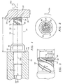
- FIG. 1 shows an abrasive quill 20 mounted in a multi-axis machine tool spindle 22.
- the machine tool rotates the quill about a central longitudinal axis 500 and translates the quill in one or more directions (e.g., a direction of translation 502) to machine a workpiece 24. Exemplary rotation is in a direction 504 (FIG. 3) at a speed in excess of 10,000rpm (e.g., in the range of 40,000rpm-90,000rpm).
- the traversal of the quill removes material below a surface 25 and leaves a cut surface 26 on the workpiece.
- the machine tool may further reorient the axis 500. Alternatively or additionally, the machine tool may reposition or reorient the workpiece.
- the exemplary quill 20 includes a metallic body extending from an aft end 30 to a front (tip) end 32. An abrasive coating 34 on the tip end provides cutting effectiveness.
- the exemplary quill includes a threaded portion 36 for mating by threaded engagement to a correspondingly threaded portion of a central aperture 38 of the spindle 22.
- an unthreaded cylindrical portion 40 fits with close tolerance to a corresponding unthreaded portion of the aperture 38 to maintain precise commonality of the quill/spindle/rotation axis 500.
- a wrenching flange 42 is forward (tipward) of the unthreaded portion 40 and has a radially-extending aft surface 44 abutting a fore surface 46 of the spindle.
- the exemplary flange 42 has at least a pair of parallel opposite wrench flats 48 for installing and removing the quill via the threaded engagement.
- features other than the threaded shaft and wrenching flange may be provided for use with tools having different quill interfaces such as are used with automatic tool changers.
- a shaft 50 extends generally forward from the flange 42 to the tip 32.
- the shaft 50 includes a proximal portion 52, a toroid-like tip protuberance portion 54, and an intermediate portion 56.
- the proximal portion 52 is relatively longer than the combined protuberance 54 and intermediate portion 56 and of generally relatively greater diameter than at least the intermediate portion and, in the exemplary embodiment, the protuberance 54.
- a shoulder 58 e.g., beveled
- the tip protuberance 54 is sufficiently small to make the required cut features.
- the intermediate portion 56 is advantageously narrow enough and long enough to avoid interfering with other portions of the part during the machinging.
- the relative thickness of the proximal portion 52 provides strength.
- the length of the proximal portion 52 (combined with the lengths of intermediate portion and protuberance) provides the desired separation of the tip from the tool spindle. Such separation may be required to make the desired cut while avoiding interference between the spindle and any portion of the part that might otherwise interfere with the spindle.
- the tip 32 (FIG. 2) includes a central recess 60 surrounded by a rim 62.
- the protuberance 54 has a concave transition 64 to the intermediate portion 56.
- a convex portion 66 extends forward thereof through an outboardmost location 68 and back radially inward to form the rim 62. From the rim, the surface continues to extend inward and aftward along a portion 70 defining a relatively broad forward portion of the recess 60.
- the forward portion of the recess has a generally radially-extending annular base 72.
- the recess includes a smaller diameter pilot hole portion 74 extending aftward from the base 72.
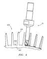
- FIG. 4 shows exemplary positioning of the quill 20 during one stage of the machining of an integrally bladed rotor 200 (IBR, also known as a blisk).
- IBR integrally bladed rotor 200
- the unitarily-formed blisk 200 has a hub 202 from which a circumferential array of blades 204 radially extend.
- the quill 20 is shown grinding an interblade floor 206 between adjacent blades 204.
- the same or a different quill may be used to machine surface contours (e.g., pressure side concavity and suction side convexity) of the blades. Traversal at or near normal to the quill axis permits machining of the floor 206 in a relatively small number of passes (e.g., contrasted with a more sharply tipped quill at a greater angle off normal machining very narrow, highly concave passes which must be very closely spaced to achieve near flatness and which may require substantial additional smoothing.
- surface contours e.g., pressure side concavity and suction side convexity
- FIG. 5 shows the quill 20 machining one of several pockets 250 in a titanium alloy duct segment 252.
- the exemplary segment 252 is unitarily formed including inboard (interior) and outboard (exterior) surfaces 254 and 256.
- the exemplary segment extends between upstream (fore) and downstream (aft) ends 258 and 260.
- the segment also has a pair of longitudinal ends 262.
- the exemplary segment further includes apertures / ports 264.
- the machining of the pockets 250 in the exemplary segment leaves an outwardly extending perimeter rib 266, intermediate structural reinforcing ribs 268 (e.g., spanning between portions of the perimeter rib 266), and aperture-circumscribing ribs 270.
- the ribs 270 may define bosses with a mounting of conduits, instruments, actuators, or other components which may pass through the segment.
- Use of the exemplary quill and traversal at or near normal to its axis may provide convenient machining of relatively flat pocket floors along the exterior surface 256 and relatively narrow (especially narrow-based) ribs for substantial lightening of the segment.
- An additional feature of the exemplary quill 20 is the presence of elongate recesses 90, which may serve to help evacuate grinding debris and/or may help to improve coolant flow to the grinding zone.
- the recesses 90 extend from the central recess 60 through the rim 62 and spiral along the intermediate portion 56.
- the exemplary recesses 90 have radially-extending root portions 92 within the recess 60 leading to arcuate portions 94 cutting through and castellating the rim 62 and then spiraling along the intermediate portion 56.
- the exemplary spiraling may have tangential and longitudinal components that differ along the length of the recesses 90 so as to not be a helix.
- the basic quill body is machined (e.g., via one or more lathe turning steps or grinding steps) from steel stock, including cutting the threads on the portion 36 and drilling the pilot hole and counterbore at the tip.
- the elongate recesses may then be formed (e.g., by end milling).
- There may be heat and/or mechanical surface treatment steps.
- the abrasive may then be applied as a coating (e.g., via electroplating).
- Exemplary superabrasive material may be selected from the group of cubic boron nitride (e.g., plated or vitrified), diamond (particularly useful for machining titanium alloys), silicon carbide, and aluminum oxide.
- the exemplary superabrasive material may have a grit size in the range of 40/45 to 325/400 depending on the depth of the cut and the required surface finish (e.g., 10 ⁇ in or finer).
- a mask may be applied prior to said coating and removed thereafter to protect areas where coating is not desired.
- the mask may confine the coating to the tip protuberance portion 54.
- the mask may also cover the portions of the recesses interrupting the protuberance and may cover the counterbore to keep these areas uncoated so as to maximize the capacity for coolant flow through these areas.
- the as-applied coating may be dressed to improve machining precision.
- Alternative orders are possible, for example including applying the abrasive before forming the elongate recesses.
- the coating may be cleaned and/or redressed (e.g., via a diamond wheel) at one or more times.
- additional coating may be applied (e.g., optionally after a removal of some or all remaining used/worn/contaminated coating).
- additional coating may be applied (e.g., optionally after a removal of some or all remaining used/worn/contaminated coating).
- additional coating may be applied (e.g., optionally after a removal of some or all remaining used/worn/contaminated coating).
- additional coating may be applied (e.g., optionally after a removal of some or all remaining used/worn/contaminated coating).
- the coating thickness in these areas would not be too great so as to interfere with their operation.
- these areas could be masked during the recoating process.
- An advantageous process removes all the abrasive coating (e.g., via chemical means) from the quill prior to application of the replacement coating.
- An exemplary projecting length L of the quill forward of the spindle is 57mm, more broadly, in a range of 40-80mm.
- An exemplary protuberance diameter D is 14mm, more broadly 8-20mm.
- An exemplary recess diameter D 1 is 20-80% of D, more narrowly 30-70%.
- An exemplary elongate recess width W is 1.5mm, more broadly 0.8-3.0mm.
- An exemplary elongate recess depth is 30%-70% of the width (e.g., 0.8mm, more broadly 0.4-2.0mm).
- the rim may be longitudinally radiused with an exemplary radius of curvature of 1.6mm, more broadly 0.5mm-3.0mm (e.g., at the location 68 and forward therefrom).
Landscapes
- Engineering & Computer Science (AREA)
- Mechanical Engineering (AREA)
- Manufacturing & Machinery (AREA)
- Polishing Bodies And Polishing Tools (AREA)
- Grinding And Polishing Of Tertiary Curved Surfaces And Surfaces With Complex Shapes (AREA)
- Finish Polishing, Edge Sharpening, And Grinding By Specific Grinding Devices (AREA)
Applications Claiming Priority (1)
| Application Number | Priority Date | Filing Date | Title |
|---|---|---|---|
| US10/918,937 US7927189B2 (en) | 2004-08-16 | 2004-08-16 | Superabrasive tool |
Publications (2)
| Publication Number | Publication Date |
|---|---|
| EP1627706A1 true EP1627706A1 (fr) | 2006-02-22 |
| EP1627706B1 EP1627706B1 (fr) | 2008-11-12 |
Family
ID=35385722
Family Applications (1)
| Application Number | Title | Priority Date | Filing Date |
|---|---|---|---|
| EP05254935A Expired - Lifetime EP1627706B1 (fr) | 2004-08-16 | 2005-08-08 | Outil abrasif, méthode de sa production / restauration et procédé de meulage par point |
Country Status (6)
| Country | Link |
|---|---|
| US (2) | US7927189B2 (fr) |
| EP (1) | EP1627706B1 (fr) |
| JP (1) | JP2006055990A (fr) |
| CN (1) | CN1736663A (fr) |
| AT (1) | ATE413946T1 (fr) |
| DE (1) | DE602005010945D1 (fr) |
Cited By (3)
| Publication number | Priority date | Publication date | Assignee | Title |
|---|---|---|---|---|
| US7704021B2 (en) | 2008-02-20 | 2010-04-27 | Rolls-Royce Deutschland Ltd & Co Kg | Method and tooling for machining the annulus of gas-turbine rotor provided with integrally formed-on blades |
| EP2050927A3 (fr) * | 2007-10-16 | 2012-03-21 | United Technologies Corporation | Procédé de restauration de contour d'extrémité de surface portante |
| EP2050926A3 (fr) * | 2007-10-16 | 2012-03-21 | United Technologies Corporation | Procédé de restauration de contour de surface portante sur des rotors à aubage intégral |
Families Citing this family (16)
| Publication number | Priority date | Publication date | Assignee | Title |
|---|---|---|---|---|
| US7181169B2 (en) * | 2003-02-15 | 2007-02-20 | Lg Electronics Inc. | Controlling apparatus and method of mobile communication terminal using electrostatic detection |
| GB2427843B (en) * | 2005-10-24 | 2008-05-07 | C4 Carbides Ltd | Drill bit |
| US7896728B2 (en) * | 2007-09-13 | 2011-03-01 | United Technologies Corporation | Machining methods using superabrasive tool |
| KR20100138359A (ko) * | 2009-06-25 | 2010-12-31 | 신한다이아몬드공업 주식회사 | 다이아몬드 공구 |
| US8567059B2 (en) * | 2009-07-10 | 2013-10-29 | Pratt & Whitney Canada Corp. | Process for forming a firtree slot in a disc of a rotor of a gas turbine engine |
| FR2949204B1 (fr) * | 2009-08-21 | 2011-10-14 | Snecma | Machine d'usinage pour cmc par fraisage et abrasion par ultrasons |
| US20110306275A1 (en) * | 2010-06-13 | 2011-12-15 | Nicolson Matthew D | Component finishing tool |
| CN102764910A (zh) * | 2011-05-03 | 2012-11-07 | 富泰华工业(深圳)有限公司 | 成型铣刀 |
| US9193111B2 (en) * | 2012-07-02 | 2015-11-24 | United Technologies Corporation | Super polish masking of integrally bladed rotor |
| US9598973B2 (en) | 2012-11-28 | 2017-03-21 | General Electric Company | Seal systems for use in turbomachines and methods of fabricating the same |
| JP6012486B2 (ja) * | 2013-01-23 | 2016-10-25 | 豊田バンモップス株式会社 | 電着砥石 |
| CA2934762C (fr) | 2013-12-31 | 2018-09-04 | Saint-Gobain Abrasives, Inc. | Systeme de distribution de liquide de refroidissement pour des applications de meulage |
| WO2017019497A1 (fr) * | 2015-07-24 | 2017-02-02 | Lewis Terry A | Outils de réparation de filetage et leurs procédés de fabrication et d'utilisation |
| CN111065480B (zh) * | 2017-08-03 | 2021-11-12 | 维斯塔斯风力系统有限公司 | 用于制造风力涡轮机叶片的铣头及其形成方法 |
| WO2023064674A1 (fr) * | 2021-10-11 | 2023-04-20 | Bridgestone Bandag, Llc | Outil de broyage de réparation de bande de roulement pré-durcie |
| CN113941961B (zh) * | 2021-11-11 | 2022-12-06 | 南方科技大学 | 一种钛合金的高效低损伤磨削工艺 |
Citations (9)
| Publication number | Priority date | Publication date | Assignee | Title |
|---|---|---|---|---|
| US4222446A (en) * | 1977-11-29 | 1980-09-16 | Vedecko Vyzkumny Uhelny Ustav | Cutter with cutter holder for disintegrating of material, particularly of rock |
| EP0090274A2 (fr) * | 1982-03-25 | 1983-10-05 | DIAMOND PAUBER S.r.l. | Elément abrasif obtenu par la déposition électrolytique de diamants |
| US4411107A (en) * | 1980-02-01 | 1983-10-25 | Disco Co., Ltd. | Grinding wheel for flat plates |
| US4547998A (en) * | 1983-10-07 | 1985-10-22 | Disco Abrasive Systems, Ltd. | Electrodeposited grinding tool |
| US5259148A (en) * | 1991-11-12 | 1993-11-09 | Wiand Ronald C | Ring generator wheel with improved coolant flow |
| US20020073813A1 (en) * | 2000-12-14 | 2002-06-20 | Tenryu Seikyo Kabushiki Kaisha | Metal bonded drilling and boring tool |
| US20040087256A1 (en) | 2002-11-06 | 2004-05-06 | Schwartz Brian J. | Flank superabrasive machining |
| US20040198197A1 (en) | 2003-03-27 | 2004-10-07 | Schwartz Brian J. | Point superabrasive machining of nickel alloys |
| US20050015983A1 (en) | 2003-07-24 | 2005-01-27 | Mantel Blake M. | Slot machining |
Family Cites Families (14)
| Publication number | Priority date | Publication date | Assignee | Title |
|---|---|---|---|---|
| US2996061A (en) * | 1959-01-26 | 1961-08-15 | Super Cut | Abrasive diamond core drill |
| US3066749A (en) * | 1959-08-10 | 1962-12-04 | Jersey Prod Res Co | Combination drill bit |
| US3709308A (en) * | 1970-12-02 | 1973-01-09 | Christensen Diamond Prod Co | Diamond drill bits |
| US3774349A (en) * | 1972-03-30 | 1973-11-27 | Cincinnati Milacron Heald | Grinding machine |
| US4917550A (en) * | 1987-01-20 | 1990-04-17 | Briles Rivet Corporation | Countersink forming tooling |
| JPH0235676U (fr) | 1988-08-30 | 1990-03-07 | ||
| DE3901528A1 (de) * | 1989-01-20 | 1990-07-26 | Hilti Ag | Hohlbohrwerkzeug |
| US5282513A (en) * | 1992-02-04 | 1994-02-01 | Smith International, Inc. | Thermally stable polycrystalline diamond drill bit |
| DE19537812C1 (de) * | 1995-10-11 | 1997-01-30 | Wolf Gmbh Richard | Instrument zum Bearbeiten der Oberfläche von Teilen in technischen Hohlräumen |
| SE513550C2 (sv) * | 1999-02-12 | 2000-10-02 | Sandvik Ab | Slipverktyg för slipning av stift hos en bergborrkrona, en slipkopp, en slipspindel samt en metod att montera slipkoppen till en slipspindel |
| TW503161B (en) * | 2000-01-19 | 2002-09-21 | Mitsubishi Materials Corportio | Apparatus and method for making electro-depositted grinding stone |
| GB2361033B (en) * | 2000-04-08 | 2004-06-09 | Rolls Royce Plc | A gas turbine engine blade containment assembly |
| KR100440871B1 (ko) * | 2001-02-19 | 2004-07-19 | 이화다이아몬드공업 주식회사 | 코어 드릴 |
| US6974370B2 (en) * | 2003-05-16 | 2005-12-13 | Hutchins Manufacturing Company | Spindle lock for an orbital abrading or polishing tool |
-
2004
- 2004-08-16 US US10/918,937 patent/US7927189B2/en active Active
-
2005
- 2005-08-02 JP JP2005223549A patent/JP2006055990A/ja active Pending
- 2005-08-08 EP EP05254935A patent/EP1627706B1/fr not_active Expired - Lifetime
- 2005-08-08 AT AT05254935T patent/ATE413946T1/de not_active IP Right Cessation
- 2005-08-08 DE DE602005010945T patent/DE602005010945D1/de not_active Expired - Lifetime
- 2005-08-15 CN CN200510091727.6A patent/CN1736663A/zh active Pending
-
2006
- 2006-06-22 US US11/473,866 patent/US7789732B2/en active Active
Patent Citations (9)
| Publication number | Priority date | Publication date | Assignee | Title |
|---|---|---|---|---|
| US4222446A (en) * | 1977-11-29 | 1980-09-16 | Vedecko Vyzkumny Uhelny Ustav | Cutter with cutter holder for disintegrating of material, particularly of rock |
| US4411107A (en) * | 1980-02-01 | 1983-10-25 | Disco Co., Ltd. | Grinding wheel for flat plates |
| EP0090274A2 (fr) * | 1982-03-25 | 1983-10-05 | DIAMOND PAUBER S.r.l. | Elément abrasif obtenu par la déposition électrolytique de diamants |
| US4547998A (en) * | 1983-10-07 | 1985-10-22 | Disco Abrasive Systems, Ltd. | Electrodeposited grinding tool |
| US5259148A (en) * | 1991-11-12 | 1993-11-09 | Wiand Ronald C | Ring generator wheel with improved coolant flow |
| US20020073813A1 (en) * | 2000-12-14 | 2002-06-20 | Tenryu Seikyo Kabushiki Kaisha | Metal bonded drilling and boring tool |
| US20040087256A1 (en) | 2002-11-06 | 2004-05-06 | Schwartz Brian J. | Flank superabrasive machining |
| US20040198197A1 (en) | 2003-03-27 | 2004-10-07 | Schwartz Brian J. | Point superabrasive machining of nickel alloys |
| US20050015983A1 (en) | 2003-07-24 | 2005-01-27 | Mantel Blake M. | Slot machining |
Cited By (4)
| Publication number | Priority date | Publication date | Assignee | Title |
|---|---|---|---|---|
| EP2050927A3 (fr) * | 2007-10-16 | 2012-03-21 | United Technologies Corporation | Procédé de restauration de contour d'extrémité de surface portante |
| EP2050926A3 (fr) * | 2007-10-16 | 2012-03-21 | United Technologies Corporation | Procédé de restauration de contour de surface portante sur des rotors à aubage intégral |
| US7704021B2 (en) | 2008-02-20 | 2010-04-27 | Rolls-Royce Deutschland Ltd & Co Kg | Method and tooling for machining the annulus of gas-turbine rotor provided with integrally formed-on blades |
| EP2093012B1 (fr) * | 2008-02-20 | 2011-12-21 | Rolls-Royce Deutschland Ltd & Co KG | Méthode pour l'usinage d'un anneau d'un rotor d'une turbine à gaz avec des aubes integrées |
Also Published As
| Publication number | Publication date |
|---|---|
| US7789732B2 (en) | 2010-09-07 |
| CN1736663A (zh) | 2006-02-22 |
| EP1627706B1 (fr) | 2008-11-12 |
| DE602005010945D1 (de) | 2008-12-24 |
| JP2006055990A (ja) | 2006-03-02 |
| US7927189B2 (en) | 2011-04-19 |
| ATE413946T1 (de) | 2008-11-15 |
| US20060035566A1 (en) | 2006-02-16 |
| US20060246824A1 (en) | 2006-11-02 |
Similar Documents
| Publication | Publication Date | Title |
|---|---|---|
| EP1627706B1 (fr) | Outil abrasif, méthode de sa production / restauration et procédé de meulage par point | |
| US7896728B2 (en) | Machining methods using superabrasive tool | |
| EP1930121B1 (fr) | Procédé d'usinage d'aubes de turbine au moyen d'outils en forme de disque | |
| US6161990A (en) | Cutting insert with improved flank surface roughness and method of making the same | |
| US9358626B2 (en) | Manufacturing of holemaking tools | |
| JP2004154932A (ja) | 機械加工に使用するための工具 | |
| US7144307B2 (en) | Point superabrasive machining of nickel alloys | |
| KR20140005946A (ko) | 드릴 구멍을 생성하기 위한 천공 기구 및 방법 | |
| US20070104551A1 (en) | Tool for trimming boreholes | |
| JP4498754B2 (ja) | 車両用ホイール表面にクロムめっきするための工具および方法 | |
| US6976810B2 (en) | Rotatable cutting wheel | |
| KR0148220B1 (ko) | 전착리이머 공구 | |
| JP5616543B2 (ja) | エンドミル | |
| US9421661B2 (en) | Airfoil edge form transfer grinding tool | |
| JPH0197571A (ja) | ダイヤモンド工具 | |
| US20200269333A1 (en) | Form cutting method | |
| JP3255046U (ja) | バリ取り工具 | |
| US10131007B2 (en) | Cutting tool and method for its manufacture | |
| CA3009023C (fr) | Methode pour aiguiser un embout d'usinage et embout aiguise correspondant | |
| JP2007245297A (ja) | 穴加工工具 | |
| JP2002036028A (ja) | コーティング丸鋸 |
Legal Events
| Date | Code | Title | Description |
|---|---|---|---|
| PUAI | Public reference made under article 153(3) epc to a published international application that has entered the european phase |
Free format text: ORIGINAL CODE: 0009012 |
|
| AK | Designated contracting states |
Kind code of ref document: A1 Designated state(s): AT BE BG CH CY CZ DE DK EE ES FI FR GB GR HU IE IS IT LI LT LU LV MC NL PL PT RO SE SI SK TR |
|
| AX | Request for extension of the european patent |
Extension state: AL BA HR MK YU |
|
| 17P | Request for examination filed |
Effective date: 20060816 |
|
| 17Q | First examination report despatched |
Effective date: 20060918 |
|
| AKX | Designation fees paid |
Designated state(s): AT BE BG CH CY CZ DE DK EE ES FI FR GB GR HU IE IS IT LI LT LU LV MC NL PL PT RO SE SI SK TR |
|
| GRAP | Despatch of communication of intention to grant a patent |
Free format text: ORIGINAL CODE: EPIDOSNIGR1 |
|
| GRAS | Grant fee paid |
Free format text: ORIGINAL CODE: EPIDOSNIGR3 |
|
| GRAA | (expected) grant |
Free format text: ORIGINAL CODE: 0009210 |
|
| AK | Designated contracting states |
Kind code of ref document: B1 Designated state(s): AT BE BG CH CY CZ DE DK EE ES FI FR GB GR HU IE IS IT LI LT LU LV MC NL PL PT RO SE SI SK TR |
|
| REG | Reference to a national code |
Ref country code: GB Ref legal event code: FG4D |
|
| REG | Reference to a national code |
Ref country code: CH Ref legal event code: EP |
|
| REG | Reference to a national code |
Ref country code: IE Ref legal event code: FG4D |
|
| REF | Corresponds to: |
Ref document number: 602005010945 Country of ref document: DE Date of ref document: 20081224 Kind code of ref document: P |
|
| LTIE | Lt: invalidation of european patent or patent extension |
Effective date: 20081112 |
|
| PG25 | Lapsed in a contracting state [announced via postgrant information from national office to epo] |
Ref country code: ES Free format text: LAPSE BECAUSE OF FAILURE TO SUBMIT A TRANSLATION OF THE DESCRIPTION OR TO PAY THE FEE WITHIN THE PRESCRIBED TIME-LIMIT Effective date: 20090223 Ref country code: LT Free format text: LAPSE BECAUSE OF FAILURE TO SUBMIT A TRANSLATION OF THE DESCRIPTION OR TO PAY THE FEE WITHIN THE PRESCRIBED TIME-LIMIT Effective date: 20081112 Ref country code: AT Free format text: LAPSE BECAUSE OF FAILURE TO SUBMIT A TRANSLATION OF THE DESCRIPTION OR TO PAY THE FEE WITHIN THE PRESCRIBED TIME-LIMIT Effective date: 20081112 |
|
| NLV1 | Nl: lapsed or annulled due to failure to fulfill the requirements of art. 29p and 29m of the patents act | ||
| PG25 | Lapsed in a contracting state [announced via postgrant information from national office to epo] |
Ref country code: PL Free format text: LAPSE BECAUSE OF FAILURE TO SUBMIT A TRANSLATION OF THE DESCRIPTION OR TO PAY THE FEE WITHIN THE PRESCRIBED TIME-LIMIT Effective date: 20081112 Ref country code: NL Free format text: LAPSE BECAUSE OF FAILURE TO SUBMIT A TRANSLATION OF THE DESCRIPTION OR TO PAY THE FEE WITHIN THE PRESCRIBED TIME-LIMIT Effective date: 20081112 Ref country code: SI Free format text: LAPSE BECAUSE OF FAILURE TO SUBMIT A TRANSLATION OF THE DESCRIPTION OR TO PAY THE FEE WITHIN THE PRESCRIBED TIME-LIMIT Effective date: 20081112 Ref country code: LV Free format text: LAPSE BECAUSE OF FAILURE TO SUBMIT A TRANSLATION OF THE DESCRIPTION OR TO PAY THE FEE WITHIN THE PRESCRIBED TIME-LIMIT Effective date: 20081112 Ref country code: FI Free format text: LAPSE BECAUSE OF FAILURE TO SUBMIT A TRANSLATION OF THE DESCRIPTION OR TO PAY THE FEE WITHIN THE PRESCRIBED TIME-LIMIT Effective date: 20081112 Ref country code: IS Free format text: LAPSE BECAUSE OF FAILURE TO SUBMIT A TRANSLATION OF THE DESCRIPTION OR TO PAY THE FEE WITHIN THE PRESCRIBED TIME-LIMIT Effective date: 20090312 |
|
| PG25 | Lapsed in a contracting state [announced via postgrant information from national office to epo] |
Ref country code: BE Free format text: LAPSE BECAUSE OF FAILURE TO SUBMIT A TRANSLATION OF THE DESCRIPTION OR TO PAY THE FEE WITHIN THE PRESCRIBED TIME-LIMIT Effective date: 20081112 Ref country code: BG Free format text: LAPSE BECAUSE OF FAILURE TO SUBMIT A TRANSLATION OF THE DESCRIPTION OR TO PAY THE FEE WITHIN THE PRESCRIBED TIME-LIMIT Effective date: 20090212 Ref country code: RO Free format text: LAPSE BECAUSE OF FAILURE TO SUBMIT A TRANSLATION OF THE DESCRIPTION OR TO PAY THE FEE WITHIN THE PRESCRIBED TIME-LIMIT Effective date: 20081112 Ref country code: DK Free format text: LAPSE BECAUSE OF FAILURE TO SUBMIT A TRANSLATION OF THE DESCRIPTION OR TO PAY THE FEE WITHIN THE PRESCRIBED TIME-LIMIT Effective date: 20081112 Ref country code: EE Free format text: LAPSE BECAUSE OF FAILURE TO SUBMIT A TRANSLATION OF THE DESCRIPTION OR TO PAY THE FEE WITHIN THE PRESCRIBED TIME-LIMIT Effective date: 20081112 |
|
| PG25 | Lapsed in a contracting state [announced via postgrant information from national office to epo] |
Ref country code: CZ Free format text: LAPSE BECAUSE OF FAILURE TO SUBMIT A TRANSLATION OF THE DESCRIPTION OR TO PAY THE FEE WITHIN THE PRESCRIBED TIME-LIMIT Effective date: 20081112 Ref country code: PT Free format text: LAPSE BECAUSE OF FAILURE TO SUBMIT A TRANSLATION OF THE DESCRIPTION OR TO PAY THE FEE WITHIN THE PRESCRIBED TIME-LIMIT Effective date: 20090413 Ref country code: SE Free format text: LAPSE BECAUSE OF FAILURE TO SUBMIT A TRANSLATION OF THE DESCRIPTION OR TO PAY THE FEE WITHIN THE PRESCRIBED TIME-LIMIT Effective date: 20090212 |
|
| PLBE | No opposition filed within time limit |
Free format text: ORIGINAL CODE: 0009261 |
|
| STAA | Information on the status of an ep patent application or granted ep patent |
Free format text: STATUS: NO OPPOSITION FILED WITHIN TIME LIMIT |
|
| PG25 | Lapsed in a contracting state [announced via postgrant information from national office to epo] |
Ref country code: SK Free format text: LAPSE BECAUSE OF FAILURE TO SUBMIT A TRANSLATION OF THE DESCRIPTION OR TO PAY THE FEE WITHIN THE PRESCRIBED TIME-LIMIT Effective date: 20081112 |
|
| 26N | No opposition filed |
Effective date: 20090813 |
|
| PG25 | Lapsed in a contracting state [announced via postgrant information from national office to epo] |
Ref country code: MC Free format text: LAPSE BECAUSE OF NON-PAYMENT OF DUE FEES Effective date: 20090831 |
|
| REG | Reference to a national code |
Ref country code: CH Ref legal event code: PL |
|
| PG25 | Lapsed in a contracting state [announced via postgrant information from national office to epo] |
Ref country code: CH Free format text: LAPSE BECAUSE OF NON-PAYMENT OF DUE FEES Effective date: 20090831 Ref country code: LI Free format text: LAPSE BECAUSE OF NON-PAYMENT OF DUE FEES Effective date: 20090831 |
|
| REG | Reference to a national code |
Ref country code: FR Ref legal event code: ST Effective date: 20100430 |
|
| REG | Reference to a national code |
Ref country code: IE Ref legal event code: MM4A |
|
| PG25 | Lapsed in a contracting state [announced via postgrant information from national office to epo] |
Ref country code: IE Free format text: LAPSE BECAUSE OF NON-PAYMENT OF DUE FEES Effective date: 20090808 Ref country code: FR Free format text: LAPSE BECAUSE OF NON-PAYMENT OF DUE FEES Effective date: 20090831 |
|
| PG25 | Lapsed in a contracting state [announced via postgrant information from national office to epo] |
Ref country code: GR Free format text: LAPSE BECAUSE OF FAILURE TO SUBMIT A TRANSLATION OF THE DESCRIPTION OR TO PAY THE FEE WITHIN THE PRESCRIBED TIME-LIMIT Effective date: 20090213 |
|
| PG25 | Lapsed in a contracting state [announced via postgrant information from national office to epo] |
Ref country code: IT Free format text: LAPSE BECAUSE OF FAILURE TO SUBMIT A TRANSLATION OF THE DESCRIPTION OR TO PAY THE FEE WITHIN THE PRESCRIBED TIME-LIMIT Effective date: 20081112 |
|
| PG25 | Lapsed in a contracting state [announced via postgrant information from national office to epo] |
Ref country code: LU Free format text: LAPSE BECAUSE OF NON-PAYMENT OF DUE FEES Effective date: 20090808 |
|
| PG25 | Lapsed in a contracting state [announced via postgrant information from national office to epo] |
Ref country code: HU Free format text: LAPSE BECAUSE OF FAILURE TO SUBMIT A TRANSLATION OF THE DESCRIPTION OR TO PAY THE FEE WITHIN THE PRESCRIBED TIME-LIMIT Effective date: 20090513 |
|
| PG25 | Lapsed in a contracting state [announced via postgrant information from national office to epo] |
Ref country code: TR Free format text: LAPSE BECAUSE OF FAILURE TO SUBMIT A TRANSLATION OF THE DESCRIPTION OR TO PAY THE FEE WITHIN THE PRESCRIBED TIME-LIMIT Effective date: 20081112 |
|
| PG25 | Lapsed in a contracting state [announced via postgrant information from national office to epo] |
Ref country code: CY Free format text: LAPSE BECAUSE OF FAILURE TO SUBMIT A TRANSLATION OF THE DESCRIPTION OR TO PAY THE FEE WITHIN THE PRESCRIBED TIME-LIMIT Effective date: 20081112 |
|
| REG | Reference to a national code |
Ref country code: DE Ref legal event code: R082 Ref document number: 602005010945 Country of ref document: DE Representative=s name: SCHMITT-NILSON SCHRAUD WAIBEL WOHLFROM PATENTA, DE |
|
| REG | Reference to a national code |
Ref country code: DE Ref legal event code: R082 Ref document number: 602005010945 Country of ref document: DE Representative=s name: SCHMITT-NILSON SCHRAUD WAIBEL WOHLFROM PATENTA, DE Ref country code: DE Ref legal event code: R081 Ref document number: 602005010945 Country of ref document: DE Owner name: UNITED TECHNOLOGIES CORP. (N.D.GES.D. STAATES , US Free format text: FORMER OWNER: UNITED TECHNOLOGIES CORPORATION, HARTFORD, CONN., US |
|
| PGFP | Annual fee paid to national office [announced via postgrant information from national office to epo] |
Ref country code: DE Payment date: 20190722 Year of fee payment: 15 |
|
| REG | Reference to a national code |
Ref country code: DE Ref legal event code: R119 Ref document number: 602005010945 Country of ref document: DE |
|
| PG25 | Lapsed in a contracting state [announced via postgrant information from national office to epo] |
Ref country code: DE Free format text: LAPSE BECAUSE OF NON-PAYMENT OF DUE FEES Effective date: 20210302 |
|
| PGFP | Annual fee paid to national office [announced via postgrant information from national office to epo] |
Ref country code: GB Payment date: 20240723 Year of fee payment: 20 |
|
| REG | Reference to a national code |
Ref country code: GB Ref legal event code: PE20 Expiry date: 20250807 |