EP1627832A1 - Behälter für Schüttgut mit einer Schubeinrichtung - Google Patents
Behälter für Schüttgut mit einer Schubeinrichtung Download PDFInfo
- Publication number
- EP1627832A1 EP1627832A1 EP05107649A EP05107649A EP1627832A1 EP 1627832 A1 EP1627832 A1 EP 1627832A1 EP 05107649 A EP05107649 A EP 05107649A EP 05107649 A EP05107649 A EP 05107649A EP 1627832 A1 EP1627832 A1 EP 1627832A1
- Authority
- EP
- European Patent Office
- Prior art keywords
- container
- push
- bulk material
- elements
- pusher
- Prior art date
- Legal status (The legal status is an assumption and is not a legal conclusion. Google has not performed a legal analysis and makes no representation as to the accuracy of the status listed.)
- Granted
Links
Images

Classifications
-
- B—PERFORMING OPERATIONS; TRANSPORTING
- B65—CONVEYING; PACKING; STORING; HANDLING THIN OR FILAMENTARY MATERIAL
- B65G—TRANSPORT OR STORAGE DEVICES, e.g. CONVEYORS FOR LOADING OR TIPPING, SHOP CONVEYOR SYSTEMS OR PNEUMATIC TUBE CONVEYORS
- B65G25/00—Conveyors comprising a cyclically-moving, e.g. reciprocating, carrier or impeller which is disengaged from the load during the return part of its movement
- B65G25/04—Conveyors comprising a cyclically-moving, e.g. reciprocating, carrier or impeller which is disengaged from the load during the return part of its movement the carrier or impeller having identical forward and return paths of movement, e.g. reciprocating conveyors
- B65G25/08—Conveyors comprising a cyclically-moving, e.g. reciprocating, carrier or impeller which is disengaged from the load during the return part of its movement the carrier or impeller having identical forward and return paths of movement, e.g. reciprocating conveyors having impellers, e.g. pushers
Definitions
- the invention relates to storage and / or transport containers for bulk material, in particular pusher bunker, with a pushing device for pushing out the bulk material from the container, which has at least two in the extension direction and relative to each reciprocable push elements (16, 17), each push element a own drive is assigned.
- Such a storage and / or transport container for bulk material namely a push floor bunker, is known from EP 0 317 142 A1.
- Sliding floor bunkers are often used as intermediate storage for bulk material. Of course, they are not limited to this application. Rather, they can also be used advantageously as a transport container, for example as an agricultural trailer for silage, as a swap body similar to a container or as a stationary storage container for all types of bulk material, especially (grass) silage or solid manure.
- Moving floor bunkers have the property of dosing bulk material evenly or in suitable quantities and time intervals. For example, push floor bunkers in connection with biogas plants, incinerators, Composting plants or farms (feed silo). Your task is it, in a suitable dosage evenly or in an appropriate amount and time intervals stored in them bulk material without frequent refilling the pusher bunker of the subsequent application, for example, a biogas digester supply.
- the push floor bunker shown in EP 0 317 142 A1 has two ladder-like pusher elements arranged one above the other and movable relative to one another. Each thrust element are each associated with two pressure medium cylinder. These pressure medium cylinders are driven so that they are reciprocally reciprocated to each other. This movement entails the danger that in the case of heavily fibrillating or entangling bulk material, the bulk material "swings up" and the production process comes to a standstill.
- a push floor bunker in which the sliding floor consists of several running in the longitudinal direction of the push floor bunker, adjacent floor panels.
- the floor panels have a flat surface and are reciprocable in the extension direction, ie in their longitudinal direction.
- the floor panels are connected in groups with each other, wherein first all the panels in the direction of the Ausschubö réelle moves out and then first a first group of the floor panels and finally the other group of floor panels are moved back. When moving back the bulk material should remain due to the lower resistance of the individual floor panels or the panel groups. This principle is also called “walking floor”.
- DE 40 08 287 A1 shows a push floor bunker with two juxtaposed, ladder-like push elements, which are each driven by a hydraulic cylinder.
- the pushers and their sprouts work together with firmly mounted on the ground rungs.
- the movable conveyor elements are alternately reciprocated by means of the hydraulic cylinders.
- the movement cycle of the left push element and the right push element to each other are not apparent from the Scriptures. Also, it is not disclosed in the document to control the hydraulic cylinders independently.
- a disadvantage of these adjacent panels is that the bulk material is transported only due to friction. Highly fibrillating / intertwined bulk materials, such as grass silage or solid manure, can cause the delivery rate, for example, due to bridging, decreases sharply or the promotion comes to a complete standstill.
- the invention is based on the problem to provide a container and a method for pushing out bulk material from a container, in which or by which the bulk material reliably and at a uniform rate, even with highly fibrillating / intertwined bulk materials, can be ejected.
- the storage and / or transport container according to the invention is characterized in that the drive of one of the thrust elements can be controlled independently of the drive of one of the other thrust elements.
- the drive of the one push element can be controlled independently of the drive of the other push element. It can therefore be carried out freely programmable, different movement cycles. Also, the rhythm of the movement of both pushers can always be varied. Should, contrary to expectations, a bridge form in the bulk material, it can also be broken up by suitable movement of the pusher elements.
- a movement cycle is such that initially moves both pusher elements synchronously in the direction of the pouring opening, then first one pusher back to the starting position and only then the other pusher is also moved back to its original position. As I said, this cycle is suitable for a trouble-free discharge. Deviations from this are possible on a case-by-case basis. In any case, the measure according to the invention ensures that bridges are avoided in the best possible way. Any eventually forming bridges can be quickly resolved by suitable control of the drives in a simple manner.
- the drive for each pusher element is arranged outside the container, so that it is protected from contamination by the bulk material.
- the thrust elements are preferably designed so that each thrust element has at least one push rod, in particular two push rods to each longitudinal side of the container, and transversely to the extension direction extending rungs.
- the rungs of the one push element should be arranged offset to the rungs of the further push element, which may be particularly effective tear open bridges in the bulk material.
- the one push element rest directly on the container bottom, while the other push element is spaced by the height of the first push element from the container bottom, so rests on the first push element.
- the rungs of one pusher element on the one hand and the rungs of the other pusher element on the other hand are moved relative to one another over a range of the movement cycle.
- this is achieved in that the pusher elements are indeed moved together in the direction of the Ausschubö réelle out, but initially only one pusher back and during the stoppage phase of this pusher the other pusher is then moved back.
- the pusher need not be formed with pushers which extend over the entire width of the container. Especially with very wide (transversely to the extension direction) containers, it may be useful to use several, adjacent columns of stacked thrust devices.
- Another, independently conceivable aspect of the invention relates to a storage and / or transport container for bulk material, in particular pusher bunker, with a bottom, a first arranged on the ground discharge device for the bulk material and a further discharge device with transverse to the first discharge device conveying direction.
- the storage and / or transport container according to this aspect of the invention characterized in that the further discharge is at least partially disposed above the ground.
- the further discharge device generally a screw conveyor, at least partially above the bottom, ie in the plane of the first discharge device, which is generally a sliding floor, is arranged, the bulk material by means of the debris floor against the screw and thus between the coil of the Feed screw pressed.
- the containers shown in Figs. 1 to 6 are so-called moving floor bunker 10. They can be used stationary for storage of bulk material, such as garden waste, household waste or feed silage from farms, which are metered into a fermenter or combustion, or (trailer -) Chassis serve as a transport container.
- the push floor bunker 10 has a rear wall 11, a front wall 12 in which a Ausschubö réelle 13 is located, side walls 14 and a bottom 15. Upwards, the push floor bunker 10 is open for filling it, but can optionally also be provided with a lid.
- the pushers 16, 17 are in the direction of the Ausschubö réelle 13, ie in the extension direction, and away from and forth, the lower pusher member 17 slides on the bottom 15 and the upper pusher member 16 on the lower pusher member 17.
- the lower thrust element 17 is shown by way of example. It has two on both sides of the bottom 15 on the side walls 14 along extending push rods 18, which are connected by transverse to Ausschubides "rungs" 19 with each other. As can be seen in FIG. 2, the rungs 19 slide directly over the bottom 15.
- the upper thrust element 16 is analogous to the lower thrust element 17 is formed, namely also with push rods 20 and rungs 21.
- the Sprouts 21 offset here via webs 22 against the push rods 20 down so that they are arranged in the same plane as the rungs 19 of the lower thrust element 17. In the present case, they thus also slide over the bottom 15.
- the rungs 19 and 21 are, as can be seen in FIGS. 1 and 2, arranged between each other and equidistantly from each other.
- the rungs 19, 21 are formed approximately triangular in cross-section, namely with sloping away from the Ausschubö réelle 13 top.
- the approximately vertical front provides so when ancestor of the thrust element 16, 17 a good resistance to the bulk material to push it out.
- the bulk material due to the sloping top well over the rungs 19, 21 slide away, which now represent a low resistance to the bulk material.
- a motion cycle is as follows:
- both pushers 16 and 17 are driven in the direction of the Ausschubö réelle 13. Subsequently, only one of the two push elements, for example, the upper push element 16 is initially withdrawn, while the other push element 17 is still resting. Finally, the other pusher 17 is retracted while the first pusher 16 rests. The movement cycle begins again.
- the pushers 16, 17 also moved together from the Ausschubö réelle 13 and then initially one of the two pushers 16, 17 are moved back during the stoppage of the other pusher element 16, 17 in the direction of the Ausschubö réelle 13.
- motion cycles described above can also be combined with each other or freely, for example, at random, controlled motion cycles can be provided.
- the rungs 19, 21 may additionally be equipped with knives (not shown) whose cutting edges are not yet provided pointing to the back on the back wall.
- the bulk material is thereby cut during the return stroke of the pushers 16, 17, while the knife during the pre-stroke, the resistance to the bulk material still increase.
- Fig. 4 shows an analog pusher bunker 10, in which before the Ausschubö réelle 13 still a screw 24 is arranged for conveying the ejected bulk material.
- the screw 24 conveys the bulk material to the side.
- a rice roller 25 is provided for very strongly fibrillating / intertwined bulk material.
- FIG. 7 shows an independently conceivable further development of the push floor bunkers 10 described above.
- This push floor bunker 10 has a bottom 15, side walls 14, a rear wall 11 and a front wall 12.
- On the floor 15 a so-called and known from the prior art push floor 16, 17 is arranged, which discharges by reciprocating on the floor 15 a filled into the moving floor bunker 10 bulk material in the direction of the front wall 12.
- the sliding floor 16, 17 is dimensioned somewhat shorter than the bottom 15.
- a screw conveyor 24 is arranged transversely to the conveying direction of the sliding floor 16, 17 extending conveying direction. That is, the longitudinal axis of the screw conveyor 24 is arranged transversely to the conveying direction of the sliding floor 16, 17.
- the screw conveyor 24 is arranged completely above the bottom 15. In other words, an imaginary lateral surface 26 of the screw conveyor 24 does not undercut the bottom 15. Rather, it is arranged with a narrow gap above the bottom 15.
Landscapes
- Engineering & Computer Science (AREA)
- Mechanical Engineering (AREA)
- Filling Or Emptying Of Bunkers, Hoppers, And Tanks (AREA)
- Crystals, And After-Treatments Of Crystals (AREA)
- Control And Other Processes For Unpacking Of Materials (AREA)
- De-Stacking Of Articles (AREA)
Abstract
Description
- Die Erfindung betrifft Lager- und/oder Transportbehälter für Schüttgut, insbesondere Schubbodenbunker, mit einer Schubeinrichtung zum Ausschieben des Schüttgutes aus dem Behälter, welche wenigstens zwei in Ausschubrichtung sowie relativ zueinander hin- und herbewegbare Schubelemente (16, 17) aufweist, wobei jedem Schubelement ein eigener Antrieb zugeordnet ist.
- Ein solcher Lager- und/oder Transportbehälter für Schüttgut, nämlich ein Schubbodenbunker, ist aus der EP 0 317 142 A1 bekannt.
- Schubbodenbunker werden häufig als Zwischenspeicher für Schüttgut verwendet. Selbstverständlich sind sie aber nicht auf diesen Anwendungsfall beschränkt. Vielmehr können sie auch als Transportbehälter, beispielsweise als landwirtschaftlicher Anhänger für Silage, als Wechselbehälter ähnlich einem Container oder als stationärer Lagerbehälter für alle Arten von Schüttgut, insbesondere (Gras-)Silage oder Festmist, vorteilhaft eingesetzt werden. Schubbodenbunker haben die Eigenschaft, Schüttgut gleichmäßig oder in geeigneten Mengen und Zeitabständen zu dosieren. Beispielsweise können Schubbodenbunker im Zusammenhang mit Biogasanlagen, Verbrennungsanlagen, Kompostieranlagen oder landwirtschaftlichen Betrieben (Futtersilo) angewendet werden. Ihre Aufgabe ist es dabei, in geeigneter Dosierung gleichmäßig oder in geeigneter Menge und Zeitabständen das in ihnen gelagerte Schüttgut ohne häufiges Nachfüllen des Schubbodenbunkers der nachfolgenden Anwendung, beispielsweise einem Biogasfermenter, zuzuführen.
- Der in der EP 0 317 142 A1 gezeigte Schubbodenbunker weist zwei übereinander angeordnete, relativ zueinander bewegbare leiterartige Schubelemente auf. Jedem Schubelement sind je zwei Druckmittelzylinder zugeordnet. Diese Druckmittelzylinder sind so angesteuert, daß sie gegenläufig zueinander hin- und herbewegt werden. Diese Bewegung birgt die Gefahr in sich, daß bei stark verfasernden oder verfilzenden Schüttgut sich das Schüttgut "aufschaukelt" und der Förderprozeß zum Erliegen kommt.
- Aus der DE 44 44 277 A1 ist ein Schubbodenbunker bekannt, bei welchem der Schubboden aus mehreren in Längsrichtung des Schubbodenbunkers verlaufenden, nebeneinander liegenden Bodenpaneelen besteht. Die Bodenpaneele weisen eine flache Oberfläche auf und sind in Ausschubrichtung, also in ihrer Längsrichtung, hin- und herbewegbar. Die Bodenpaneele sind in Gruppen zueinander geschaltet, wobei zunächst sämtliche Paneele in Richtung auf die Ausschuböffnung hin bewegt und sodann zunächst eine erste Gruppe der Bodenpaneele und schließlich die andere Gruppe der Bodenpaneele zurückbewegt werden. Beim Zurückbewegen soll das Schüttgut aufgrund des geringeren Widerstandes der einzelnen Bodenpaneele oder der Paneelgruppen liegen bleiben. Dieses Prinzip wird auch als "walking floor" bezeichnet.
- Die DE 40 08 287 A1 zeigt einen Schubbodenbunker mit zwei nebeneinander liegenden, leiterartigen Schubelementen, welche jeweils durch einen Hydraulikzylinder angetrieben sind. Die Schubelemente bzw. deren Sprossen arbeiten mit fest am Boden montierten Sprossen zusammen. Die beweglichen Förderelemente werden mittels der Hydraulikzylinder jeweils alternierend hin- und herbewegt. Der Bewegungszyklus des linken Schubelementes und des rechten Schubelementes zueinander gehen aus der Schrift nicht hervor. Auch ist in der Schrift nicht offenbart, die Hydraulikzylinder unabhängig voneinander anzusteuern.
- Es ist auch bekannt, statt der Paneele mit ebener Oberfläche nebeneinander liegende leiterartige Elemente zu verwenden. Sprossen dieser Elemente sind so gestaltet, daß sie in Ausschubrichtung einen großen Widerstand für das Schüttgut aufweisen und dieses damit ausschieben. In der Gegenrichtung weisen sie nur einen geringen Widerstand auf, so daß das Schüttgut darüber hinweg gleiten kann.
- Nachteilig bei diesen nebeneinander liegenden Paneelen ist, daß das Schüttgut nur aufgrund von Reibung transportiert wird. Stark verfasernde/verflochtene Schüttgüter, wie beispielsweise Grassilage oder Festmist, können dazu führen, daß die Fördermenge, zum Beispiel aufgrund von Brückenbildungen, stark abnimmt oder die Förderung gar ganz zum Erliegen kommt.
- Bei landwirtschaftlichen Ladewagen für Gras (Silagewagen) ist es bekannt, am Boden des Heuwagens zu beiden Längskanten desselben je eine umlaufende Kette anzuordnen, wobei die Ketten durch Quersprossen miteinander verbunden sind. Das Lasttrum wird dabei über den Boden des Heuwagens bewegt und das Leertrum (Rückhub) unter dem Boden hindurchgeführt. Hierdurch wird immer die untere Lage des Heus aus dem Heuwagen gleichsam herausgeschält. Dieses Verfahren funktioniert recht gut, solange das Heu frisch und trocken ist.
- Der Erfindung liegt das Problem zugrunde, einen Behälter und ein Verfahren zum Ausschieben von Schüttgut aus einem Behälter zu schaffen, bei dem bzw. durch welches das Schüttgut zuverlässig und in gleichmäßiger Rate, selbst bei stark verfasernden/verflochtenen Schüttgütern, ausgeschoben werden kann.
- Zur Lösung dieses Problems ist der erfindungsgemäße Lager- und/oder Transportbehälter dadurch gekennzeichnet, daß der Antrieb eines der Schubelemente unabhängig vom Antrieb eines der anderen Schubelemente ansteuerbar ist.
- Erfindungsgemäß ist vorgesehen, daß der Antrieb des einen Schubelementes unabhängig vom Antrieb des anderen Schubelementes ansteuerbar ist. Es können demnach frei programmierbare, unterschiedliche Bewegungszyklen durchgeführt werden. Auch kann der Rhythmus der Bewegung beider Schubelemente stets variiert werden. Sollte sich wider Erwarten doch mal eine Brücke im Schüttgut bilden, kann auch diese durch geeignete Bewegung der Schubelemente aufgelöst werden. Insbesondere läuft ein Bewegungszyklus so ab, daß zunächst beide Schubelemente synchron in Richtung auf die Einschüttöffnung zu bewegt, dann zunächst das eine Schubelement in die Ausgangsstellung zurück und erst danach das andere Schubelement in seine Ausgangstellung ebenfalls zurück bewegt wird. Wie gesagt, dieser Bewegungszyklus eignet sich für einen störungsfreien Austrag. Abweichungen hiervon sind von Fall zu Fall möglich. In jedem Fall stellt die erfindungsgemäße Maßnahme sicher, daß Brückbildungen bestmöglich vermieden werden. Sich eventuell doch mal bildende Brücken können durch geeignetes Ansteuern der Antriebe auf einfache Weise schnell aufgelöst werden.
- Nach einer konstruktiven Weiterbildung der Erfindung ist der Antrieb für jedes Schubelement außerhalb des Behälters angeordnet, so daß er von Verschmutzungen durch das Schüttgut geschützt ist.
- Konstruktiv sind die Schubelemente vorzugsweise so ausgebildet, daß jedes Schubelement wenigstens eine Schubstange, insbesondere zwei Schubstangen zu jeder Längsseite des Behälters, und quer zur Ausschubrichtung verlaufende Sprossen aufweist. Die Sprossen des einen Schubelementes sollten versetzt zu den Sprossen des weiteren Schubelementes angeordnet sein, wodurch sich möglicherweise bildende Brücken im Schüttgut besonders effektiv aufreißen lassen. Dabei kann das eine Schubelement direkt auf dem Behälterboden aufliegen, während das weitere Schubelement um die Höhe des ersten Schubelementes vom Behälterboden beabstandet ist, also auf dem ersten Schubelement aufliegt.
- Um eine gute Auflockerung verfasernden/verflochtenen Schüttgutes zu erreichen bzw. Brücken aufzureißen, ist es von Vorteil, wenn während eines Bewegungszyklusses die Sprossen des einen Schubelementes einerseits und die Sprossen des anderen Schubelementes andererseits über einen Bereich des Bewegungszyklusses relativ zueinander bewegt werden. Vorzugsweise wird dieses dadurch erreicht, daß die Schubelemente zwar gemeinsam in Richtung auf die Ausschuböffnung hin bewegt werden, zunächst aber nur das eine Schubelement zurück und während der Stillstandsphase dieses Schubelementes das andere Schubelement anschließend zurückbewegt wird.
- Um die Bildung von Brücken bei stark verfaserndem/verflochtenem Schüttgut weiter zu vermindern bzw. sich bildende Brücken aufzureißen, ist nach einer Weiterbildung vorgesehen, die Sprossen mit Messern auszurüsten, welche das Schüttgut bei Bewegung des Schubelementes, insbesondere entgegen der Ausschubrichtung, zerschneiden.
- Im Rahmen der Erfindung muß die Schubeinrichtung nicht mit Schubeinrichtungen ausgebildet sein, welche sich über die gesamte Breite des Behälters erstrecken. Insbesondere bei sehr breiten (quer zur Ausschubrichtung) Behältern kann es sinnvoll sein, mehrere, nebeneinander liegende Spalten übereinander angeordneter Schubeinrichtungen zu verwenden.
- Ein weiterer, auch unabhängig denkbarer Aspekt der Erfindung betrifft einen Lagerund/ oder Transportbehälter für Schüttgut, insbesondere Schubbodenbunker, mit einem Boden, einer ersten, auf dem Boden angeordneten Austrageinrichtung für das Schüttgut und einer weiteren Austrageinrichtung mit quer zur ersten Austrageinrichtung verlaufen Förderrichtung.
- Als weitere Austragseinrichtung werden in der Praxis meist Förderschnecken verwendet. Diese Förderschnecken sind bei bekannten Schubbodenbunkern unterhalb des Bodens angeordnet. Dieses ist insbesondere bei Grassilage als Schüttgut von Nachteil, da Brückenbildungen oberhalb der Förderschnecke zum Verstopfen führen können. Dieses wird auch dadurch verstärkt, daß das Schüttgut nicht mit fremder Kraft gegen die Förderschnecke gefördert werden kann, sondern vielmehr durch Eigengewicht zwischen die Wendel der Förderschnecke fallen muß. Dieses führt nicht nur bei Grassilage, sondern auch bei leichten Schüttgütern zu Problemen. Schüttgut, welches einmal auf der Schnecke liegt, kann nicht mit Hilfe des Schubbodens zurückgezogen werden. Auch kann einer Überlastung der Förderschnecke nicht sofort entgegengetreten werden, sondern führt zunächst zum Ausfall der Anlage und das Schüttgut muß anderweitig von der Förderschnecke entfernt werden. Der Nachteil beim Stand der Technik besteht also zusammengefaßt darin, daß die Gefahr von Verstopfungen des Austragssystems im Bereich der Förderschnecke gegeben ist.
- Um dieses zu vermeide ist der Lager- und/ oder Transportbehälter nach diesem Aspekt der Erfindung dadurch gekennzeichnet, daß die weitere Austragseinrichtung zumindest teilweise oberhalb des Bodens angeordnet ist.
- Durch die erfindungsgemäße Gestaltung ist auf überraschend einfache Weise eine verstopfungsfreie Förderung des Schüttgutes gewährleistet. Da die weitere Austragseinrichtung, im allgemeinen eine Förderschnecke, zumindest teilweise oberhalb des Bodens, also in der Ebene der ersten Austrageinrichtung, welche im allgemeinen ein Schubboden ist, angeordnet ist, wird das Schüttgut mittels des Schuttbodens gegen die Schnecke und damit auch zwischen die Wendel der Förderschnecke gedrückt. Diese führt bei stark filzenden Schüttgütern, wie beispielsweise Grassilage dazu, daß Brücken auch zerrissen werden. Gesonderte Reißwalzen sind also nicht mehr erforderlich. Auch kommt es auf das Gewicht des Schüttgutes nicht mehr an. Dieses führt auch zu einer Entlastung der elektrischen Antriebe. Sollte es dennoch zu Verstopfungen im Bereich der Förderschnecke kommen, kann durch umkehr der Förderrichtung der Förderschnecke und des Schubbodens die Förderschnecke wieder gesäubert werden. Dieses ist insbesondere dann der Fall, wenn die Förderschnecke vollständig oberhalb des Bodens angeordnet ist.
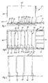
- Die Erfindung wird nachfolgend anhand von in der Zeichnung dargestellten Ausführungsbeispielen näher erläutert. Es zeigen:
- Fig. 1
- ein erstes Ausführungsbeispiel für einen Behälter mit den Erfindungsmerkmalen im Vertikalschnitt,
- Fig. 2
- den Behälter gemäß Fig. 1
- Fig. 3
- ein Schubelement für einen Behälter mit den Erfindungsmerkmalen,
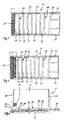
- Fig.4
- ein zweites Ausführungsbeispiel für einen Behälter mit den Erfindungsmerkmalen in Draufsicht,
- Fig.5
- ein drittes Ausführungsbeispiel für einen Behälter mit den Erfindungsmerkmalen in Draufsicht,
- Fig. 6
- den Behälter gemäß Fig. 5 im Vertikalschnitt,
- Fig. 7
- ein weiteres Ausführungsbeispiel für einen Behälter mit den Erfindungsmerkmalen im Vertikalschnitt.
- Die in den Fig. 1 bis 6 gezeigten Behälter sind sogenannte Schubbodenbunker 10. Sie können stationär zur Lagerung von Schüttgut, beispielsweise von Gartenabfällen, Hausabfällen oder Futtersilagen aus landwirtschaftlichen Betrieben, welche einem Fermenter oder einer Verbrennung dosiert zugeführt werden, eingesetzt werden oder auf (Anhänger-)Fahrgestellen als Transportbehälter dienen.
- Der Schubbodenbunker 10 weist eine Rückwand 11, eine Vorderwand 12, in der sich eine Ausschuböffnung 13 befindet, Seitenwände 14 und einen Boden 15 auf. Nach oben ist der Schubbodenbunker 10 zum Befüllen desselben offen, kann optional aber auch mit einem Deckel versehen sein.
- Auf dem Boden 15 sind zwei übereinander angeordnete Schubelemente 16, 17 angeordnet. Die Schubelemente 16, 17 sind in Richtung auf die Ausschuböffnung 13, also in Ausschubrichtung, und davon weg hin- und herbewegbar, wobei das untere Schubelement 17 auf dem Boden 15 und das obere Schubelement 16 auf dem unteren Schubelement 17 gleitet.
- In Fig. 3 ist das untere Schubelement 17 exemplarisch gezeigt. Es weist zwei zu beiden Seiten des Bodens 15 an den Seitenwänden 14 entlang verlaufende Schubstangen 18 auf, welche durch quer zur Ausschubrichtung verlaufende "Sprossen" 19 miteinander verbunden sind. Wie Fig. 2 zu entnehmen ist, gleiten die Sprossen 19 direkt über den Boden 15.
- Das obere Schubelement 16 ist analog zum unteren Schubelement 17 ausgebildet, nämlich ebenfalls mit Schubstangen 20 und Sprossen 21. Allerdings sind die Sprossen 21 hier über Stege 22 gegenüber den Schubstangen 20 nach unten versetzt, so daß diese in der selben Ebene wie die Sprossen 19 des unteren Schubelementes 17 angeordnet sind. Im vorliegenden Fall gleiten sie also ebenfalls über den Boden 15. Die Sprossen 19 und 21 sind, wie in Fig. 1 und 2 erkennbar, zwischeneinander und äquidistant zueinander angeordnet.
- Wie in Fig. 1 gut zu erkennen ist, sind die Sprossen 19, 21 im Querschnitt etwa dreieckig ausgebildet, nämlich mit von der Ausschuböffnung 13 weg abfallender Oberseite. Die etwa senkrechte Vorderseite bietet so beim Vorfahren der Schubelement 16, 17 einen guten Widerstand für das Schüttgut zum Ausschieben desselben. Beim Rückziehen der Schubelemente 16, 17 kann das Schüttgut aufgrund der abfallenden Oberseite gut über die Sprossen 19, 21 hinweggleiten, welche jetzt einen geringen Widerstand für das Schüttgut darstellen.
- Antriebe für die Schubelemente 16, 17 sind außerhalb des Schubbodenbunkers 10, nämlich hinter der Rückwand 11, vorgesehen. Die Schubstangen 18, 20 sind zu diesem Zweck durch Öffnungen in der Rückwand 11 hindurch nach außen geführt und werden über Druckmittelzylinder 23 hin- und hergehend angetrieben. Die Schubelemente 23 sind dabei mit je einem eigenen Antrieb ausgerüstet und können unabhängig voneinander angesteuert werden. Ein Bewegungszyklus läuft beispielsweise wie folgt ab:
- Zunächst werden beide Schubelemente 16 und 17 in Richtung auf die Ausschuböffnung 13 vorgefahren. Anschließend wird zunächst nur eines der beiden Schubelemente, beispielsweise das obere Schubelement 16 zurückgezogen, währen das andere Schubelement 17 noch ruht. Schließlich wird das andere Schubelement 17 zurückgezogen, während das erste Schubelement 16 ruht. Der Bewegungszyklus beginnt nun von neuem.
- Alternativ können die Schubelemente 16, 17 auch gemeinsam von der Ausschuböffnung 13 weg bewegt und dann zunächst eines der beiden Schubelemente 16, 17 während des Stillstandes des jeweils anderen Schubelementes 16, 17 in Richtung auf die Ausschuböffnung 13 zurückbewegt werden.
- Ferner können die oben beschriebenen Bewegungszyklen auch miteinander kombiniert werden oder auch frei, beispielsweise nach dem Zufallsprinzip, gesteuerte Bewegungszyklen vorgesehen sein.
- Bei sehr stark verfaserndem/verflochtenem Schüttgut können die Sprossen 19, 21 zusätzlich noch mit Messern (nicht dargestellt) ausgerüstet sein, deren Schneiden nach hinten auf die Rückwand weisen. Das Schüttgut wird dadurch beim Rückhub der Schubelemente 16, 17 zerschnitten, während die Messer beim Vorhub den Widerstand auf das Schüttgut noch vergrößern.
- Fig. 4 zeigt einen analogen Schubbodenbunker 10, bei dem vor der Ausschuböffnung 13 noch eine Schnecke 24 zum Abfördern des ausgeschobenen Schüttgutes angeordnet ist. Die Schnecke 24 fördert das Schüttgut zur Seite ab.
- Bei dem Ausführungsbeispiel gemäß Fig. 5 und 6 ist für sehr stark verfaserndes/verflochtenes Schüttgut noch eine Reiswalze 25 vorgesehen.
- Figur 7 zeigt eine auch unabhängig denkbare Weiterentwicklung der vorstehend beschriebenen Schubbodenbunker 10. Dieser Schubbodenbunker 10 weist einen Boden 15, Seitenwände 14, eine Rückwand 11 und eine Vorderwand 12 auf. Auf dem Boden 15 ist ein sogenannter und aus dem Stand der Technik bekannter Schubboden 16, 17 angeordnet, welcher durch hin- und herbewegen auf dem Boden 15 ein in den Schubbodenbunker 10 eingefülltes Schüttgut in Richtung auf die Vorderwand 12 austrägt. Der Schubboden 16, 17 ist dabei etwas kürzer bemessen, als der Boden 15. In einem freien Zwischenraum zwischen dem Schubboden 16, 17 und der Vorderwand 12 ist eine Förderschnecke 24 mit quer zur Förderrichtung des Schubbodens 16, 17 verlaufender Förderrichtung angeordnet. Das heißt, die Längsachse der Förderschnecke 24 ist quer zur Förderrichtung des Schubbodens 16, 17 angeordnet.
- Wie in Figur 7 gut zu erkennen ist, ist die Förderschnecke 24 vollständig oberhalb des Bodens 15 angeordnet. Mit anderen Worten, eine gedachte Mantelfläche 26 der Förderschnecke 24 unterschneidet den Boden 15 nicht. Vielmehr ist sie mit einem schmalen Spalt oberhalb des Bodens 15 angeordnet.
-
- 10
- Schubbodenbunker
- 11
- Rückwand
- 12
- Vorderwand
- 13
- Ausschuböffnung
- 14
- Seitenwand
- 15
- Boden
- 16
- Schubelement
- 17
- Schubelement
- 18
- Schubstange
- 19
- Sprosse
- 20
- Schubstange
- 21
- Sprosse
- 22
- Steg
- 23
- Druckmittelzylinder
- 24
- Schnecke
- 25
- Reiswalze
- 26
- Mantelfläche
Claims (10)
- Lager- und/oder Transportbehälter für Schüttgut, insbesondere Schubbodenbunker (10), mit einer Schubeinrichtung zum Ausschieben des Schüttgutes aus dem Behälter, welche wenigstens zwei in Ausschubrichtung sowie relativ zueinander hin- und herbewegbare Schubelemente (16, 17) aufweist, wobei jedem Schubelement (16, 17) ein eigener Antrieb (23) zugeordnet ist, dadurch gekennzeichnet, daß der Antrieb (23) eines der Schubelemente (16, 17) unabhängig vom Antrieb (23) eines der anderen Schubelemente (16, 17) ansteuerbar ist.
- Behälter nach Anspruch 1, dadurch gekennzeichnet, daß die Schubelemente (16, 17) aus dem Behälter herausgeführt sind und ein Antrieb (23) für die Schubelemente (16, 17) außerhalb des Behälters angeordnet ist.
- Behälter nach Anspruch 1 oder 2, dadurch gekennzeichnet, daß jedes Schubelement (16, 17) wenigstens eine Schubstange (18, 20), insbesondere zwei Schubstangen (18, 20) zu jeder Längsseite des Behälters, und quer zur Ausschubrichtung verlaufende Sprossen (19, 21) aufweist, welche versetzt zueinander angeordnet sind.
- Behälter nach einem der Ansprüche 1 bis 3, dadurch gekennzeichnet, daß die Schubelemente (16, 17) übereinander angeordnet sind, derart, daß das eine Schubelement (17) auf einem Behälterboden (14) aufliegt und das weitere Schubelement (16) um die Höhe des ersten Schubelementes (17) vom Behälterboden (14) beabstandet ist.
- Behälter nach einem der Ansprüche 1 bis 4, dadurch gekennzeichnet, daß die Sprossen (21) des einen Schubelementes (16) und die Sprossen (19) des weiteren Schubelementes (17) wenigstens über einen Bereich eines Bewegungszyklus relativ zueinander bewegt sind.
- Behälter nach einem der Ansprüche 1 bis 5, dadurch gekennzeichnet, daß wenigstens eines der Schubelemente (16, 17) mit Messern ausgerüstet ist, welche das Schüttgut bei Bewegung des Schubelementes (16, 17), insbesondere entgegen der Ausschubrichtung, schneiden.
- Behälter nach einem der Ansprüche 1 bis 6, dadurch gekennzeichnet, daß die Schubeinrichtung aus zwei oder mehr nebeneinander angeordneten Spalten von übereinander angeordneten Schubelementen gebildet ist.
- Lager- und/oder Transportbehälter für Schüttgut, insbesondere Schubbodenbunker (10), mit einem Boden (15), einer ersten, auf dem Boden (15) angeordneten Austrageinrichtung, vorzugsweise einem Schubboden (16, 17), für das Schüttgut und einer weiteren Austrageinrichtung mit quer zur ersten Austrageinrichtung verlaufender Förderrichtung, insbesondere nach einem der Ansprüche 1 bis 7, dadurch gekennzeichnet, daß die weitere Austrageinrichtung zumindest teilweise oberhalb des Bodens (11) angeordnet ist.
- Behälter nach Anspruch 8, dadurch gekennzeichnet, daß die weitere Austrageinrichtung eine Förderschnecke (24) ist, insbesondere mit einer oberhalb des Bodens (15) angeordneten Längsachse, vorzugsweise derart, daß eine gedachte Mantelfläche (26) der Förderschnecke (24) den Boden (15) nicht unterschneidet.
- Verfahren zum Ausschieben von Schüttgut aus einem Behälter (10) mit wenigstens zwei in Ausschubrichtung hin- und herbeweglichen Schubelementen (16, 17), dadurch gekennzeichnet, daß das jeweils eine Schubelement (16, 17) auch während einer Stillstandsphase des jeweils anderen Schubelementes (16, 17 bewegbar ist, insbesondere indem die Schubelemente (16, 17) gemeinsam in Richtung auf eine Entnahmeöffnung (13) oder von ihr weg bewegt, sodann zunächst das eine Schubelement (16) während eines Stillstandes des weiteren Schubelementes (17) von der Entnahmeöffnung weg oder zu ihr hin (zurück-)bewegt und schließlich das weitere Schubelement (17) während des Stillstandes des ersten Schubelementes (16) zurückbewegt wird.
Priority Applications (1)
| Application Number | Priority Date | Filing Date | Title |
|---|---|---|---|
| PL05107649T PL1627832T3 (pl) | 2004-08-20 | 2005-08-19 | Zbiornik na materiał masowy z urządzeniem popychającym |
Applications Claiming Priority (2)
| Application Number | Priority Date | Filing Date | Title |
|---|---|---|---|
| DE200410040731 DE102004040731B4 (de) | 2004-08-20 | 2004-08-20 | Lager- und/oder Transportbehälter |
| DE200410054651 DE102004054651A1 (de) | 2004-11-11 | 2004-11-11 | Lager- und/oder Transportbehälter für Schüttgut, insbesondere Schubbodenbunker |
Publications (2)
| Publication Number | Publication Date |
|---|---|
| EP1627832A1 true EP1627832A1 (de) | 2006-02-22 |
| EP1627832B1 EP1627832B1 (de) | 2011-03-30 |
Family
ID=35385813
Family Applications (1)
| Application Number | Title | Priority Date | Filing Date |
|---|---|---|---|
| EP05107649A Expired - Lifetime EP1627832B1 (de) | 2004-08-20 | 2005-08-19 | Behälter für Schüttgut mit einer Schubeinrichtung |
Country Status (4)
| Country | Link |
|---|---|
| EP (1) | EP1627832B1 (de) |
| AT (1) | ATE503710T1 (de) |
| DE (1) | DE502005011183D1 (de) |
| PL (1) | PL1627832T3 (de) |
Cited By (5)
| Publication number | Priority date | Publication date | Assignee | Title |
|---|---|---|---|---|
| AT503945B1 (de) * | 2006-11-03 | 2008-02-15 | Maraton Energietechnik Gmbh | Vorrichtung zum austragen von organischem schüttgut |
| EP1970435A1 (de) | 2007-03-13 | 2008-09-17 | MARATON Energie Technik GmbH | Vorrichtung zur Gärgutbeschickung einer Gäranlage |
| CN100588594C (zh) * | 2008-04-14 | 2010-02-10 | 河北省农林科学院旱作农业研究所 | 保持土体构造的地块迁移装置及用其进行地块迁移的方法 |
| CN105501737A (zh) * | 2016-01-18 | 2016-04-20 | 烟台博海木工机械有限公司 | 一种活底料仓 |
| CN117262648A (zh) * | 2023-10-13 | 2023-12-22 | 南通四通林业机械制造安装有限公司 | 一种具有辅助结构的输送装置 |
Citations (6)
| Publication number | Priority date | Publication date | Assignee | Title |
|---|---|---|---|---|
| US3923149A (en) * | 1973-06-08 | 1975-12-02 | Mill Supply Inc | Material handling apparatus for hogged fuel |
| US4363586A (en) * | 1978-11-13 | 1982-12-14 | Schwabische Huttenwerke Gesellschaft Mit Beschrankter Haftung | Bunker-discharge apparatus, especially for bulk material |
| US4461606A (en) * | 1981-06-02 | 1984-07-24 | S.W. Hooper & Co. Ltd. | Supporting grip for bin or hopper |
| DE4008287A1 (de) | 1990-03-15 | 1991-09-19 | Rompf Klaerwerkeinrichtungen G | Aufbewahrungsbehaelter |
| CH688892A5 (de) * | 1994-08-24 | 1998-05-15 | Hinsen Hermann | Vorrichtung zum Verschieben mindestens eines Teils einer Aufschuettung von Schuettgut. |
| US6513648B1 (en) * | 2000-11-06 | 2003-02-04 | Olof A. Hallstrom | Reciprocating conveyor with top front drive |
-
2005
- 2005-08-19 AT AT05107649T patent/ATE503710T1/de active
- 2005-08-19 EP EP05107649A patent/EP1627832B1/de not_active Expired - Lifetime
- 2005-08-19 DE DE502005011183T patent/DE502005011183D1/de not_active Expired - Lifetime
- 2005-08-19 PL PL05107649T patent/PL1627832T3/pl unknown
Patent Citations (6)
| Publication number | Priority date | Publication date | Assignee | Title |
|---|---|---|---|---|
| US3923149A (en) * | 1973-06-08 | 1975-12-02 | Mill Supply Inc | Material handling apparatus for hogged fuel |
| US4363586A (en) * | 1978-11-13 | 1982-12-14 | Schwabische Huttenwerke Gesellschaft Mit Beschrankter Haftung | Bunker-discharge apparatus, especially for bulk material |
| US4461606A (en) * | 1981-06-02 | 1984-07-24 | S.W. Hooper & Co. Ltd. | Supporting grip for bin or hopper |
| DE4008287A1 (de) | 1990-03-15 | 1991-09-19 | Rompf Klaerwerkeinrichtungen G | Aufbewahrungsbehaelter |
| CH688892A5 (de) * | 1994-08-24 | 1998-05-15 | Hinsen Hermann | Vorrichtung zum Verschieben mindestens eines Teils einer Aufschuettung von Schuettgut. |
| US6513648B1 (en) * | 2000-11-06 | 2003-02-04 | Olof A. Hallstrom | Reciprocating conveyor with top front drive |
Cited By (5)
| Publication number | Priority date | Publication date | Assignee | Title |
|---|---|---|---|---|
| AT503945B1 (de) * | 2006-11-03 | 2008-02-15 | Maraton Energietechnik Gmbh | Vorrichtung zum austragen von organischem schüttgut |
| EP1970435A1 (de) | 2007-03-13 | 2008-09-17 | MARATON Energie Technik GmbH | Vorrichtung zur Gärgutbeschickung einer Gäranlage |
| CN100588594C (zh) * | 2008-04-14 | 2010-02-10 | 河北省农林科学院旱作农业研究所 | 保持土体构造的地块迁移装置及用其进行地块迁移的方法 |
| CN105501737A (zh) * | 2016-01-18 | 2016-04-20 | 烟台博海木工机械有限公司 | 一种活底料仓 |
| CN117262648A (zh) * | 2023-10-13 | 2023-12-22 | 南通四通林业机械制造安装有限公司 | 一种具有辅助结构的输送装置 |
Also Published As
| Publication number | Publication date |
|---|---|
| ATE503710T1 (de) | 2011-04-15 |
| PL1627832T3 (pl) | 2011-09-30 |
| EP1627832B1 (de) | 2011-03-30 |
| DE502005011183D1 (de) | 2011-05-12 |
Similar Documents
| Publication | Publication Date | Title |
|---|---|---|
| DE69427224T2 (de) | Ballenmaschine | |
| DE1556516C3 (de) | Vorrichtung zum kontinuierlichen oder diskontinuierlichen Beladen des Ladebehälters eines Müllfahrzeuges | |
| EP2658707B1 (de) | Förder- und/oder presseinrichtung mit einer vorgeschalteten zuführeinrichtung | |
| EP3354601A1 (de) | Bunker mit hin- und hergehendem förderer | |
| DE102004040731B4 (de) | Lager- und/oder Transportbehälter | |
| DE2701336C2 (de) | Bunkerverschluß | |
| EP4005389A1 (de) | Querverteilvorrichtung | |
| DE69822022T2 (de) | Förderer mit hin- und herbewegten Rohren | |
| EP3017939A1 (de) | Ballenpresse | |
| EP1627832B1 (de) | Behälter für Schüttgut mit einer Schubeinrichtung | |
| EP2289824B1 (de) | Beschicker für Biomasse | |
| DE2400547C3 (de) | Bunker mit Austragvorrichtung | |
| WO1994023558A2 (de) | Verfahren und presse zum bilden quaderförmiger pressballen aus landwirtschaftlichem erntegut | |
| EP2578518B1 (de) | Fördereinrichtung zum Transport von Schüttgut | |
| AT413314B (de) | Ballenauflöser | |
| DE102017119092B4 (de) | Kasten-Ballenpresse mit Schiebetür sowie Verfahren zum Betreiben einer solchen Kastenpresse. | |
| DE20201339U1 (de) | Futtermischer | |
| DE4014462A1 (de) | Vorrichtung zum auflockern von schuettgut | |
| DE3410301C2 (de) | Silo für Schüttgut | |
| WO2006061198A1 (de) | Vorrichtung und verfahren zum schonenden abfüllen eines stückige anteile enthaltenden produkts in behälter | |
| DE10206686B4 (de) | Schüttgutlagerung mit Obenentnahme | |
| CH688892A5 (de) | Vorrichtung zum Verschieben mindestens eines Teils einer Aufschuettung von Schuettgut. | |
| DE202008009771U1 (de) | Lager- und Transportbehälter | |
| AT503945B1 (de) | Vorrichtung zum austragen von organischem schüttgut | |
| DE3142491C2 (de) | Ladewagen |
Legal Events
| Date | Code | Title | Description |
|---|---|---|---|
| PUAI | Public reference made under article 153(3) epc to a published international application that has entered the european phase |
Free format text: ORIGINAL CODE: 0009012 |
|
| AK | Designated contracting states |
Kind code of ref document: A1 Designated state(s): AT BE BG CH CY CZ DE DK EE ES FI FR GB GR HU IE IS IT LI LT LU LV MC NL PL PT RO SE SI SK TR |
|
| AX | Request for extension of the european patent |
Extension state: AL BA HR MK YU |
|
| 17P | Request for examination filed |
Effective date: 20060822 |
|
| 17Q | First examination report despatched |
Effective date: 20060925 |
|
| AKX | Designation fees paid |
Designated state(s): AT BE BG CH CY CZ DE DK EE ES FI FR GB GR HU IE IS IT LI LT LU LV MC NL PL PT RO SE SI SK TR |
|
| GRAP | Despatch of communication of intention to grant a patent |
Free format text: ORIGINAL CODE: EPIDOSNIGR1 |
|
| GRAS | Grant fee paid |
Free format text: ORIGINAL CODE: EPIDOSNIGR3 |
|
| GRAJ | Information related to disapproval of communication of intention to grant by the applicant or resumption of examination proceedings by the epo deleted |
Free format text: ORIGINAL CODE: EPIDOSDIGR1 |
|
| GRAP | Despatch of communication of intention to grant a patent |
Free format text: ORIGINAL CODE: EPIDOSNIGR1 |
|
| RAP1 | Party data changed (applicant data changed or rights of an application transferred) |
Owner name: MT-ENERGIE GMBH & CO. KG |
|
| GRAS | Grant fee paid |
Free format text: ORIGINAL CODE: EPIDOSNIGR3 |
|
| RAP1 | Party data changed (applicant data changed or rights of an application transferred) |
Owner name: MT-ENERGIE GMBH |
|
| GRAA | (expected) grant |
Free format text: ORIGINAL CODE: 0009210 |
|
| AK | Designated contracting states |
Kind code of ref document: B1 Designated state(s): AT BE BG CH CY CZ DE DK EE ES FI FR GB GR HU IE IS IT LI LT LU LV MC NL PL PT RO SE SI SK TR |
|
| REG | Reference to a national code |
Ref country code: GB Ref legal event code: FG4D Free format text: NOT ENGLISH |
|
| REG | Reference to a national code |
Ref country code: CH Ref legal event code: EP |
|
| REG | Reference to a national code |
Ref country code: IE Ref legal event code: FG4D |
|
| REF | Corresponds to: |
Ref document number: 502005011183 Country of ref document: DE Date of ref document: 20110512 Kind code of ref document: P |
|
| REG | Reference to a national code |
Ref country code: DE Ref legal event code: R096 Ref document number: 502005011183 Country of ref document: DE Effective date: 20110512 |
|
| REG | Reference to a national code |
Ref country code: NL Ref legal event code: VDEP Effective date: 20110330 |
|
| PG25 | Lapsed in a contracting state [announced via postgrant information from national office to epo] |
Ref country code: SE Free format text: LAPSE BECAUSE OF FAILURE TO SUBMIT A TRANSLATION OF THE DESCRIPTION OR TO PAY THE FEE WITHIN THE PRESCRIBED TIME-LIMIT Effective date: 20110330 Ref country code: LT Free format text: LAPSE BECAUSE OF FAILURE TO SUBMIT A TRANSLATION OF THE DESCRIPTION OR TO PAY THE FEE WITHIN THE PRESCRIBED TIME-LIMIT Effective date: 20110330 Ref country code: LV Free format text: LAPSE BECAUSE OF FAILURE TO SUBMIT A TRANSLATION OF THE DESCRIPTION OR TO PAY THE FEE WITHIN THE PRESCRIBED TIME-LIMIT Effective date: 20110330 Ref country code: GR Free format text: LAPSE BECAUSE OF FAILURE TO SUBMIT A TRANSLATION OF THE DESCRIPTION OR TO PAY THE FEE WITHIN THE PRESCRIBED TIME-LIMIT Effective date: 20110701 |
|
| LTIE | Lt: invalidation of european patent or patent extension |
Effective date: 20110330 |
|
| PG25 | Lapsed in a contracting state [announced via postgrant information from national office to epo] |
Ref country code: SI Free format text: LAPSE BECAUSE OF FAILURE TO SUBMIT A TRANSLATION OF THE DESCRIPTION OR TO PAY THE FEE WITHIN THE PRESCRIBED TIME-LIMIT Effective date: 20110330 Ref country code: FI Free format text: LAPSE BECAUSE OF FAILURE TO SUBMIT A TRANSLATION OF THE DESCRIPTION OR TO PAY THE FEE WITHIN THE PRESCRIBED TIME-LIMIT Effective date: 20110330 Ref country code: CY Free format text: LAPSE BECAUSE OF FAILURE TO SUBMIT A TRANSLATION OF THE DESCRIPTION OR TO PAY THE FEE WITHIN THE PRESCRIBED TIME-LIMIT Effective date: 20110330 |
|
| REG | Reference to a national code |
Ref country code: PL Ref legal event code: T3 |
|
| REG | Reference to a national code |
Ref country code: SK Ref legal event code: T3 Ref document number: E 9680 Country of ref document: SK |
|
| REG | Reference to a national code |
Ref country code: IE Ref legal event code: FD4D |
|
| PG25 | Lapsed in a contracting state [announced via postgrant information from national office to epo] |
Ref country code: EE Free format text: LAPSE BECAUSE OF FAILURE TO SUBMIT A TRANSLATION OF THE DESCRIPTION OR TO PAY THE FEE WITHIN THE PRESCRIBED TIME-LIMIT Effective date: 20110330 Ref country code: PT Free format text: LAPSE BECAUSE OF FAILURE TO SUBMIT A TRANSLATION OF THE DESCRIPTION OR TO PAY THE FEE WITHIN THE PRESCRIBED TIME-LIMIT Effective date: 20110801 |
|
| PG25 | Lapsed in a contracting state [announced via postgrant information from national office to epo] |
Ref country code: RO Free format text: LAPSE BECAUSE OF FAILURE TO SUBMIT A TRANSLATION OF THE DESCRIPTION OR TO PAY THE FEE WITHIN THE PRESCRIBED TIME-LIMIT Effective date: 20110330 Ref country code: IS Free format text: LAPSE BECAUSE OF FAILURE TO SUBMIT A TRANSLATION OF THE DESCRIPTION OR TO PAY THE FEE WITHIN THE PRESCRIBED TIME-LIMIT Effective date: 20110730 Ref country code: ES Free format text: LAPSE BECAUSE OF FAILURE TO SUBMIT A TRANSLATION OF THE DESCRIPTION OR TO PAY THE FEE WITHIN THE PRESCRIBED TIME-LIMIT Effective date: 20110711 |
|
| PG25 | Lapsed in a contracting state [announced via postgrant information from national office to epo] |
Ref country code: NL Free format text: LAPSE BECAUSE OF FAILURE TO SUBMIT A TRANSLATION OF THE DESCRIPTION OR TO PAY THE FEE WITHIN THE PRESCRIBED TIME-LIMIT Effective date: 20110330 |
|
| PG25 | Lapsed in a contracting state [announced via postgrant information from national office to epo] |
Ref country code: IE Free format text: LAPSE BECAUSE OF FAILURE TO SUBMIT A TRANSLATION OF THE DESCRIPTION OR TO PAY THE FEE WITHIN THE PRESCRIBED TIME-LIMIT Effective date: 20110330 |
|
| PLBE | No opposition filed within time limit |
Free format text: ORIGINAL CODE: 0009261 |
|
| STAA | Information on the status of an ep patent application or granted ep patent |
Free format text: STATUS: NO OPPOSITION FILED WITHIN TIME LIMIT |
|
| BERE | Be: lapsed |
Owner name: MT-ENERGIE G.M.B.H. Effective date: 20110831 |
|
| PG25 | Lapsed in a contracting state [announced via postgrant information from national office to epo] |
Ref country code: DK Free format text: LAPSE BECAUSE OF FAILURE TO SUBMIT A TRANSLATION OF THE DESCRIPTION OR TO PAY THE FEE WITHIN THE PRESCRIBED TIME-LIMIT Effective date: 20110330 |
|
| 26N | No opposition filed |
Effective date: 20120102 |
|
| PG25 | Lapsed in a contracting state [announced via postgrant information from national office to epo] |
Ref country code: MC Free format text: LAPSE BECAUSE OF NON-PAYMENT OF DUE FEES Effective date: 20110831 |
|
| REG | Reference to a national code |
Ref country code: CH Ref legal event code: PL |
|
| REG | Reference to a national code |
Ref country code: DE Ref legal event code: R097 Ref document number: 502005011183 Country of ref document: DE Effective date: 20120102 |
|
| PG25 | Lapsed in a contracting state [announced via postgrant information from national office to epo] |
Ref country code: CH Free format text: LAPSE BECAUSE OF NON-PAYMENT OF DUE FEES Effective date: 20110831 Ref country code: LI Free format text: LAPSE BECAUSE OF NON-PAYMENT OF DUE FEES Effective date: 20110831 |
|
| PG25 | Lapsed in a contracting state [announced via postgrant information from national office to epo] |
Ref country code: BE Free format text: LAPSE BECAUSE OF NON-PAYMENT OF DUE FEES Effective date: 20110831 |
|
| REG | Reference to a national code |
Ref country code: AT Ref legal event code: MM01 Ref document number: 503710 Country of ref document: AT Kind code of ref document: T Effective date: 20110819 |
|
| PG25 | Lapsed in a contracting state [announced via postgrant information from national office to epo] |
Ref country code: AT Free format text: LAPSE BECAUSE OF NON-PAYMENT OF DUE FEES Effective date: 20110819 |
|
| PG25 | Lapsed in a contracting state [announced via postgrant information from national office to epo] |
Ref country code: LU Free format text: LAPSE BECAUSE OF NON-PAYMENT OF DUE FEES Effective date: 20110819 |
|
| PG25 | Lapsed in a contracting state [announced via postgrant information from national office to epo] |
Ref country code: BG Free format text: LAPSE BECAUSE OF FAILURE TO SUBMIT A TRANSLATION OF THE DESCRIPTION OR TO PAY THE FEE WITHIN THE PRESCRIBED TIME-LIMIT Effective date: 20110630 |
|
| PG25 | Lapsed in a contracting state [announced via postgrant information from national office to epo] |
Ref country code: TR Free format text: LAPSE BECAUSE OF FAILURE TO SUBMIT A TRANSLATION OF THE DESCRIPTION OR TO PAY THE FEE WITHIN THE PRESCRIBED TIME-LIMIT Effective date: 20110330 |
|
| PG25 | Lapsed in a contracting state [announced via postgrant information from national office to epo] |
Ref country code: HU Free format text: LAPSE BECAUSE OF FAILURE TO SUBMIT A TRANSLATION OF THE DESCRIPTION OR TO PAY THE FEE WITHIN THE PRESCRIBED TIME-LIMIT Effective date: 20110330 |
|
| PGFP | Annual fee paid to national office [announced via postgrant information from national office to epo] |
Ref country code: CZ Payment date: 20140711 Year of fee payment: 10 |
|
| PGFP | Annual fee paid to national office [announced via postgrant information from national office to epo] |
Ref country code: SK Payment date: 20140818 Year of fee payment: 10 Ref country code: PL Payment date: 20140714 Year of fee payment: 10 |
|
| REG | Reference to a national code |
Ref country code: DE Ref legal event code: R082 Ref document number: 502005011183 Country of ref document: DE Representative=s name: KUHNEN & WACKER PATENT- UND RECHTSANWALTSBUERO, DE |
|
| REG | Reference to a national code |
Ref country code: DE Ref legal event code: R081 Ref document number: 502005011183 Country of ref document: DE Owner name: MT-ENERGIE SERVICE GMBH, DE Free format text: FORMER OWNER: MT-ENERGIE GMBH & CO. KG, 27404 OSTEREISTEDT, DE Effective date: 20110303 Ref country code: DE Ref legal event code: R081 Ref document number: 502005011183 Country of ref document: DE Owner name: MT-ENERGIE SERVICE GMBH, DE Free format text: FORMER OWNER: MT-ENERGIE GMBH, 27404 ZEVEN, DE Effective date: 20150505 Ref country code: DE Ref legal event code: R082 Ref document number: 502005011183 Country of ref document: DE Representative=s name: KUHNEN & WACKER PATENT- UND RECHTSANWALTSBUERO, DE Effective date: 20150505 |
|
| REG | Reference to a national code |
Ref country code: FR Ref legal event code: PLFP Year of fee payment: 11 |
|
| PG25 | Lapsed in a contracting state [announced via postgrant information from national office to epo] |
Ref country code: CZ Free format text: LAPSE BECAUSE OF NON-PAYMENT OF DUE FEES Effective date: 20150819 Ref country code: SK Free format text: LAPSE BECAUSE OF NON-PAYMENT OF DUE FEES Effective date: 20150819 |
|
| REG | Reference to a national code |
Ref country code: SK Ref legal event code: MM4A Ref document number: E 9680 Country of ref document: SK Effective date: 20150819 |
|
| REG | Reference to a national code |
Ref country code: FR Ref legal event code: PLFP Year of fee payment: 12 |
|
| PG25 | Lapsed in a contracting state [announced via postgrant information from national office to epo] |
Ref country code: PL Free format text: LAPSE BECAUSE OF NON-PAYMENT OF DUE FEES Effective date: 20150819 |
|
| REG | Reference to a national code |
Ref country code: FR Ref legal event code: PLFP Year of fee payment: 13 |
|
| REG | Reference to a national code |
Ref country code: FR Ref legal event code: PLFP Year of fee payment: 14 |
|
| PGFP | Annual fee paid to national office [announced via postgrant information from national office to epo] |
Ref country code: FR Payment date: 20200813 Year of fee payment: 16 Ref country code: GB Payment date: 20200812 Year of fee payment: 16 |
|
| PGFP | Annual fee paid to national office [announced via postgrant information from national office to epo] |
Ref country code: IT Payment date: 20200812 Year of fee payment: 16 |
|
| GBPC | Gb: european patent ceased through non-payment of renewal fee |
Effective date: 20210819 |
|
| PG25 | Lapsed in a contracting state [announced via postgrant information from national office to epo] |
Ref country code: IT Free format text: LAPSE BECAUSE OF NON-PAYMENT OF DUE FEES Effective date: 20210819 Ref country code: GB Free format text: LAPSE BECAUSE OF NON-PAYMENT OF DUE FEES Effective date: 20210819 Ref country code: FR Free format text: LAPSE BECAUSE OF NON-PAYMENT OF DUE FEES Effective date: 20210831 |
|
| PGFP | Annual fee paid to national office [announced via postgrant information from national office to epo] |
Ref country code: DE Payment date: 20220620 Year of fee payment: 18 |
|
| REG | Reference to a national code |
Ref country code: DE Ref legal event code: R119 Ref document number: 502005011183 Country of ref document: DE |
|
| PG25 | Lapsed in a contracting state [announced via postgrant information from national office to epo] |
Ref country code: DE Free format text: LAPSE BECAUSE OF NON-PAYMENT OF DUE FEES Effective date: 20240301 |