EP1628017A2 - Regelventil für einen Kompressor mit veränderlicher Verdrängung - Google Patents
Regelventil für einen Kompressor mit veränderlicher Verdrängung Download PDFInfo
- Publication number
- EP1628017A2 EP1628017A2 EP05017519A EP05017519A EP1628017A2 EP 1628017 A2 EP1628017 A2 EP 1628017A2 EP 05017519 A EP05017519 A EP 05017519A EP 05017519 A EP05017519 A EP 05017519A EP 1628017 A2 EP1628017 A2 EP 1628017A2
- Authority
- EP
- European Patent Office
- Prior art keywords
- pressure
- valve
- crank
- effective
- receiving area
- Prior art date
- Legal status (The legal status is an assumption and is not a legal conclusion. Google has not performed a legal analysis and makes no representation as to the accuracy of the status listed.)
- Withdrawn
Links
Images
Classifications
-
- F—MECHANICAL ENGINEERING; LIGHTING; HEATING; WEAPONS; BLASTING
- F04—POSITIVE - DISPLACEMENT MACHINES FOR LIQUIDS; PUMPS FOR LIQUIDS OR ELASTIC FLUIDS
- F04B—POSITIVE-DISPLACEMENT MACHINES FOR LIQUIDS; PUMPS
- F04B27/00—Multi-cylinder pumps specially adapted for elastic fluids and characterised by number or arrangement of cylinders
- F04B27/08—Multi-cylinder pumps specially adapted for elastic fluids and characterised by number or arrangement of cylinders having cylinders coaxial with, or parallel or inclined to, main shaft axis
- F04B27/14—Control
- F04B27/16—Control of pumps with stationary cylinders
- F04B27/18—Control of pumps with stationary cylinders by varying the relative positions of a swash plate and a cylinder block
- F04B27/1804—Controlled by crankcase pressure
-
- F—MECHANICAL ENGINEERING; LIGHTING; HEATING; WEAPONS; BLASTING
- F04—POSITIVE - DISPLACEMENT MACHINES FOR LIQUIDS; PUMPS FOR LIQUIDS OR ELASTIC FLUIDS
- F04B—POSITIVE-DISPLACEMENT MACHINES FOR LIQUIDS; PUMPS
- F04B27/00—Multi-cylinder pumps specially adapted for elastic fluids and characterised by number or arrangement of cylinders
- F04B27/08—Multi-cylinder pumps specially adapted for elastic fluids and characterised by number or arrangement of cylinders having cylinders coaxial with, or parallel or inclined to, main shaft axis
- F04B27/14—Control
-
- F—MECHANICAL ENGINEERING; LIGHTING; HEATING; WEAPONS; BLASTING
- F04—POSITIVE - DISPLACEMENT MACHINES FOR LIQUIDS; PUMPS FOR LIQUIDS OR ELASTIC FLUIDS
- F04B—POSITIVE-DISPLACEMENT MACHINES FOR LIQUIDS; PUMPS
- F04B39/00—Component parts, details, or accessories, of pumps or pumping systems specially adapted for elastic fluids, not otherwise provided for in, or of interest apart from, groups F04B25/00 - F04B37/00
- F04B39/10—Adaptations or arrangements of distribution members
-
- F—MECHANICAL ENGINEERING; LIGHTING; HEATING; WEAPONS; BLASTING
- F04—POSITIVE - DISPLACEMENT MACHINES FOR LIQUIDS; PUMPS FOR LIQUIDS OR ELASTIC FLUIDS
- F04B—POSITIVE-DISPLACEMENT MACHINES FOR LIQUIDS; PUMPS
- F04B27/00—Multi-cylinder pumps specially adapted for elastic fluids and characterised by number or arrangement of cylinders
- F04B27/08—Multi-cylinder pumps specially adapted for elastic fluids and characterised by number or arrangement of cylinders having cylinders coaxial with, or parallel or inclined to, main shaft axis
- F04B27/14—Control
- F04B27/16—Control of pumps with stationary cylinders
- F04B27/18—Control of pumps with stationary cylinders by varying the relative positions of a swash plate and a cylinder block
- F04B27/1804—Controlled by crankcase pressure
- F04B2027/1822—Valve-controlled fluid connection
- F04B2027/1827—Valve-controlled fluid connection between crankcase and discharge chamber
-
- F—MECHANICAL ENGINEERING; LIGHTING; HEATING; WEAPONS; BLASTING
- F04—POSITIVE - DISPLACEMENT MACHINES FOR LIQUIDS; PUMPS FOR LIQUIDS OR ELASTIC FLUIDS
- F04B—POSITIVE-DISPLACEMENT MACHINES FOR LIQUIDS; PUMPS
- F04B27/00—Multi-cylinder pumps specially adapted for elastic fluids and characterised by number or arrangement of cylinders
- F04B27/08—Multi-cylinder pumps specially adapted for elastic fluids and characterised by number or arrangement of cylinders having cylinders coaxial with, or parallel or inclined to, main shaft axis
- F04B27/14—Control
- F04B27/16—Control of pumps with stationary cylinders
- F04B27/18—Control of pumps with stationary cylinders by varying the relative positions of a swash plate and a cylinder block
- F04B27/1804—Controlled by crankcase pressure
- F04B2027/184—Valve controlling parameter
- F04B2027/1854—External parameters
-
- F—MECHANICAL ENGINEERING; LIGHTING; HEATING; WEAPONS; BLASTING
- F04—POSITIVE - DISPLACEMENT MACHINES FOR LIQUIDS; PUMPS FOR LIQUIDS OR ELASTIC FLUIDS
- F04B—POSITIVE-DISPLACEMENT MACHINES FOR LIQUIDS; PUMPS
- F04B27/00—Multi-cylinder pumps specially adapted for elastic fluids and characterised by number or arrangement of cylinders
- F04B27/08—Multi-cylinder pumps specially adapted for elastic fluids and characterised by number or arrangement of cylinders having cylinders coaxial with, or parallel or inclined to, main shaft axis
- F04B27/14—Control
- F04B27/16—Control of pumps with stationary cylinders
- F04B27/18—Control of pumps with stationary cylinders by varying the relative positions of a swash plate and a cylinder block
- F04B27/1804—Controlled by crankcase pressure
- F04B2027/184—Valve controlling parameter
- F04B2027/1859—Suction pressure
Definitions
- the invention relates to a control valve according to the preamble of claim 1, particularly for controlling the compressor discharge capacity in an automotive air conditioner.
- Variable displacement compressors in automotive air conditioners capable of changing the refrigerant discharge capacity are generally employed so as to obtain an adequate refrigerating capacity without being constrained by the rotational speed of an engine driving the compressor.
- a swash plate driven by the engine via a shaft for performing a wobbling motion is disposed within a crankcase such that the inclination angle of the swash plate can be changed.
- Pistons are reciprocatingly driven by the swash plate draw in order to refrigerant from a suction chamber into cylinders, to compress and to discharge compressed refrigerant into a discharge chamber.
- the inclination angle changing the discharge capacity is varied by changing the pressure in the crankcase.
- a control valve controls the pressure in the crankcase.
- a known control valve decompresses refrigerant at discharge pressure Pd to introduce the decompressed refrigerant into the crankcase, and controls the pressure Pc (crankcase pressure) by controlling the amount of introduced refrigerant.
- External electric current is supplied to a solenoid of the control valve for the actuation of a valve element, specifically, by a method based on the value of a suction pressure Ps in the suction chamber, for example.
- the control valve senses the suction pressure Ps, and controls the flow rate into the crankcase such that the suction pressure Ps is maintained at a predetermined level.
- the value of suction pressure Ps at which the variable displacement operation is to be started can be freely set by the electric current. However, it then is necessary to provide a movable flexible member, such as a diaphragm or a bellows, for sensing the suction pressure Ps, which undesirably increases the dimension of the control valve.
- a valve section performs an opening/closing operation initiated by the differential pressure (Pd ⁇ Ps), irrespective of the crankcase pressure Pc.
- the discharge pressure Pd and the suction pressure Ps directly load the valve element for sensing the differential pressure, and hence it is possible to dispense with the above-mentioned flexible member.
- the discharge pressure Pd is directly sensed, it is possible to truly reflect any change in pressure of the variable displacement compressor, and hence to obtain a displacement control with excellent response.
- the crankcase pressure Pc is increased by increasing the value of the differential pressure (Pd ⁇ Ps), and conversely the value of the differential pressure (Pd - Ps) as well is varied to some extent by variations in the crankcase pressure Pc, etc.
- the value of the differential pressure (Pd ⁇ Ps) increases as well with a slight slope or ramp characteristic, for example.
- this phenomenon may not be ideal when considering only the characteristics of the control valve, this is not always true when considering matching between "the Pd-Ps differential pressure control" performed by the control valve and the control of the variable displacement compressor itself.
- the differential pressure (Pd ⁇ Ps) instantaneously rises to a fixed value in response to a change in the value of electric current supplied to the solenoid, the valve section instantaneously will open, which enhances the response of the swash plate but nevertheless sometimes causes hunting or overshooting in the displacement control. This makes it difficult to stably perform the displacement control.
- the degree (slope) of the influence of the crankcase pressure Pc on a change in the differential pressure (Pd ⁇ Ps) has conventionally been adjusted e.g. by changing the characteristic of a spring which urges the valve element in one moving direction, or by changing the attractive force characteristic of the solenoid according to characteristics required of the control valve.
- the characteristic of the spring or the attractive force characteristic of the solenoid is changed, the differential pressure characteristics, i.e. the relationship between the value of the electric current and the value of the differential pressure (Pd ⁇ Ps) may also change, which makes it difficult to perform a total tuning operation.
- the plunger is made to move in unison with the valve element via the shaft
- the plunger does not necessarily mean that the plunger needs to directly co-act with the shaft, but it even may co-act with the shaft via an interposed object formed separately from the shaft.
- the effective pressure-receiving area on the discharge pressure side of the intermediate structure and the effective pressure-receiving area on the suction pressure side of the intermediate structure which are originally set equal to each other are intentionally configured such that the balance therebetween is lost.
- the differential pressure • crank pressure characteristics characteristics concerning the degree of the influence of the crank pressure on a change in the differential pressure
- the effective pressure-receiving areas even may be equal in a boundary condition depending on the characteristics to be obtained.
- Desired “differential pressure • crank pressure characteristics” can be obtained by adjusting the difference between the effective pressure-receiving area on the discharge pressure side of the intermediate structure formed by making the valve element and the shaft move in unison with each other, and the effective pressure-receiving area on the suction pressure side of the intermediate structure. Since the changes in the effective pressure-receiving areas have almost no influence on “the electric current • differential pressure characteristics", it is possible to obtain desired “differential pressure • crank pressure characteristics" with ease.
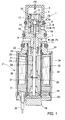
- the control valve in Fig. 1 introduces flow rate controlled discharge refrigerant of a variable displacement compressor (not shown into the crankcase.
- the control valve integrally comprises a valve-forming section 1 containing a valve section, and a solenoid 2 for controlling the valve lift.
- An open upper end of a stepped hollow cylindrical upper body defines a discharge pressure port 4 communicating with the compressor discharge chamber (discharge pressure Pd).
- a strainer 5 is capped on the upper body 3.
- the discharge pressure port 4 communicates with a crankcase pressure port 6 in a side of a central portion of the upper body 3.
- the crank pressure port 6 communicates with the crankcase (crank pressure).
- a suction pressure port 7 in a side of a lower portion of the upper body 3 communicates with the suction chamber (suction pressure Ps).
- a refrigerant passage 7a connected to the suction pressure port 7 changes direction downward inside the upper body 3.
- crankcase-communicating chamber 8 (crank pressure Pc) is formed between the ports 4, 6.
- An axially extending guide hole 9 in the centre of the lower portion of the upper body 3 axially guides a shaft 18.
- the guide hole 9 opens into the crankcase-communicating chamber 8.
- a stepped hollow cylindrical valve seat-forming member 10 is inserted into the crankcase-communicating chamber 8 from above.
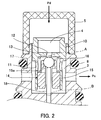
- valve seat-forming member 10 As more clearly shown in Fig. 2, the outer upper periphery of the valve seat-forming member 10 is press-fitted into the open upper end of the upper body 3. A lower portion of the valve seat-forming member 10 extends downward through the crankcase-communicating chamber 8 with a diameter reduced by one step. This reduced diameter portion has communication holes 11 between the inside and the outside of the valve seat-forming member 10. An intermediate portion of an inner part of the valve seat-forming member 10 has a valve hole 12 interconnecting respective space on the discharge chamber and the crankcase sides. The lower rim of the valve hole 12 forms a valve seat 13 at the crankcase side.
- a valve element 14 is axially movably disposed in a lower opening of the valve seat-forming member 10 and includes a holder 15 that can slide along an inner wall of the valve seat-forming member 10.
- a ball 16 is press-fitted into a central portion of the upper end of the holder 15.
- the outer periphery of an upper portion of the holder 15 is reduced in diameter and carries a spring 17 interposed between the valve seat-forming member 10 and the holder 15, for urging the ball 16 in a direction away from the valve seat 13.
- the holder 15 has communication holes 15a between the inside and the outside of the holder 15.
- the ball 16 operates in unison with the holder 15 such that it can be seated on the valve seat 13.
- the discharge pressure Pd introduced from the discharge pressure port 4 is decompressed by passing through a restriction flow passage between the ball 16 and the valve seat 13, whereby the crank pressure Pc is generated.
- the shaft 18 is axially movably inserted into the guide hole 9 in Fig. 1.
- One shaft end extends through the holder 15 and abuts at the ball 16.
- the other shaft end extending downward from the upper body 3.
- the valve element 14 acts based on the principle of a balancing toy. As a result, a lateral motion of the valve element 14 is suppressed, and hence the valve element 14 is capable of axially moving back and forth in a stable state in which lateral load is reduced. Further, since the lateral load on the valve element 14 generated upon axial movement of the valve element 14 is reduced, hysteresis is decreased in the opening and closing characteristics of the control valve and the lateral displacement of the valve element 14 is suppressed. As a result, complete closing of the valve element 14 can reliably be expected.
- An upper open end of a lower body 19 is joined by caulking to a bottom portion of the upper body 3.
- a core 20 of a solenoid 2 is screwed to a lower end of the upper body 3.
- the core 20 has an axial central hole 21, an upper portion with communication holes 22 extending from the outer periphery with the central hole 21, and communication holes 23 in an upper end between the refrigerant passage 7a and the communication hole 22.
- a sleeve 24 with a stopper 25 in the form of a lid fitted in a lower opening of the sleeve 24 is disposed inside the lower body 19.
- An annular bearing member 26 is press-fitted into the stopper 25.
- the core 20 and a plunger 27 are arranged in the sleeve 24.
- the plunger 27 is rigidly fixed to a shaft 28.
- One shaft end extends through the core 20 with clearance into an opening in the lower end of the upper body 3.
- the other shaft end is supported by the bearing member 26. Movement of the plunger 27 relative to the shaft 18 is restricted in one axial direction by a stop ring 29 on the shaft 28.
- the plunger 27 is guided on the shaft 28 to move axially without contact with the sleeve 24.
- Springs 30, 31 are interposed between the core 20 and the plunger 27, and between the plunger 27 and the bearing member 26.
- a yoke 32 Arranged along the outer periphery of the sleeve 24 are a yoke 32, a solenoid coil 33, and a casing 34 surrounding the yoke 32 and the solenoid coil 33, which constitute the solenoid 2 together with the core 20 and the plunger 27.
- a handle 36 supporting a harness 35 is fitted in the casing 34 to close the lower end of the solenoid 2.
- the discharge pressure Pd acts on the ball 16 from above.
- the suction pressure Ps acts on the shaft 18 in abutment with the ball 16, from below, via the clearance between the upper body 3 and the shaft 28. If the diameter of the shaft 18 (i.e. the diameter of the guide hole 9) and the diameter of the valve hole 12 are equal, the effective discharge pressure-receiving area of the ball 16 and the effective suction pressure-receiving area of the shaft 18 are equal as well. Therefore, the crank pressure Pc applied to an intermediate structure formed by making the valve element 14 and the shaft 18 move in unison with each other is cancelled.
- the ball 16 controlling the flow rate into the crankcase forms a differential pressure valve that operates by sensing the differential pressure between the discharge pressure Pd and the suction pressure Ps.
- the difference between the above-mentioned effective pressure-receiving areas is adjusted e.g. by increasing only the dimension of one of them, whereby characteristics (differential pressure crank pressure characteristics) concerning the degree of the influence of the crank pressure on a change in the differential pressure between the discharge pressure and the suction pressure are adjusted such that they become desired characteristics.
- characteristics differential pressure crank pressure characteristics
- a predetermined control current is supplied to the solenoid 2.
- the plunger 27 is attracted by the core 20 with an upward force according to the magnitude of the control current.
- the plunger 27 moves by a predetermined amount.
- This force serves as a set value of the control valve that operates as the differential pressure valve, i.e. senses the differential pressure (Pd-Ps) and controls the flow rate into the crankcase such that the value of the differential pressure is held at a value corresponding to the set value as set by the solenoid 2.
- the control valve allows to obtain a desired "differential pressure • crank pressure characteristics" by adjusting the difference between the effective pressure-receiving area A on the discharge pressure side of the intermediate structure formed by making the valve element 14 move in unison with the shaft 18, like a one-piece structure, and the effective pressure-receiving area B on the suction pressure side of the intermediate structure, as shown in Fig. 2.
- the effective pressure-receiving area A can be adjusted by adjusting the diameter of the valve hole 12.
- the effective pressure-receiving area B on the suction pressure side can be adjusted by adjusting the diameter of the shaft 18 (i.e. the diameter of the guide hole 9).
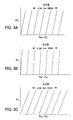
- Fig. 3A represents a case where the effective pressure-receiving areas A, B are equal.
- Fig. 3B represents a case where the effective pressure-receiving area A is smaller than the effective pressure-receiving area B.
- Fig. 3C represents the case where the effective pressure-receiving area A is larger than the effective pressure-receiving area B.
- Fig. 3A the differential pressure (Pd - Ps) is slightly changed under the influence of the crank pressure Pc even when the value of the supplied electric current is fixed.
- the differential pressure (Pd - Ps) varies with the magnitude of the value (Isol) of the electric current.
- the difference between the effective pressure-receiving area A on the discharge pressure side of the intermediate structure formed by making the valve element 14 integral with the shaft 18 and the effective pressure-receiving area B on the suction pressure side of the intermediate structure is adjusted as required.
- This allows to obtain desired "differential pressure • crank pressure characteristics" according to the specifications of the control valve.
- Such changes in the effective pressure-receiving areas have almost no influence on the "electric current • differential pressure characteristics", i.e. the relationship between the magnitude of the supplied electric current and the differential pressure (Pd-Ps), and hence it is possible to realize the changes in the effective pressure-receiving areas with ease.
Landscapes
- Engineering & Computer Science (AREA)
- Mechanical Engineering (AREA)
- General Engineering & Computer Science (AREA)
- Compressors, Vaccum Pumps And Other Relevant Systems (AREA)
- Control Of Positive-Displacement Pumps (AREA)
Applications Claiming Priority (1)
| Application Number | Priority Date | Filing Date | Title |
|---|---|---|---|
| JP2004239161A JP2006057506A (ja) | 2004-08-19 | 2004-08-19 | 可変容量圧縮機用制御弁 |
Publications (2)
| Publication Number | Publication Date |
|---|---|
| EP1628017A2 true EP1628017A2 (de) | 2006-02-22 |
| EP1628017A3 EP1628017A3 (de) | 2006-11-02 |
Family
ID=35064917
Family Applications (1)
| Application Number | Title | Priority Date | Filing Date |
|---|---|---|---|
| EP05017519A Withdrawn EP1628017A3 (de) | 2004-08-19 | 2005-08-11 | Regelventil für einen Kompressor mit veränderlicher Verdrängung |
Country Status (5)
| Country | Link |
|---|---|
| US (1) | US20060039798A1 (de) |
| EP (1) | EP1628017A3 (de) |
| JP (1) | JP2006057506A (de) |
| KR (1) | KR20060050534A (de) |
| CN (1) | CN100436813C (de) |
Cited By (3)
| Publication number | Priority date | Publication date | Assignee | Title |
|---|---|---|---|---|
| EP2913527A1 (de) * | 2014-02-27 | 2015-09-02 | TGK CO., Ltd. | Regelventil für einen verdichter mit variabler verdrängung |
| EP2975266A1 (de) * | 2014-07-18 | 2016-01-20 | TGK CO., Ltd. | Regelventil für einen verdichter mit variabler verdrängung |
| DE102014116214B3 (de) * | 2014-11-06 | 2016-02-04 | Eto Magnetic Gmbh | Proportionalventil, Klimakompressoranordnung sowie Betriebsverfahren |
Families Citing this family (7)
| Publication number | Priority date | Publication date | Assignee | Title |
|---|---|---|---|---|
| JP2008045522A (ja) * | 2006-08-21 | 2008-02-28 | Toyota Industries Corp | 圧縮機における冷媒流量検出構造 |
| JP2008121636A (ja) * | 2006-11-15 | 2008-05-29 | Toyota Industries Corp | 圧縮機における冷媒流量検出構造 |
| JP5149580B2 (ja) * | 2007-09-26 | 2013-02-20 | サンデン株式会社 | 可変容量圧縮機のための容量制御弁、容量制御システム及び可変容量圧縮機 |
| JP2016020682A (ja) * | 2014-06-19 | 2016-02-04 | 株式会社テージーケー | 可変容量圧縮機用制御弁 |
| JP6340501B2 (ja) | 2014-06-19 | 2018-06-13 | 株式会社テージーケー | 可変容量圧縮機用制御弁 |
| JP2016014334A (ja) | 2014-07-01 | 2016-01-28 | 株式会社テージーケー | 可変容量圧縮機用制御弁 |
| EP3059445B1 (de) | 2015-02-23 | 2020-06-24 | TGK CO., Ltd. | Elektromagnetisches regelventil eines verdichters mit variabler verdrängung |
Citations (1)
| Publication number | Priority date | Publication date | Assignee | Title |
|---|---|---|---|---|
| JP2003328936A (ja) | 2002-05-13 | 2003-11-19 | Tgk Co Ltd | 可変容量圧縮機用容量制御弁 |
Family Cites Families (7)
| Publication number | Priority date | Publication date | Assignee | Title |
|---|---|---|---|---|
| US5702235A (en) * | 1995-10-31 | 1997-12-30 | Tgk Company, Ltd. | Capacity control device for valiable-capacity compressor |
| JP3432995B2 (ja) * | 1996-04-01 | 2003-08-04 | 株式会社豊田自動織機 | 可変容量型圧縮機用制御弁 |
| JP2001073939A (ja) * | 1999-08-31 | 2001-03-21 | Toyota Autom Loom Works Ltd | 容量可変型圧縮機の制御弁及び容量可変型圧縮機 |
| JP3963619B2 (ja) * | 1999-11-05 | 2007-08-22 | 株式会社テージーケー | 冷凍サイクルの圧縮容量制御装置 |
| JP3943871B2 (ja) * | 2001-07-25 | 2007-07-11 | 株式会社テージーケー | 可変容量圧縮機および可変容量圧縮機用容量制御弁 |
| JP4152674B2 (ja) * | 2002-06-04 | 2008-09-17 | 株式会社テージーケー | 可変容量圧縮機用容量制御弁 |
| JP2004137980A (ja) * | 2002-10-18 | 2004-05-13 | Tgk Co Ltd | 可変容量圧縮機用容量制御弁 |
-
2004
- 2004-08-19 JP JP2004239161A patent/JP2006057506A/ja active Pending
-
2005
- 2005-08-11 EP EP05017519A patent/EP1628017A3/de not_active Withdrawn
- 2005-08-17 CN CNB2005100905620A patent/CN100436813C/zh not_active Expired - Fee Related
- 2005-08-17 US US11/205,064 patent/US20060039798A1/en not_active Abandoned
- 2005-08-18 KR KR1020050075462A patent/KR20060050534A/ko not_active Withdrawn
Patent Citations (1)
| Publication number | Priority date | Publication date | Assignee | Title |
|---|---|---|---|---|
| JP2003328936A (ja) | 2002-05-13 | 2003-11-19 | Tgk Co Ltd | 可変容量圧縮機用容量制御弁 |
Cited By (11)
| Publication number | Priority date | Publication date | Assignee | Title |
|---|---|---|---|---|
| EP2913527A1 (de) * | 2014-02-27 | 2015-09-02 | TGK CO., Ltd. | Regelventil für einen verdichter mit variabler verdrängung |
| EP2963291A3 (de) * | 2014-02-27 | 2016-01-27 | TGK CO., Ltd. | Regelventil für einen verdichter mit variabler verdrängung |
| EP2977607A1 (de) * | 2014-02-27 | 2016-01-27 | TGK CO., Ltd. | Regelventil für einen verdichter mit variabler verdrängung |
| EP2963292A3 (de) * | 2014-02-27 | 2016-01-27 | TGK CO., Ltd. | Regelventil für einen verdichter mit variabler verdrängung |
| US9512833B2 (en) | 2014-02-27 | 2016-12-06 | Tgk Co., Ltd. | Control valve for variable displacement compressor |
| US9556862B2 (en) | 2014-02-27 | 2017-01-31 | Tgk Co., Ltd. | Control valve for variable displacement compressor |
| US9562524B2 (en) | 2014-02-27 | 2017-02-07 | Tgk Co., Ltd. | Control valve for variable displacement compressor |
| EP2975266A1 (de) * | 2014-07-18 | 2016-01-20 | TGK CO., Ltd. | Regelventil für einen verdichter mit variabler verdrängung |
| DE102014116214B3 (de) * | 2014-11-06 | 2016-02-04 | Eto Magnetic Gmbh | Proportionalventil, Klimakompressoranordnung sowie Betriebsverfahren |
| WO2016071030A1 (de) | 2014-11-06 | 2016-05-12 | Eto Magnetic Gmbh | Proportionalventil, klimakompressoranordnung sowie betriebsverfahren |
| US10316975B2 (en) | 2014-11-06 | 2019-06-11 | Eto Magnetic Gmbh | Proportional valve, air-conditioner compressor arrangement, and operating method |
Also Published As
| Publication number | Publication date |
|---|---|
| US20060039798A1 (en) | 2006-02-23 |
| EP1628017A3 (de) | 2006-11-02 |
| KR20060050534A (ko) | 2006-05-19 |
| CN100436813C (zh) | 2008-11-26 |
| CN1737370A (zh) | 2006-02-22 |
| JP2006057506A (ja) | 2006-03-02 |
Similar Documents
| Publication | Publication Date | Title |
|---|---|---|
| JP4829419B2 (ja) | 可変容量型圧縮機用制御弁 | |
| JP4431462B2 (ja) | 斜板式容量可変型圧縮機および電磁制御弁 | |
| EP1561948A2 (de) | Kontrollventil für einen verstellbaren Taumelscheibenkompressor | |
| CN100396917C (zh) | 用于可变容积式压缩机的控制阀 | |
| EP1582742B1 (de) | Kontrollventil für Kompressoren mit variabler Fördermenge | |
| EP1650435A1 (de) | Regelventil für einen Verdichter variabler Verdrängung | |
| EP1281868B1 (de) | Kapazitätskontrollventil | |
| EP1512871A1 (de) | Kontrollventil für einen verstellbaren Taumelscheibenkompressor | |
| US6682314B2 (en) | Control valve for variable displacement type compressor | |
| US20040086391A1 (en) | Control valve for variable displacement compressor | |
| EP1628017A2 (de) | Regelventil für einen Kompressor mit veränderlicher Verdrängung | |
| JPWO2019142931A1 (ja) | 容量制御弁 | |
| EP1602828A2 (de) | Kontrollventil für einen verstellbaren Taumelscheibenkompressor | |
| EP1574710B1 (de) | Regelventil für einen Kompressor mit veränderlicher Verdrängung | |
| US6783332B2 (en) | Control valve of variable displacement compressor with pressure sensing member | |
| US7437881B2 (en) | Control valve for variable displacement compressor | |
| US20050220631A1 (en) | Control valve for variable displacement compressor | |
| US6974311B2 (en) | Control valve | |
| US20060083625A1 (en) | Control valve for variable displacement compressor | |
| US20060045758A1 (en) | Control valve for variable displacement compressor | |
| JP2008297974A (ja) | 可変容量型圧縮機用制御弁 | |
| JP2006188961A (ja) | 可変容量圧縮機用制御弁 | |
| JP2002364534A (ja) | 感圧電磁制御弁 | |
| JP4173019B2 (ja) | 可変容量圧縮機用容量制御弁 | |
| JP2007154718A (ja) | 可変容量圧縮機用制御弁 |
Legal Events
| Date | Code | Title | Description |
|---|---|---|---|
| PUAI | Public reference made under article 153(3) epc to a published international application that has entered the european phase |
Free format text: ORIGINAL CODE: 0009012 |
|
| AK | Designated contracting states |
Kind code of ref document: A2 Designated state(s): AT BE BG CH CY CZ DE DK EE ES FI FR GB GR HU IE IS IT LI LT LU LV MC NL PL PT RO SE SI SK TR |
|
| AX | Request for extension of the european patent |
Extension state: AL BA HR MK YU |
|
| PUAL | Search report despatched |
Free format text: ORIGINAL CODE: 0009013 |
|
| AK | Designated contracting states |
Kind code of ref document: A3 Designated state(s): AT BE BG CH CY CZ DE DK EE ES FI FR GB GR HU IE IS IT LI LT LU LV MC NL PL PT RO SE SI SK TR |
|
| AX | Request for extension of the european patent |
Extension state: AL BA HR MK YU |
|
| 17P | Request for examination filed |
Effective date: 20070502 |
|
| AKX | Designation fees paid |
Designated state(s): DE FR |
|
| 17Q | First examination report despatched |
Effective date: 20091006 |
|
| STAA | Information on the status of an ep patent application or granted ep patent |
Free format text: STATUS: THE APPLICATION IS DEEMED TO BE WITHDRAWN |
|
| 18D | Application deemed to be withdrawn |
Effective date: 20100217 |