EP1628021A1 - Dispositif de verrouillage d'au moins deux goupilles à insérer dans des perçages de plaques - Google Patents
Dispositif de verrouillage d'au moins deux goupilles à insérer dans des perçages de plaques Download PDFInfo
- Publication number
- EP1628021A1 EP1628021A1 EP05016471A EP05016471A EP1628021A1 EP 1628021 A1 EP1628021 A1 EP 1628021A1 EP 05016471 A EP05016471 A EP 05016471A EP 05016471 A EP05016471 A EP 05016471A EP 1628021 A1 EP1628021 A1 EP 1628021A1
- Authority
- EP
- European Patent Office
- Prior art keywords
- bolts
- bolt
- designed
- locking arrangement
- plate
- Prior art date
- Legal status (The legal status is an assumption and is not a legal conclusion. Google has not performed a legal analysis and makes no representation as to the accuracy of the status listed.)
- Withdrawn
Links
- 210000002105 tongue Anatomy 0.000 claims description 20
- 230000015572 biosynthetic process Effects 0.000 description 2
- 238000005755 formation reaction Methods 0.000 description 2
- 238000004519 manufacturing process Methods 0.000 description 2
- 229910001018 Cast iron Inorganic materials 0.000 description 1
- 230000000903 blocking effect Effects 0.000 description 1
- 239000002184 metal Substances 0.000 description 1
- 229910052751 metal Inorganic materials 0.000 description 1
Images

Classifications
-
- F—MECHANICAL ENGINEERING; LIGHTING; HEATING; WEAPONS; BLASTING
- F16—ENGINEERING ELEMENTS AND UNITS; GENERAL MEASURES FOR PRODUCING AND MAINTAINING EFFECTIVE FUNCTIONING OF MACHINES OR INSTALLATIONS; THERMAL INSULATION IN GENERAL
- F16B—DEVICES FOR FASTENING OR SECURING CONSTRUCTIONAL ELEMENTS OR MACHINE PARTS TOGETHER, e.g. NAILS, BOLTS, CIRCLIPS, CLAMPS, CLIPS OR WEDGES; JOINTS OR JOINTING
- F16B19/00—Bolts without screw-thread; Pins, including deformable elements; Rivets
Definitions
- the invention relates to a locking arrangement of at least two bolts.
- the bolts are designed and arranged to extend through bores in at least one plate and in an extension plate.
- Each bolt includes a key located at one end of the bolt. The key serves to prevent axial movement of the bolt.
- Two or more bolts are used for instance on agricultural vehicles and equipment to pivotally connect two or more elements.
- the bolts are inserted in bores of the elements and secured in axial direction to prevent falling out of the bores.
- the bolt comprises a head on one end and a key on the other end securing against fall out.
- the key is inserted into a cross hole of the other end of the bolt.
- the bolts have to be designed not to rotate, otherwise a substantial wear occurs with respect of the bores. This is especially the case if one of the elements is made of cast iron.
- a locking arrangement for bolts is known from a leaflet of the company Hans Sauter GmbH "Frontkraftheber und Frontzapfwelle für Claas-Traktoren” (front power lift and front take off shaft for Claas tractors).
- Lower elements of a three-point linkage of a front power lift are shown comprising the frame of the vehicle and two lower elements connected with each other by two bolts.
- One of the bolts always remains in its position, while the other bolt can be extracted from its bore when necessary. In this way there are two positions between the frame and the lower elements, one fixed position for transport and one floating position.
- the frame includes a bore in which the other bolt has to be inserted.
- the bolts are designed to have a head in the shape of a cam fitting into an opening in the outside of the frame.
- a locking arrangement of at least two bolts the bolts being designed and arranged to extend through bores in at least one plate and in an extension plate and including a key located at one end of each bolt, wherein the bolts have heads located at the other end of each bolt, each head being rigidly connected with its bolt and extending in a radial direction with respect to the axis of the bolt, and the heads engaging each other and being designed with interlocking formations (e.g. a cooperating tongue and groove) to prevent a rotational movement of the at least two bolts.
- interlocking formations e.g. a cooperating tongue and groove
- the heads may be designed similar to a self blocking pair of toothed wheels. In this manner the bolts block and secure each other. No further element is needed to complete the locking arrangement.
- the locking arrangement is not limited to two bolts. A larger number of bolts positioned in a group may be secured in this manner.
- the amount of possible motion of the bolts in a rotational direction only depends on the accuracy with which the interengaging heads are manufactured.
- the security against rotation of the bolts can be increased by making the play between the interlocking formations as little as possible.
- Claim 2 describes an embodiment of the invention in which the heads have a simple interengaging tongue and groove design.
- the heads may extend to bridge a large distance between the axes of the bolts.
- the bolts may therefore be used for varying distances between the axes.
- Claim 3 describes an embodiment of the invention in which the heads of the bolts may be manufactured without substantial efforts with respect to accuracy.
- the heads of the at least two bolts are designed to have an identical fork-like shape with two tongues and one groove, the tongues and the groove having the same width. Due to the identical configuration the manufacture, the handling and the storing of the bolts is substantially simplified.
- the locking arrangement may also be designed so that the bolts can be positioned in a first pair of bores to lock the at least one plate and extension plate in a fixed position relative to each other with their head engaged to prevent rotational motion of the bolts, and one of the bolts can alternatively be arranged to extend through a further bore in one of said at least one plate and extension plate and through a slot in the other of the extension plate and said at least one plate to permit pivoting between the plates about the other bolt with the heads engaged to prevent said rotational motion of the bolts.
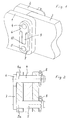
- an extension plate 3 In the embodiment shown in Figs. 1 and 2 between two plates 1 and 2 is positioned an extension plate 3.
- the extension plate 3 may be mounted and demounted without using special tools.
- the plates 1 and 2 and the extension plate 3 are formed from sheet metal and each have two aligning bores located one above the other.
- Two bolts 4, 5 are inserted into the bores. Both of the bolts 4, 5 have heads (shackles) 6, 7 extending in radial direction with respect to the axes 4a, 5a of the bolts.
- a cross hole is provided in which a key 8 is inserted serving to prevent falling out.
- the heads 6, 7 are designed to fit to each other and to block rotational movement of the bolts. This design is similar to a pair of toothed wheels meshing with each other, but having a configuration to block any rotational movement.
- the head 6 of the upper bolt 4 is designed as a tongue 9 extending straight for a substantial length in a radial direction
- the head 7 of the lower bolt 5 is designed with a fork-like shape extending in a radial direction and comprises a groove 10.
- the width of the groove 10 is adapted to the width of the tongue 9 without substantial play between.
- the tongue 9 is placed in the groove 10 and a securing against rotational movement thus occurs. This securing remains as long as a sufficient overlapping between the tongue 9 and the groove 10 takes place.
- 5 may be used for varying distances between the axes 4a and 5a.
- the embodiment of Fig. 3 shows bolts 11 having identical heads 12.
- Both fork shaped parts of the heads 12 are designed in the form of tongues 13 having the same dimensions.
- the grooves 14 between of the tongues 13 of heads 12 fit with the tongues 13 as described above. Consequently, there are two possible positions between the heads when mounting the bolts.
- the upper fork In the second position (not shown) the upper fork is twined through 180 degrees about a vertical axis so that the right-hand tongue 13 of the upper fork of Figure 3 is now positioned to the left of the left-hand tongue 13 of the lower fork in Figure 3.
- FIG. 1 the extension plate 3 has to be connected between the plates 1 and 2 in a fixed manner.
- FIG. 4 shows an embodiment in which the extension plate 15 may be connected with the plates 16 in a first fixed position and in a second pivotal or floating position.
- the plates 16 comprise further aligned bores 19 and the extension plate 15 has an elongated slot 20 to receive the lower bolt 5 in the floating position between the extension plate 15 and the plates 16.
- the distance between the axis of the bore 17 of upper bolt 4 to the bores 19 of the plates 16 is different to the distance between the bores 17 and 18 to avoid faults when mounting.
- the bolt 5 is inserted into the bore 19 having a larger distance from the bolt 4 compared with the fix position of the bolts 4 and 5 shown in dash-dotted lines. In both positions rotational movement of the bolts 4, 5 with respect to the bores 17 and 18 and (some) of the bores 17 and19 respectively is prevented by the interengaging of the heads.
Landscapes
- Engineering & Computer Science (AREA)
- General Engineering & Computer Science (AREA)
- Mechanical Engineering (AREA)
- Pivots And Pivotal Connections (AREA)
- Forklifts And Lifting Vehicles (AREA)
Applications Claiming Priority (1)
| Application Number | Priority Date | Filing Date | Title |
|---|---|---|---|
| GB0418314A GB0418314D0 (en) | 2004-08-17 | 2004-08-17 | Locking arrangement for at least two bolts to be inserted into bores of plates |
Publications (1)
| Publication Number | Publication Date |
|---|---|
| EP1628021A1 true EP1628021A1 (fr) | 2006-02-22 |
Family
ID=33017632
Family Applications (1)
| Application Number | Title | Priority Date | Filing Date |
|---|---|---|---|
| EP05016471A Withdrawn EP1628021A1 (fr) | 2004-08-17 | 2005-07-29 | Dispositif de verrouillage d'au moins deux goupilles à insérer dans des perçages de plaques |
Country Status (2)
| Country | Link |
|---|---|
| EP (1) | EP1628021A1 (fr) |
| GB (2) | GB0418314D0 (fr) |
Cited By (1)
| Publication number | Priority date | Publication date | Assignee | Title |
|---|---|---|---|---|
| EP2031188A1 (fr) | 2007-08-30 | 2009-03-04 | Snecma | Etage d'aubes à calage variable pour une turbomachine |
Citations (4)
| Publication number | Priority date | Publication date | Assignee | Title |
|---|---|---|---|---|
| DE23532C (de) * | O. EDLINGER in Geitheim i./S | Schraubensicherung | ||
| US957931A (en) * | 1910-02-14 | 1910-05-17 | Henry J Bond | Nut-lock. |
| DE3418220A1 (de) * | 1984-05-16 | 1985-11-21 | Walter Kieninger KG, 7630 Lahr | Positionssicherbare schraube |
| US4822197A (en) * | 1987-02-18 | 1989-04-18 | Demartino John D | Quick connect/disconnect assembly |
Family Cites Families (1)
| Publication number | Priority date | Publication date | Assignee | Title |
|---|---|---|---|---|
| GB2394265A (en) * | 2002-10-19 | 2004-04-21 | Ray Mason | Wheel Safety Device |
-
2004
- 2004-08-17 GB GB0418314A patent/GB0418314D0/en not_active Ceased
-
2005
- 2005-07-26 GB GB0515272A patent/GB2417303A/en not_active Withdrawn
- 2005-07-29 EP EP05016471A patent/EP1628021A1/fr not_active Withdrawn
Patent Citations (4)
| Publication number | Priority date | Publication date | Assignee | Title |
|---|---|---|---|---|
| DE23532C (de) * | O. EDLINGER in Geitheim i./S | Schraubensicherung | ||
| US957931A (en) * | 1910-02-14 | 1910-05-17 | Henry J Bond | Nut-lock. |
| DE3418220A1 (de) * | 1984-05-16 | 1985-11-21 | Walter Kieninger KG, 7630 Lahr | Positionssicherbare schraube |
| US4822197A (en) * | 1987-02-18 | 1989-04-18 | Demartino John D | Quick connect/disconnect assembly |
Cited By (2)
| Publication number | Priority date | Publication date | Assignee | Title |
|---|---|---|---|---|
| EP2031188A1 (fr) | 2007-08-30 | 2009-03-04 | Snecma | Etage d'aubes à calage variable pour une turbomachine |
| JP2009057965A (ja) * | 2007-08-30 | 2009-03-19 | Snecma | ターボ機械用の可変ピッチ翼の段 |
Also Published As
| Publication number | Publication date |
|---|---|
| GB0418314D0 (en) | 2004-09-15 |
| GB0515272D0 (en) | 2005-08-31 |
| GB2417303A (en) | 2006-02-22 |
Similar Documents
| Publication | Publication Date | Title |
|---|---|---|
| US9863117B2 (en) | Coupler for earth moving or materials handling machine | |
| US8904677B2 (en) | Locking pin assembly | |
| US20070152417A1 (en) | Dual axis bushing assembly and method for camber and caster adjustment | |
| EP2964840B1 (fr) | Goupille de fixation et ensemble de fixation de goupille | |
| EP1805058B1 (fr) | Dispositif de reglage et siege de vehicule | |
| US20080264891A1 (en) | Automatically foldable coupler | |
| CA2526429A1 (fr) | Ensemble combine rondelle de blocage, coussinet et tige poussoir | |
| EP2728073B1 (fr) | Chargeur | |
| WO2011126686A1 (fr) | Vanne avec plaque à encoches ayant une robustesse accrue | |
| US20170326910A1 (en) | Wheel retention system | |
| EP1932692B1 (fr) | Dispositif d'articulation, particulièrement pour un bras de suspension d'un véhicule à moteur | |
| EP1628021A1 (fr) | Dispositif de verrouillage d'au moins deux goupilles à insérer dans des perçages de plaques | |
| US8075005B1 (en) | Wheel alignment apparatus | |
| EP0693250B1 (fr) | Arrangement de mesure d'effort de traction pour attelage d'outil | |
| HK1046719A1 (en) | Driving flange for a cardan joint and articulated shaft | |
| CN107208432B (zh) | 筒锁 | |
| EP1935759A3 (fr) | Mécanisme de blocage de la direction des roues arrière | |
| EP2397627A2 (fr) | Dispositif de couplage et de découplage d'une poignée extérieure de porte | |
| US5501087A (en) | Rotary locking cylinder for a safety lock | |
| EP0641686A2 (fr) | Mécanismes pour rétroviseurs | |
| RU2562032C2 (ru) | Поворотный язычок и замок для открывающейся части автотранспортного средства | |
| EP1195314B1 (fr) | Appareil pour déterminer l'angle de braquage pour véhicules | |
| EP4098528B1 (fr) | Serrure en châssis | |
| EP2048290B1 (fr) | Dispositif de couplage avec verrouillage semi-automatique pour le couplage amovible d'un outil a un engin de travail | |
| DE202006008462U1 (de) | Anhängerkupplung |
Legal Events
| Date | Code | Title | Description |
|---|---|---|---|
| PUAI | Public reference made under article 153(3) epc to a published international application that has entered the european phase |
Free format text: ORIGINAL CODE: 0009012 |
|
| AK | Designated contracting states |
Kind code of ref document: A1 Designated state(s): AT BE BG CH CY CZ DE DK EE ES FI FR GB GR HU IE IS IT LI LT LU LV MC NL PL PT RO SE SI SK TR |
|
| AX | Request for extension of the european patent |
Extension state: AL BA HR MK YU |
|
| STAA | Information on the status of an ep patent application or granted ep patent |
Free format text: STATUS: THE APPLICATION HAS BEEN WITHDRAWN |
|
| 18W | Application withdrawn |
Effective date: 20060407 |