EP1628047B1 - Wähleinrichtung für ein Kraftfahrzeuggetriebe - Google Patents
Wähleinrichtung für ein Kraftfahrzeuggetriebe Download PDFInfo
- Publication number
- EP1628047B1 EP1628047B1 EP05255004A EP05255004A EP1628047B1 EP 1628047 B1 EP1628047 B1 EP 1628047B1 EP 05255004 A EP05255004 A EP 05255004A EP 05255004 A EP05255004 A EP 05255004A EP 1628047 B1 EP1628047 B1 EP 1628047B1
- Authority
- EP
- European Patent Office
- Prior art keywords
- selector
- transmission control
- control unit
- transmission
- vehicle
- Prior art date
- Legal status (The legal status is an assumption and is not a legal conclusion. Google has not performed a legal analysis and makes no representation as to the accuracy of the status listed.)
- Expired - Lifetime
Links
Images

Classifications
-
- B—PERFORMING OPERATIONS; TRANSPORTING
- B60—VEHICLES IN GENERAL
- B60K—ARRANGEMENT OR MOUNTING OF PROPULSION UNITS OR OF TRANSMISSIONS IN VEHICLES; ARRANGEMENT OR MOUNTING OF PLURAL DIVERSE PRIME-MOVERS IN VEHICLES; AUXILIARY DRIVES FOR VEHICLES; INSTRUMENTATION OR DASHBOARDS FOR VEHICLES; ARRANGEMENTS IN CONNECTION WITH COOLING, AIR INTAKE, GAS EXHAUST OR FUEL SUPPLY OF PROPULSION UNITS IN VEHICLES
- B60K20/00—Arrangement or mounting of change-speed gearing control devices in vehicles
- B60K20/02—Arrangement or mounting of change-speed gearing control devices in vehicles of initiating means
- B60K20/04—Arrangement or mounting of change-speed gearing control devices in vehicles of initiating means floor mounted
-
- B—PERFORMING OPERATIONS; TRANSPORTING
- B60—VEHICLES IN GENERAL
- B60K—ARRANGEMENT OR MOUNTING OF PROPULSION UNITS OR OF TRANSMISSIONS IN VEHICLES; ARRANGEMENT OR MOUNTING OF PLURAL DIVERSE PRIME-MOVERS IN VEHICLES; AUXILIARY DRIVES FOR VEHICLES; INSTRUMENTATION OR DASHBOARDS FOR VEHICLES; ARRANGEMENTS IN CONNECTION WITH COOLING, AIR INTAKE, GAS EXHAUST OR FUEL SUPPLY OF PROPULSION UNITS IN VEHICLES
- B60K35/00—Instruments specially adapted for vehicles; Arrangement of instruments in or on vehicles
- B60K35/10—Input arrangements, i.e. from user to vehicle, associated with vehicle functions or specially adapted therefor
-
- B—PERFORMING OPERATIONS; TRANSPORTING
- B60—VEHICLES IN GENERAL
- B60K—ARRANGEMENT OR MOUNTING OF PROPULSION UNITS OR OF TRANSMISSIONS IN VEHICLES; ARRANGEMENT OR MOUNTING OF PLURAL DIVERSE PRIME-MOVERS IN VEHICLES; AUXILIARY DRIVES FOR VEHICLES; INSTRUMENTATION OR DASHBOARDS FOR VEHICLES; ARRANGEMENTS IN CONNECTION WITH COOLING, AIR INTAKE, GAS EXHAUST OR FUEL SUPPLY OF PROPULSION UNITS IN VEHICLES
- B60K35/00—Instruments specially adapted for vehicles; Arrangement of instruments in or on vehicles
- B60K35/20—Output arrangements, i.e. from vehicle to user, associated with vehicle functions or specially adapted therefor
- B60K35/25—Output arrangements, i.e. from vehicle to user, associated with vehicle functions or specially adapted therefor using haptic output
-
- F—MECHANICAL ENGINEERING; LIGHTING; HEATING; WEAPONS; BLASTING
- F16—ENGINEERING ELEMENTS AND UNITS; GENERAL MEASURES FOR PRODUCING AND MAINTAINING EFFECTIVE FUNCTIONING OF MACHINES OR INSTALLATIONS; THERMAL INSULATION IN GENERAL
- F16H—GEARING
- F16H59/00—Control inputs to control units of change-speed- or reversing-gearings for conveying rotary motion
- F16H59/02—Selector apparatus
- F16H59/0278—Constructional features of the selector lever, e.g. grip parts, mounting or manufacturing
-
- F—MECHANICAL ENGINEERING; LIGHTING; HEATING; WEAPONS; BLASTING
- F16—ENGINEERING ELEMENTS AND UNITS; GENERAL MEASURES FOR PRODUCING AND MAINTAINING EFFECTIVE FUNCTIONING OF MACHINES OR INSTALLATIONS; THERMAL INSULATION IN GENERAL
- F16H—GEARING
- F16H59/00—Control inputs to control units of change-speed- or reversing-gearings for conveying rotary motion
- F16H59/02—Selector apparatus
- F16H59/08—Range selector apparatus
-
- F—MECHANICAL ENGINEERING; LIGHTING; HEATING; WEAPONS; BLASTING
- F16—ENGINEERING ELEMENTS AND UNITS; GENERAL MEASURES FOR PRODUCING AND MAINTAINING EFFECTIVE FUNCTIONING OF MACHINES OR INSTALLATIONS; THERMAL INSULATION IN GENERAL
- F16H—GEARING
- F16H61/00—Control functions within control units of change-speed- or reversing-gearings for conveying rotary motion ; Control of exclusively fluid gearing, friction gearing, gearings with endless flexible members or other particular types of gearing
- F16H61/12—Detecting malfunction or potential malfunction, e.g. fail safe ; Circumventing or fixing failures
-
- F—MECHANICAL ENGINEERING; LIGHTING; HEATING; WEAPONS; BLASTING
- F16—ENGINEERING ELEMENTS AND UNITS; GENERAL MEASURES FOR PRODUCING AND MAINTAINING EFFECTIVE FUNCTIONING OF MACHINES OR INSTALLATIONS; THERMAL INSULATION IN GENERAL
- F16H—GEARING
- F16H61/00—Control functions within control units of change-speed- or reversing-gearings for conveying rotary motion ; Control of exclusively fluid gearing, friction gearing, gearings with endless flexible members or other particular types of gearing
- F16H61/18—Preventing unintentional or unsafe shift, e.g. preventing manual shift from highest gear to reverse gear
-
- G—PHYSICS
- G05—CONTROLLING; REGULATING
- G05G—CONTROL DEVICES OR SYSTEMS INSOFAR AS CHARACTERISED BY MECHANICAL FEATURES ONLY
- G05G1/00—Controlling members, e.g. knobs or handles; Assemblies or arrangements thereof; Indicating position of controlling members
- G05G1/08—Controlling members for hand actuation by rotary movement, e.g. hand wheels
- G05G1/087—Controlling members for hand actuation by rotary movement, e.g. hand wheels retractable; Flush control knobs
-
- G—PHYSICS
- G05—CONTROLLING; REGULATING
- G05G—CONTROL DEVICES OR SYSTEMS INSOFAR AS CHARACTERISED BY MECHANICAL FEATURES ONLY
- G05G5/00—Means for preventing, limiting or returning the movements of parts of a control mechanism, e.g. locking controlling member
- G05G5/005—Means for preventing, limiting or returning the movements of parts of a control mechanism, e.g. locking controlling member for preventing unintentional use of a control mechanism
-
- G—PHYSICS
- G05—CONTROLLING; REGULATING
- G05G—CONTROL DEVICES OR SYSTEMS INSOFAR AS CHARACTERISED BY MECHANICAL FEATURES ONLY
- G05G5/00—Means for preventing, limiting or returning the movements of parts of a control mechanism, e.g. locking controlling member
- G05G5/06—Means for preventing, limiting or returning the movements of parts of a control mechanism, e.g. locking controlling member for holding members in one or a limited number of definite positions only
-
- B—PERFORMING OPERATIONS; TRANSPORTING
- B60—VEHICLES IN GENERAL
- B60K—ARRANGEMENT OR MOUNTING OF PROPULSION UNITS OR OF TRANSMISSIONS IN VEHICLES; ARRANGEMENT OR MOUNTING OF PLURAL DIVERSE PRIME-MOVERS IN VEHICLES; AUXILIARY DRIVES FOR VEHICLES; INSTRUMENTATION OR DASHBOARDS FOR VEHICLES; ARRANGEMENTS IN CONNECTION WITH COOLING, AIR INTAKE, GAS EXHAUST OR FUEL SUPPLY OF PROPULSION UNITS IN VEHICLES
- B60K2360/00—Indexing scheme associated with groups B60K35/00 or B60K37/00 relating to details of instruments or dashboards
- B60K2360/126—Rotatable input devices for instruments
-
- F—MECHANICAL ENGINEERING; LIGHTING; HEATING; WEAPONS; BLASTING
- F16—ENGINEERING ELEMENTS AND UNITS; GENERAL MEASURES FOR PRODUCING AND MAINTAINING EFFECTIVE FUNCTIONING OF MACHINES OR INSTALLATIONS; THERMAL INSULATION IN GENERAL
- F16H—GEARING
- F16H59/00—Control inputs to control units of change-speed- or reversing-gearings for conveying rotary motion
- F16H59/02—Selector apparatus
- F16H59/08—Range selector apparatus
- F16H2059/081—Range selector apparatus using knops or discs for rotary range selection
-
- H—ELECTRICITY
- H01—ELECTRIC ELEMENTS
- H01H—ELECTRIC SWITCHES; RELAYS; SELECTORS; EMERGENCY PROTECTIVE DEVICES
- H01H3/00—Mechanisms for operating contacts
- H01H3/02—Operating parts, i.e. for operating driving mechanism by a mechanical force external to the switch
- H01H2003/0266—Operating part bringable in an inoperative position by an electrical drive
-
- H—ELECTRICITY
- H01—ELECTRIC ELEMENTS
- H01H—ELECTRIC SWITCHES; RELAYS; SELECTORS; EMERGENCY PROTECTIVE DEVICES
- H01H3/00—Mechanisms for operating contacts
- H01H3/02—Operating parts, i.e. for operating driving mechanism by a mechanical force external to the switch
- H01H3/08—Turn knobs
- H01H2003/085—Retractable turn knobs, e.g. flush mounted
Definitions
- the present invention relates to a selector mechanism for a motor vehicle transmission, more specifically an automatic or semi-automatic vehicle transmission actuated by shift-by-wire, as known from US-A-2004/0045391 .
- a selector mechanism generally comprise a selector connected to position sensors so as to select a selector mode, for instance Park (P), Reverse (R), Neutral (N) or Drive (D).
- the position sensors are connected to a transmission control unit supplying control signals to an actuator such as a solenoid and a motor in order to drive a transmission in accordance with output signals from the position sensors.
- Such vehicle transmissions when operated by shift-by-wire commonly include a wide variety of sensors, switches, and other controls. In the event that any of these components fail, the transmission may fail to function. If such a failure is detected, the transmission control unit switches to a failure or 'limp home' mode which is designed to ensure that, as far as possible, the vehicle will be drivable and safe. Generally in this mode the transmission control will attempt to maintain the current gear and the failure is indicated to the driver by means of a warning light or text message.
- selector mechanism According to the particular type of selector mechanism, several solutions have been proposed to overcome this problem.
- One solution is disclosed on the Aston MartinTM DB9TM where the selector takes the form of individual switches on the dashboard, each for selecting an operating mode for the transmission.
- the transmission control unit stops the engine if the driver selects an operating mode which is not available.
- the driver In the other forms of selector, i.e. a lever or a rotary switch, the driver must move the selector through a Neutral position to get a Drive position or a Reverse position. In such cases, if the transmission is in limp-home mode and the driver moves the selector towards a mode which is unavailable the transmission control unit will shift the transmission to Neutral.
- Both of these known types of solution have certain inherent disadvantages for driver convenience and safety.
- the present invention has as an object the provision of an improved selector mechanism for a vehicle transmission having an improved interaction with the driver when the transmission is in a limp-home mode.
- a selector mechanism for vehicle transmission driven by an engine having a housing, a selector movable in the housing between a number of selector positions each associated with a respective operating mode of the transmission, sensors for sensing the position of the selector and generating selector signals to a transmission control unit which in use supplies control signals to the transmission, and a retractor actuator which in use is controlled by the transmission control unit to displace the selector between an active position where it can be manually moved between the selector position by the driver of the vehicle, and an inactive position in which it is retracted inside the housing where it cannot be readily moved by the driver.
- the selector is a rotary switch.
- the selector mechanism further comprising a drive means which in use is connected to the transmission control unit to move the selector from a selector position selected by the driver to another selector position representative of the operating mode of the transmission.
- the drive means is operable to prevent manual movement of the selector according to the state of the vehicle, i.e. in Park position.
- the invention also provides, according to second aspect threreof, a transmission control system for a motor vehicle transmission having a transmission control unit which in use is connected to a communication port at which data relating to the vehicle's operation are available and including a selector mechanism which is in accordance with said first aspect.
- the invention also provides, according to a third aspect thereof, a method of controlling a selector mechanism according to said first aspect when .installed in a motor vehicle, and the transmission control unit is in receipt of a data relating to the operational state of the vehicle, in which, if the transmission control unit detects or receives a failure signal, the transmission control unit sends a command to the retractor actuator to move the selector towards the inactive position from the active position.
- the method includes sending a command from the transmission control unit to the retractor actuator to move the selector to the active position when the engine is running and to move the selector to the inactive position when the engine is stopped.
- the transmission control unit determines after receiving a signal of the sensors, whether the selector mode is available and if the selector mode is unavailable the transmission control sends a command to the drive means to return the selector to the previous gear position.
- a motor vehicle front passenger compartment having a driver's seat 1, a steering wheel 2 and a centre console 3 mounted between the driver's seat 1 and a passenger seat 4.
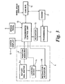
- a selector mechanism 5 for actuating an automatic vehicle transmission 11 which is mounted to the vehicle and driven by an engine 17 ( Fig.3 ).
- the vehicle comprises also a brake pedal 6 located in front of the driver's seat 1 and a device for starting the engine (not shown).
- the selector mechanism 5 includes a housing 7 forming part of the console 3 and a rotary switch 5a with a pointer 8.
- the rotary switch 5a can be grasped by the driver and rotated around a vertical axis so that to select the operating mode of the transmission by pointing the pointer 8 towards indicia constituting the letters PRND corresponding to Park (P), Reverse (R), Neutral (N) and Drive (D) modes respectively in the automatic transmission.
- P Park
- R Reverse
- N Neutral
- D Drive
- the rotary switch 5a is connected to position sensors 9 such as electrical contactors which are mounted in the housing 7 in order to detect a position of the rotary switch 5a and to transmit an input to a transmission control unit 10.
- the transmission control unit 10 includes a known processing logic circuit which is utilized for effecting automatic gear shifts within the transmission 11 in a known manner.
- the transmission control unit is connected to a CAN bus 12 which allows it to communicate with other control units located in the vehicle, e.g. an engine control unit.
- each system makes available on the CAN bus data from the sensors associated with it, data relating to its own operation and data relating to the vehicle's operation which it has derived from the information available to it. Therefore the transmission control unit receives over the CAN bus the signals from wheel speed sensors and the brake pedal.
- the transmission control unit 10 is also connected to a driver display 13 in order to indicate the currently engaged gear of the transmission and possibly any fault of the transmission.
- the rotary switch 5a includes a locking device 14 controlled by the transmission control unit 10 for preventing rotary switch 5a movement in any selecting position if the brake pedal 6 is not depressed, in particular when the rotary switch 5a is in Park position.
- the transmission control unit 10 and the selector mechanism 5 as so far described are conventional.
- a brake detection signal is sent over the CAN bus 12 and receiving by the transmission control unit 10 which unlocks the rotary switch 5a so that the driver can select an appropriate transmission mode.
- the transmission control unit 10 checks the availability of the request and shifts the transmission by sending a command to an actuator 15.
- the transmission control unit 10 switches to a failure or 'limp home' mode which is designed to ensure that, as far as possible, the vehicle will be drivable and safe. In this limp-home mode the transmission control unit 10 sends a warning to the driver display 13 and only the current gear ratio is available or Neutral.
- the selector mechanism 5 includes an actuator, conveniently referred to as the retractor actuator 16, e.g. an electric motor, controlled by the transmission unit control 10 that enables to retract the rotary switch 5a inside the housing 7 into an inactive position, as show Fig.2 , where it cannot be readily moved by the driver.
- the retractor actuator 16 e.g. an electric motor
- the retractor actuator 16 may also be controlled by the transmission control unit 10 when the engine 17 is started or stopped.
- Starting the engine causes the rotary switch 5a to rise from the housing 7 ( Fig.1 ) while stopping the engine causes the rotary switch 5a to drop into the housing 7 ( Fig. 2 ).
- the selector 5a can be displaced either to an inactive position in which it is retracted inside the housing 7 when the driver turns the engine ignition off or an active position in which it is projects outside the housing 7 when the driver turns the engine ignition on.
- the selector mechanism 5 may also include a second actuator or drive means for rotating the rotary switch 5a in cases where an inappropriate selector mode position (PRND) has been selected by the driver.
- PRND selector mode position
- the position sensor 9 sends a signal to the transmission control unit 10. If the transmission control unit 10 accepts the request, then the transmission 11 mode is changed accordingly. If the transmission control unit 10 rejects the request then it sends a signal to the second actuator to rotate the rotary switch 5a to the previous position (PRND). For example, if Reverse is selected when the vehicle is moving forward, the transmission control unit 10 sends a command to the retractor actuator 16 to return the selector 5a to the previous mode.
- This method of controlling the rotary switch 5a enables the provision of a shift-by-wire selector which has multi-stable positions giving, from the driver's viewpoint, a selector mechanism close to the conventional automatic transmission selector lever.
- the actuator can be an electric motor which is either energised to prevent the rotation of the rotary switch 5a or de-energised to enable rotation.
- the selector as described in the present example is a rotary switch comprising a PRND selector
- a manual mode position M can be added.
- the gear ratios can be controlled in a pulse manner, e.g. by a pair of paddles located near the steering wheel, to select engage the next highest (+) or lowest (-) forward gear ratio.
- the transmission control unit may send a command to the drive means so as to rotate the rotary switch from a Drive position mode to a manual position mode when the driver starts to use the paddles.
- the rotary switch could be replaced by a lever moving about a horizontal axis, e.g. in a fore and aft plane.
- the selector mechanism could include other functions mounted in the same housing, e.g. an engine start button or a driving mode selector (casual driving, highway driving, driving on snow, etc.).
Landscapes
- Engineering & Computer Science (AREA)
- General Engineering & Computer Science (AREA)
- Mechanical Engineering (AREA)
- Physics & Mathematics (AREA)
- General Physics & Mathematics (AREA)
- Automation & Control Theory (AREA)
- Chemical & Material Sciences (AREA)
- Combustion & Propulsion (AREA)
- Transportation (AREA)
- Gear-Shifting Mechanisms (AREA)
- Control Of Transmission Device (AREA)
Claims (8)
- Wählschaltermechanismus (5) für eine von einem Motor (17) angetriebene Fahrzeugkraftübertragung (11), wobei der Wählschaltermechanismus (5) mit einem Gehäuse (7), einem Wählschalter (5a), der im Gehäuse (7) zwischen einer Anzahl von Wählschalterpositionen bewegbar ist, die jeweils einem jeweiligen Betriebsmodus der Kraftübertragung zugeordnet sind, sowie mit Sensoren (9) zum Abfühlen der Position des Wählschalters (5a) und zum Erzeugen von Wählschaltersignalen an eine Kraftübertragungssteuereinheit (10) ausgestattet ist, die im Gebrauch Steuersignale an die Kraftübertragung (11) sendet, wobei der Wählschalter (5a) zwischen einer aktiven Position, in der er vom Fahrer des Fahrzeugs manuell zwischen den Wählschalterpositionen bewegt werden kann, und einer inaktiven eingezogenen Position, in der er sich im Inneren des Gehäuses (7) befindet, wo er vom Fahrer nicht mehr ohne Weiteres bewegt werden kann, verschiebbar ist, dadurch gekennzeichnet, dass der Wählschaltermechanismus (5) weiterhin einen Einziehbetätiger (16) umfasst, der im Gebrauch von der Kraftübertragungssteuereinheit (10) gesteuert wird, um den Wählschalter (5a) zwischen der aktiven Position und der inaktiven Position zu verschieben.
- Wählschaltermechanismus nach Anspruch 1, bei dem der Wählschalter (5a) ein Drehschalter ist.
- Wählschaltermechanismus nach Anspruch 1 oder Anspruch 2, der weiterhin ein Antriebsmittel umfasst, das im Gebrauch mit der Kraftübertragungssteuereinheit (10) verbunden ist, um den Wählschalter (5a) aus einer vom Fahrer gewählten Wählschalterposition in eine andere Wählschalterposition zu bewegen, die für den Betriebsmodus der Kraftübertragung repräsentativ ist.
- Wählschaltermechanismus nach Anspruch 3, bei dem das Antriebsmittel dazu verwendet werden kann, ein manuelles Bewegen des Wählschalters (5a) zu verhindern.
- Kraftübertragungssteuersystem für eine Kraftfahrzeugkraftübertragung (11), das mit einer Kraftübertragungssteuereinheit (10) ausgestattet ist, die im Gebrauch mit einem Datenanschluss (12) verbunden ist, an dem den Fahrzeugbetrieb betreffende Daten zur Verfügung stehen, und einen Wählschaltermechanismus (5) beinhaltet, der einem der Ansprüche 1 bis 4 entspricht.
- Verfahren zum Steuern eines Wählschaltermechanismus (5) nach einem der Ansprüche 1 bis 4, wenn ein solcher in einem Kraftfahrzeug installiert ist und die Kraftübertragungssteuereinheit (10) den Betriebszustand des Fahrzeugs betreffende Daten erhält, wobei, wenn die Kraftübertragungssteuereinheit (10) ein Ausfallsignal ermittelt oder erhält, die Kraftübertragungssteuereinheit (10) einen Befehl an den Einziehbetätiger (16) sendet, um den Wählschalter (5a) aus der aktiven Position heraus hin zur inaktiven Position zu bewegen.
- Verfahren nach Anspruch 6, das das Senden eines Befehls von der Kraftübertragungssteuereinheit (10) an den Einziehbetätiger (16) beinhaltet, um den Wählschalter (5a) in die aktive Position zu bewegen, wenn der Motor läuft, und den Wählschalter (5a) in die inaktive Position zu bewegen, wenn der Motor (17) ausgeschaltet wird.
- Verfahren nach Anspruch 6 oder Anspruch 7, bei dem, wenn der Wählschaltermechanismus (5) dem Anspruch 3 oder Anspruch 4 entspricht, wobei die Kraftübertragungssteuereinheit (10), nachdem sie ein Signal von den Sensoren (9) erhalten hat, bestimmt, ob der Wählschaltermodus verfügbar ist, die Kraftübertragungssteuereinheit (10), wenn der Wählschaltermodus nicht verfügbar ist, ein Signal an das Antriebsmittel sendet, um den Wählschalter in die vorherige Fahrstufenposition zurückzustellen.
Applications Claiming Priority (1)
| Application Number | Priority Date | Filing Date | Title |
|---|---|---|---|
| GBGB0418358.8A GB0418358D0 (en) | 2004-08-18 | 2004-08-18 | Selector mechanism for a motor vehicle transmission |
Publications (2)
| Publication Number | Publication Date |
|---|---|
| EP1628047A1 EP1628047A1 (de) | 2006-02-22 |
| EP1628047B1 true EP1628047B1 (de) | 2008-04-23 |
Family
ID=33042205
Family Applications (1)
| Application Number | Title | Priority Date | Filing Date |
|---|---|---|---|
| EP05255004A Expired - Lifetime EP1628047B1 (de) | 2004-08-18 | 2005-08-11 | Wähleinrichtung für ein Kraftfahrzeuggetriebe |
Country Status (3)
| Country | Link |
|---|---|
| EP (1) | EP1628047B1 (de) |
| DE (1) | DE602005006201T2 (de) |
| GB (2) | GB0418358D0 (de) |
Families Citing this family (10)
| Publication number | Priority date | Publication date | Assignee | Title |
|---|---|---|---|---|
| DE102005023968B4 (de) * | 2005-05-20 | 2007-10-04 | HDO Druckguß- und Oberflächentechnik GmbH | Schalthebelanordnung für ein Getriebe eines Kraftfahrzeugs |
| GB2444502B (en) * | 2006-12-04 | 2009-04-08 | Ford Global Tech Llc | A vehicle console with selector arrangement |
| CN101776140B (zh) * | 2009-12-20 | 2015-06-10 | 陕西国力信息技术有限公司 | 一种手柄球头可转动的操控手柄 |
| GB201118624D0 (en) | 2011-10-27 | 2011-12-07 | Land Rover Uk Ltd | Electric selector control system and related method |
| DE102012002305A1 (de) | 2012-02-06 | 2013-08-22 | Audi Ag | Kraftwagen mit einer Fahrerassistenzeinrichtung und Verfahren zum Betreiben eines Kraftwagens |
| DE102012013899B4 (de) | 2012-07-13 | 2014-11-27 | Audi Ag | Bedienelement |
| US20150226317A1 (en) * | 2014-02-13 | 2015-08-13 | GM Global Technology Operations LLC | Mono-stable rotary transmission selector |
| DE102017216178A1 (de) * | 2017-09-13 | 2019-03-14 | Zf Friedrichshafen Ag | Verfahren und Bewegungsvorrichtung zum Bewegen zumindest eines Teils einer manuell bedienbaren Bedieneinrichtung zum Bedienen einer Funktion eines Fahrzeugs und Bewegungssystem mit einer Bewegungsvorrichtung und einer Bedieneinrichtung |
| DE102018222237A1 (de) * | 2018-12-19 | 2020-06-25 | Zf Friedrichshafen Ag | Drehsteuervorrichtung |
| DE102019114111A1 (de) | 2019-05-27 | 2020-12-03 | Bayerische Motoren Werke Aktiengesellschaft | Wahlregler für eine Audioeinheit, Audioeinheit und Fahrzeug |
Family Cites Families (8)
| Publication number | Priority date | Publication date | Assignee | Title |
|---|---|---|---|---|
| FR2427929A1 (fr) * | 1978-06-08 | 1980-01-04 | Neiman Sa | Perfectionnements aux antivols pour vehicules automobiles |
| JPH0585216A (ja) * | 1991-09-30 | 1993-04-06 | Mazda Motor Corp | 自動車のシフトレバー構造 |
| DE19645675A1 (de) * | 1996-11-06 | 1998-05-07 | Mannesmann Vdo Ag | Schalteinrichtung |
| DE19747269A1 (de) * | 1997-10-25 | 1999-04-29 | Bayerische Motoren Werke Ag | Kraftfahrzeug |
| FR2816257B1 (fr) * | 2000-11-06 | 2003-02-21 | Peugeot Citroen Automobiles Sa | Dispositif d'actionnement d'une boite de vitesses et procede de commande impulsionnelle |
| US6564661B2 (en) * | 2001-02-01 | 2003-05-20 | Grand Haven Stamped Products, Division Of Jsj Corporation | Storable shifter with electronic gear shift reset |
| DE10122164B4 (de) * | 2001-05-08 | 2015-08-27 | Volkswagen Ag | Zündanlaßeinrichtung |
| DE102004004471A1 (de) * | 2003-02-01 | 2004-08-05 | Marquardt Gmbh | Elektrischer Schalter |
-
2004
- 2004-08-18 GB GBGB0418358.8A patent/GB0418358D0/en not_active Ceased
-
2005
- 2005-08-09 GB GB0516277A patent/GB2417300B/en not_active Expired - Lifetime
- 2005-08-11 DE DE602005006201T patent/DE602005006201T2/de not_active Expired - Lifetime
- 2005-08-11 EP EP05255004A patent/EP1628047B1/de not_active Expired - Lifetime
Also Published As
| Publication number | Publication date |
|---|---|
| EP1628047A1 (de) | 2006-02-22 |
| DE602005006201D1 (de) | 2008-06-05 |
| GB2417300B (en) | 2008-08-27 |
| DE602005006201T2 (de) | 2009-07-09 |
| GB0418358D0 (en) | 2004-09-22 |
| GB0516277D0 (en) | 2005-09-14 |
| GB2417300A (en) | 2006-02-22 |
Similar Documents
| Publication | Publication Date | Title |
|---|---|---|
| US7571662B2 (en) | Selector mechanism for a motor vehicle transmission | |
| US6699155B2 (en) | Vehicle transmission controller | |
| EP2075490B1 (de) | Fahrzeugsteuerungssystem | |
| US6773369B2 (en) | Control device for an automatically and manually shiftable gearbox in a motor vehicle | |
| JP4833999B2 (ja) | ロータリスイッチを備えた操作装置 | |
| EP1845495B1 (de) | Elektrisches Parkbremsensystem | |
| US6559764B1 (en) | Automatic gearbox for motor vehicles | |
| EP2028394B1 (de) | Shift-by-Wire-Wählersteuersystem für ein Kraftfahrzeuggetriebe | |
| US10060527B2 (en) | Range-switching control device | |
| EP1930200B1 (de) | Wählervorrichtung für eine Fahrzeugkonsole | |
| EP1628047B1 (de) | Wähleinrichtung für ein Kraftfahrzeuggetriebe | |
| CN102398520A (zh) | 用于车辆的起动控制系统 | |
| EP1895198B1 (de) | Elektrisches Positionswählsystem für ein Kraftfahrzeuggetriebe | |
| EP1657475B1 (de) | Drehbare Schalteinrichtung für ein Kraftfahrzeuggetriebe und entsprechendes Steuerungsverfahren | |
| JP2007170546A (ja) | 車両制御システム | |
| JPH061157A (ja) | 自動変速機のシフト制御装置 | |
| GB2423800A (en) | Motor vehicle with emergency auxiliary gear selector | |
| JP2025080187A (ja) | 車両の制御装置 | |
| JP4940513B2 (ja) | 変速機のシフト制御装置 | |
| JP4358194B2 (ja) | 自動変速機の制御装置 | |
| JP2007032819A (ja) | 車両制御システム | |
| JP2001124197A (ja) | ダイヤル操作式の車両用変速機の操作制御装置 | |
| JP5234309B2 (ja) | 変速制御装置 | |
| JP7406419B2 (ja) | シフト操作判定装置、および、シフト装置 | |
| JP2003034157A (ja) | 変速機のシフト制御装置及び変速機のシフト操作装置 |
Legal Events
| Date | Code | Title | Description |
|---|---|---|---|
| PUAI | Public reference made under article 153(3) epc to a published international application that has entered the european phase |
Free format text: ORIGINAL CODE: 0009012 |
|
| AK | Designated contracting states |
Kind code of ref document: A1 Designated state(s): AT BE BG CH CY CZ DE DK EE ES FI FR GB GR HU IE IS IT LI LT LU LV MC NL PL PT RO SE SI SK TR |
|
| AX | Request for extension of the european patent |
Extension state: AL BA HR MK YU |
|
| RAP1 | Party data changed (applicant data changed or rights of an application transferred) |
Owner name: FORD GLOBAL TECHNOLOGIES, LLC. |
|
| 17P | Request for examination filed |
Effective date: 20060822 |
|
| AKX | Designation fees paid |
Designated state(s): DE FR |
|
| GRAP | Despatch of communication of intention to grant a patent |
Free format text: ORIGINAL CODE: EPIDOSNIGR1 |
|
| GRAS | Grant fee paid |
Free format text: ORIGINAL CODE: EPIDOSNIGR3 |
|
| GRAA | (expected) grant |
Free format text: ORIGINAL CODE: 0009210 |
|
| AK | Designated contracting states |
Kind code of ref document: B1 Designated state(s): DE FR |
|
| REF | Corresponds to: |
Ref document number: 602005006201 Country of ref document: DE Date of ref document: 20080605 Kind code of ref document: P |
|
| ET | Fr: translation filed | ||
| PLBE | No opposition filed within time limit |
Free format text: ORIGINAL CODE: 0009261 |
|
| STAA | Information on the status of an ep patent application or granted ep patent |
Free format text: STATUS: NO OPPOSITION FILED WITHIN TIME LIMIT |
|
| 26N | No opposition filed |
Effective date: 20090126 |
|
| REG | Reference to a national code |
Ref country code: DE Ref legal event code: R082 Ref document number: 602005006201 Country of ref document: DE Representative=s name: ANDRAE WESTENDORP PATENTANWAELTE PARTNERSCHAFT, DE |
|
| REG | Reference to a national code |
Ref country code: FR Ref legal event code: PLFP Year of fee payment: 12 |
|
| REG | Reference to a national code |
Ref country code: FR Ref legal event code: PLFP Year of fee payment: 13 |
|
| REG | Reference to a national code |
Ref country code: FR Ref legal event code: PLFP Year of fee payment: 14 |
|
| REG | Reference to a national code |
Ref country code: DE Ref legal event code: R082 Ref document number: 602005006201 Country of ref document: DE |
|
| P01 | Opt-out of the competence of the unified patent court (upc) registered |
Effective date: 20230528 |
|
| PGFP | Annual fee paid to national office [announced via postgrant information from national office to epo] |
Ref country code: DE Payment date: 20240821 Year of fee payment: 20 |
|
| PGFP | Annual fee paid to national office [announced via postgrant information from national office to epo] |
Ref country code: FR Payment date: 20240828 Year of fee payment: 20 |
|
| REG | Reference to a national code |
Ref country code: DE Ref legal event code: R071 Ref document number: 602005006201 Country of ref document: DE |