EP1628084A1 - Ventilateur - Google Patents
Ventilateur Download PDFInfo
- Publication number
- EP1628084A1 EP1628084A1 EP04702423A EP04702423A EP1628084A1 EP 1628084 A1 EP1628084 A1 EP 1628084A1 EP 04702423 A EP04702423 A EP 04702423A EP 04702423 A EP04702423 A EP 04702423A EP 1628084 A1 EP1628084 A1 EP 1628084A1
- Authority
- EP
- European Patent Office
- Prior art keywords
- front cover
- cartridge
- air outlet
- ventilating
- sound deadening
- Prior art date
- Legal status (The legal status is an assumption and is not a legal conclusion. Google has not performed a legal analysis and makes no representation as to the accuracy of the status listed.)
- Withdrawn
Links
- 238000009423 ventilation Methods 0.000 claims abstract description 19
- 239000011358 absorbing material Substances 0.000 claims description 24
- 230000000844 anti-bacterial effect Effects 0.000 claims description 12
- 239000002781 deodorant agent Substances 0.000 claims description 12
- 238000011045 prefiltration Methods 0.000 claims description 11
- 239000000919 ceramic Substances 0.000 claims description 8
- 239000002184 metal Substances 0.000 claims description 7
- 230000003584 silencer Effects 0.000 claims description 7
- GWEVSGVZZGPLCZ-UHFFFAOYSA-N Titan oxide Chemical compound O=[Ti]=O GWEVSGVZZGPLCZ-UHFFFAOYSA-N 0.000 claims description 5
- OGIDPMRJRNCKJF-UHFFFAOYSA-N titanium oxide Inorganic materials [Ti]=O OGIDPMRJRNCKJF-UHFFFAOYSA-N 0.000 claims description 5
- 239000000203 mixture Substances 0.000 claims description 4
- 229910044991 metal oxide Inorganic materials 0.000 claims description 3
- 150000004706 metal oxides Chemical class 0.000 claims description 3
- 230000006872 improvement Effects 0.000 abstract description 2
- 230000007246 mechanism Effects 0.000 description 11
- 238000013461 design Methods 0.000 description 8
- 230000008859 change Effects 0.000 description 7
- 238000010586 diagram Methods 0.000 description 6
- 239000000428 dust Substances 0.000 description 6
- DNJIEGIFACGWOD-UHFFFAOYSA-N ethanethiol Chemical compound CCS DNJIEGIFACGWOD-UHFFFAOYSA-N 0.000 description 6
- 244000052616 bacterial pathogen Species 0.000 description 5
- 238000005034 decoration Methods 0.000 description 5
- 238000012360 testing method Methods 0.000 description 5
- 230000000694 effects Effects 0.000 description 4
- 229910052751 metal Inorganic materials 0.000 description 4
- 241000894006 Bacteria Species 0.000 description 3
- 239000000463 material Substances 0.000 description 3
- 238000005259 measurement Methods 0.000 description 3
- 239000004745 nonwoven fabric Substances 0.000 description 3
- 230000002093 peripheral effect Effects 0.000 description 3
- 208000003443 Unconsciousness Diseases 0.000 description 2
- 230000005540 biological transmission Effects 0.000 description 2
- 238000012423 maintenance Methods 0.000 description 2
- 238000000034 method Methods 0.000 description 2
- 239000011941 photocatalyst Substances 0.000 description 2
- 239000004033 plastic Substances 0.000 description 2
- 229920003023 plastic Polymers 0.000 description 2
- 239000011148 porous material Substances 0.000 description 2
- 230000003405 preventing effect Effects 0.000 description 2
- RYGMFSIKBFXOCR-UHFFFAOYSA-N Copper Chemical compound [Cu] RYGMFSIKBFXOCR-UHFFFAOYSA-N 0.000 description 1
- JOYRKODLDBILNP-UHFFFAOYSA-N Ethyl urethane Chemical compound CCOC(N)=O JOYRKODLDBILNP-UHFFFAOYSA-N 0.000 description 1
- 229920005830 Polyurethane Foam Polymers 0.000 description 1
- BQCADISMDOOEFD-UHFFFAOYSA-N Silver Chemical compound [Ag] BQCADISMDOOEFD-UHFFFAOYSA-N 0.000 description 1
- 229910000831 Steel Inorganic materials 0.000 description 1
- 238000010521 absorption reaction Methods 0.000 description 1
- 210000000078 claw Anatomy 0.000 description 1
- 239000011248 coating agent Substances 0.000 description 1
- 238000000576 coating method Methods 0.000 description 1
- 239000003086 colorant Substances 0.000 description 1
- 238000004891 communication Methods 0.000 description 1
- 230000000052 comparative effect Effects 0.000 description 1
- 239000000356 contaminant Substances 0.000 description 1
- 229910052802 copper Inorganic materials 0.000 description 1
- 239000010949 copper Substances 0.000 description 1
- 230000007613 environmental effect Effects 0.000 description 1
- 239000002657 fibrous material Substances 0.000 description 1
- 238000001914 filtration Methods 0.000 description 1
- 239000006260 foam Substances 0.000 description 1
- PCHJSUWPFVWCPO-UHFFFAOYSA-N gold Chemical compound [Au] PCHJSUWPFVWCPO-UHFFFAOYSA-N 0.000 description 1
- 229910052737 gold Inorganic materials 0.000 description 1
- 239000010931 gold Substances 0.000 description 1
- 230000002401 inhibitory effect Effects 0.000 description 1
- 238000009434 installation Methods 0.000 description 1
- 238000009413 insulation Methods 0.000 description 1
- 230000002452 interceptive effect Effects 0.000 description 1
- JEIPFZHSYJVQDO-UHFFFAOYSA-N iron(III) oxide Inorganic materials O=[Fe]O[Fe]=O JEIPFZHSYJVQDO-UHFFFAOYSA-N 0.000 description 1
- 150000002739 metals Chemical class 0.000 description 1
- 229920000620 organic polymer Polymers 0.000 description 1
- 238000005192 partition Methods 0.000 description 1
- 230000000149 penetrating effect Effects 0.000 description 1
- 229920000728 polyester Polymers 0.000 description 1
- 239000011496 polyurethane foam Substances 0.000 description 1
- 229910052709 silver Inorganic materials 0.000 description 1
- 239000004332 silver Substances 0.000 description 1
- 230000007480 spreading Effects 0.000 description 1
- 229910001220 stainless steel Inorganic materials 0.000 description 1
- 239000010935 stainless steel Substances 0.000 description 1
- 239000010959 steel Substances 0.000 description 1
- 239000012780 transparent material Substances 0.000 description 1
Images






Classifications
-
- F—MECHANICAL ENGINEERING; LIGHTING; HEATING; WEAPONS; BLASTING
- F24—HEATING; RANGES; VENTILATING
- F24F—AIR-CONDITIONING; AIR-HUMIDIFICATION; VENTILATION; USE OF AIR CURRENTS FOR SCREENING
- F24F13/00—Details common to, or for air-conditioning, air-humidification, ventilation or use of air currents for screening
- F24F13/24—Means for preventing or suppressing noise
-
- F—MECHANICAL ENGINEERING; LIGHTING; HEATING; WEAPONS; BLASTING
- F24—HEATING; RANGES; VENTILATING
- F24F—AIR-CONDITIONING; AIR-HUMIDIFICATION; VENTILATION; USE OF AIR CURRENTS FOR SCREENING
- F24F13/00—Details common to, or for air-conditioning, air-humidification, ventilation or use of air currents for screening
- F24F13/28—Arrangement or mounting of filters
-
- F—MECHANICAL ENGINEERING; LIGHTING; HEATING; WEAPONS; BLASTING
- F24—HEATING; RANGES; VENTILATING
- F24F—AIR-CONDITIONING; AIR-HUMIDIFICATION; VENTILATION; USE OF AIR CURRENTS FOR SCREENING
- F24F7/00—Ventilation
- F24F7/003—Ventilation in combination with air cleaning
-
- F—MECHANICAL ENGINEERING; LIGHTING; HEATING; WEAPONS; BLASTING
- F24—HEATING; RANGES; VENTILATING
- F24F—AIR-CONDITIONING; AIR-HUMIDIFICATION; VENTILATION; USE OF AIR CURRENTS FOR SCREENING
- F24F8/00—Treatment, e.g. purification, of air supplied to human living or working spaces otherwise than by heating, cooling, humidifying or drying
- F24F8/10—Treatment, e.g. purification, of air supplied to human living or working spaces otherwise than by heating, cooling, humidifying or drying by separation, e.g. by filtering
- F24F8/108—Treatment, e.g. purification, of air supplied to human living or working spaces otherwise than by heating, cooling, humidifying or drying by separation, e.g. by filtering using dry filter elements
-
- F—MECHANICAL ENGINEERING; LIGHTING; HEATING; WEAPONS; BLASTING
- F24—HEATING; RANGES; VENTILATING
- F24F—AIR-CONDITIONING; AIR-HUMIDIFICATION; VENTILATION; USE OF AIR CURRENTS FOR SCREENING
- F24F7/00—Ventilation
- F24F2007/0025—Ventilation using vent ports in a wall
-
- F—MECHANICAL ENGINEERING; LIGHTING; HEATING; WEAPONS; BLASTING
- F24—HEATING; RANGES; VENTILATING
- F24F—AIR-CONDITIONING; AIR-HUMIDIFICATION; VENTILATION; USE OF AIR CURRENTS FOR SCREENING
- F24F7/00—Ventilation
- F24F2007/004—Natural ventilation using convection
-
- F—MECHANICAL ENGINEERING; LIGHTING; HEATING; WEAPONS; BLASTING
- F24—HEATING; RANGES; VENTILATING
- F24F—AIR-CONDITIONING; AIR-HUMIDIFICATION; VENTILATION; USE OF AIR CURRENTS FOR SCREENING
- F24F13/00—Details common to, or for air-conditioning, air-humidification, ventilation or use of air currents for screening
- F24F13/24—Means for preventing or suppressing noise
- F24F2013/242—Sound-absorbing material
Definitions
- the present invention relates to a ventilating apparatus provided at an air vent formed in an outer wall of a building for natural ventilation, the ventilating apparatus including a member that closes an opening closer to the interior. More specifically, the present invention relates to a ventilating apparatus that is useful both for ventilation and for deadening of external noise entering the room.
- a tight concrete building such as an apartment has an air vent formed in its outer wall for ventilation.
- the air vent is a hole that penetrates the outer wall.
- the air vent generally has an outer part covered with an outer wall hood to prevent rainwater from entering the room.
- an opening and closing mechanism is installed in the room; the opening and closing mechanism is called a louver or a ventilating register and enables the air vent to be opened and closed.
- the louver is composed of for example, a cover made of stainless steel or plastics and having an opening in a part of it and a rotating plate that rotates inside the cover to open and close the opening.
- the louver allows outer air introduced into the air vent to be blown out, via a filter or a wire mesh, into the room as it is.
- the ventilating hole is a through-hole, external noise enters the room as it is unless certain sound insulating measures are taken.
- a sound absorbing member is disposed in the outer wall hood of the ventilating hole (see Japanese Utility Model Laid-Open No. 5-59142).
- the conventional interior opening and closing mechanism called the louver or ventilating register is not recognized as one of interior decorations. Accordingly, the opening and closing mechanism consists of a cover made of steel or plastics and having a large opening in a front surface and a plate laid on top of the cover. Thus, disadvantageously, the opening and closing mechanism is insufficiently decorative. As a result, the user disadvantageously hides the ventilating hole behind furniture or the like.
- the sound deadening mechanism is installed in an air vent formed in a wall of thickness at most ten cm or more. Accordingly, the sound deadening mechanism is mainly composed of a sound absorbing material and thus has a low sound deadening effect at less than 1 kHz. In addition, the sound deadening mechanism has such a complicated attachment structure as must be handled by experts in maintenance. It is thus difficult for residents to replace the sound deadening mechanism with a new one.
- the present invention provides a ventilating apparatus installed in a ventilating hole drilled in an outer wall of a building to enable natural ventilation, the apparatus comprising a sound deadening cartridge installed in the ventilating hole and a cap cover detachably installed in an interior opening of the ventilating hole to cover the sound deadening cartridge and thus the interior opening of the ventilating hole, the cap cover having an air outlet through which introduced external air having passed through the sound deadening cartridge is blown out into a room, wherein the air outlet is placed along a wall surface to allow the introduced external air to flow out along the wall surface.
- the cap cover includes a mounting base fixed to the ventilating hole and a front cover detachably attached to the mounting base.
- the sound deadening cartridge is detachably attached to a rear surface of the front cover. In this case, removal of the front cover from the mounting base allows the whole sound deadening cartridge to be removed from the ventilating hole.
- the sound deadening cartridge can be installed in the ventilating hole by removing and replacing the sound deadening cartridge with a new one and then attaching the front cover to the mounting base again. Therefore, the sound deadening cartridge can be easily replaced with a new one even by a person who is not an expert in maintenance.
- the front cover has a ring-like attachment member that can be attached to and detached from the mounting base so that an air outlet is formed between the cover and the attachment member.
- the position at which attachment member of the cap cover is installed on the mounting base it is possible to change the position and direction of the air outlet as well as position of a control plate.
- This in turn enables a change in the direction of a normally open portion of the air outlet and in the position of the control plate. That is, the position and direction of the normally open portion and adjustment section can be approximately changed in association with the appropriate position and direction of the normally open portion and adjustment section which vary depending on the mounting position of the ventilating apparatus and the arrangement of furniture or the like.
- opening and closing the control plate allows the quantity of airflow to be adjusted but also enables a change in air blowout direction and width.
- the cap cover preferably has a top panel that can be attached to and detached from the front cover, on a front surface of the front cover.
- the design can be changed by replacing the top panel, which occupies a large area of the front cover, with a different one.
- the top panel is transparent, an arbitrary design, for example, an exhibit such as a favorite photograph, picture, pattern, wall paper, or pressed flower can be decorated between the top panel and the front cover. Therefore, the ventilating apparatus can be utilized as interior decoration.
- the air outlet preferably comprises a normally open portion and an adjustment area in which a control plate is placed, for opening and closing a part of the air outlet so that the amount of air introduced can be controlled.
- the air outlet is partly arbitrarily opened and closed by the control plate to enable adjustment of the amount of external air introduced and the external air blowout direction.
- at least a part of the air outlet is normally open and is not closed up. This ensures sufficient natural ventilation.
- the air outlet may be formed parallel to the wall surface so as to be open in all directions and may be normally open. In this case, the air outlet is always open in any direction regardless of the arrangement of furniture or the like and is thus not closed up. This ensures sufficient natural ventilation.
- control plate is placed between the front cover of the cap cover and an attachment member.
- the control plate is fitted into a guide groove formed along edges of the front cover and attachment member and is supported so that the control plate can slide in the guide groove along the edges.
- opening and closing the control plate enables not only adjustment of the quantity of airflow but also a change in air blowout direction or width.
- the normally open portion is located in an upper part of the air outlet; the normally open portion remains open even when the control plate is fully closed.
- external air is always blown upward out of the normally open portion, which is not closed up, and along the wall surface. Consequently, introduced external air is blown out into the room without making the residents unconscious of the blowout.
- the external air is blown out along the wall surface toward the ceiling. The external air can thus be spread quickly throughout the room.
- the blowout of the introduced external air converges on the ceiling. This prevents a person or an object standing below the ventilating apparatus from being exposed directly to the external air.
- the sound deadening cartridge consists of an expanding silencer and a sound absorbing material which covers an inner surface of the expanding silencer and an external air inlet and which also acts as a filter.
- the sound deadening cartridge when external air introduced into the room as a result of natural ventilation or forced exhaust ventilation passes through the sound deadening cartridge, dust and possibly pollen and the like are removed and prevented from entering the room.
- sound deadening and attenuation are carried out over a wide frequency band from low to high frequencies as a result of attenuation based on expansion and resonance and attenuation based on sound absorption.
- the external air is blown slowly out of the air outlet in all directions, the air outlet being open along the wall surface.
- a mixture of antibacterial, deodorant metal and titanium oxide with antibacterial, deodorant ceramic is attached to the sound absorbing material.
- the surface of the sound deadening material also serving as a filter, captures and kills germs, which are contained in the air and which causes a stench, to prevent their propagation. This makes it possible to prevent a stench or bacteria from entering the room.
- a detachable pre-filter preferably externally covers an external air inlet in the sound deadening cartridge. More preferably, the detachable filter covers the outside of the sound absorbing member which covers the external air inlet in the sound deadening cartridge and which also serves as an air filter. In this case, dust or pollen entrained in introduced external air can be removed by the pre-filter before being introduced into the sound deadening cartridge. The sound absorbing material in the sound deadening cartridge is unlikely to be clogged. This makes it possible to increase the amount of time before the sound deadening cartridge itself must be replaced with a new one.
- Figure 1 is a central vertical sectional view showing an embodiment of a ventilating apparatus according to the present invention.
- Figure 2 is a diagram showing the relationship between a cap cover and a sound deadening cartridge of the ventilating apparatus;
- Figure 2A is a side view and
- Figure 2B is a sectional view taken along line II-II.
- Figure 3 is a perspective view showing the appearance of the cap cover of the ventilating apparatus.
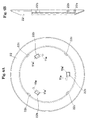
- Figure 4 is a diagram showing a front cover of the ventilating apparatus;
- Figure 4A is a front view and Figure 4B is a partly exploded side view.
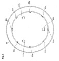
- Figure 5 is a rear view of the front cover.
- Figure 6 is a diagram showing a top panel of the ventilating apparatus;
- Figure 6A is a front view and
- Figure 6B is a partly exploded side view.
- Figure 7 is a diagram showing an attachment member of the ventilating apparatus; Figure 7A is a front view and Figure 7B is a partly exploded side view.
- Figure 8 is a diagram showing a mounting base of the ventilating apparatus; Figure 8A is a front view and Figure 8B is a partly exploded side view.
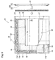
- Figure 9 is a partly exploded side view of the sound deadening cartridge of the ventilating apparatus.
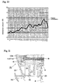
- Figure 10 is a graph showing measurement tests on the sound insulating performance [acoustic transmission loss] of the ventilating apparatus according to the present invention.
- Figure 11 is a central vertical sectional view showing another embodiment of a control plate of the ventilating apparatus.
- Figure 12 is a central vertical sectional view showing another embodiment of the ventilating apparatus according to the present invention.
- Figure 13 is a diagram showing the relationship between a cap cover and a sound deadening cartridge of the ventilating apparatus; Figure 13A is a side view and Figure 13B is a sectional view taken along line XII-XII.
- FIG. 1 to 10 shows an embodiment of the present invention.
- the ventilating apparatus is installed in a ventilating hole 2 drilled in an outer wall 1 of a building to enable natural ventilation.
- the ventilating apparatus comprises a sound deadening cartridge 10 installed in the ventilating hole 2 and a cap cover 20 detachably installed in an interior opening 6 of the ventilating hole 2 and covering the sound deadening cartridge 10 and thus the interior opening 6 of the ventilating hole 2.
- a hood 5 or the like is normally installed at an exterior opening 7 in the outer wall 1 to prevent the entry of rainwater from outdoors 3.
- the cap cover 20 includes at least a mounting base 21 fixed to the ventilating hole 2 and a front cover 22 detachably attached to the mounting base 21.
- An air outlet 24, which blows out into a room 4 introduced external air having passed through the sound deadening cartridge 10, is formed to be open parallel to a wall surface 8.
- the front cover 22 has a ring-like attachment member 25 that can be attached to and detached from the mounting base 21.
- the air outlet 24 is formed by creating a space between the attachment member 25 and the front cover 22.
- the mounting base 21 and the front cover 22 are connected together by installing the attachment member 25, having a pawl, between the mounting base 21 of the cap cover 20 and the front cover 22.
- the air outlet 24, which blows out into the room 4 introduced external air having passed through the sound deadening cartridge 10, is formed between the mounting base 21 and the front cover 22. That is, the front cover 22 is attached to the attaching pawl 26 of the attachment member 25, detachably attached to the mounting base 21, fixed to the outer wall 1.
- a space of a specified size is created between the attachment member 25, integrated with the mounting base 21, and the front cover 22, to constitute the air outlet 24.
- the air outlet 24 facing the ceiling is opened up to 220° including a normally open portion 32 of about 110° when the apparatus is placed to face the ceiling.
- the remaining area of 140° closer to the floor is a normally closed area 34.
- a control plate 30 is placed between the normally closed area 34 and the normally open area 32.
- An adjustment area 33 is set so as to allow the control plate 30 to open and close within the range of about 55° in a lateral direction.
- the normally open portion 32 is placed to face upward, while the normally closed portion 34 is placed to face downward.
- Normally introduced external air is blown out mainly upward around a vertical axis and along the wall. The external air is not blown out toward the residents' feet or the floor.
- the angles of the normally open portion 32, normally closed portion 34, and adjustment area 33 are limited to the above values. Of course, these values can be freely set.
- the control plate 30 is placed in the air outlet 24 and can partly open and close the air outlet 24 to control the amount of external air introduced.
- the control plate 30 is placed between the front cover 22 of the cap cover 20 and the mounting base 21.
- the control plate 30 is fitted into a guide groove 31 formed along edges of the front cover 22 and mounting base 21. The control plate 30 is thus supported so that it can slide through the guide groove 31 along the edges. Even when the control plate 30 is fully closed, the upper normally open portion 32 of the air outlet 24 remains open.
- the mounting base 21 has a cylindrical portion 21a inserted into the interior opening 6 of the ventilating hole 2, drilled in the outer wall 1, and a flange portion 21b extending radially outward from the edge of the opening 6. With the cylindrical portion 21a inserted into the ventilating hole 2, the flange portion 21b is fixed to the wall surface 8 using screws or the like.
- the flange portion 21b of the mounting base 21 is provided with hooks 21c used to detachably fix the attachment member 25, which partitions the air outlet 24.
- four hooks 21c are integrated with the mounting base 21 and arranged at intervals of 90°.
- the attachment member 25 is provided with four L-shaped engagement grooves 25a corresponding to the hooks 21c on the mounting base 21.
- the attachment member 25 is fixedly engaged with the mounting base 21 by inserting each of the hooks 21c into an introducing portion 25a' of the corresponding L-shaped engagement groove 25a so that the hook 21c projects from the front surface of the attachment member 25, and then slightly rotating the attachment member 25. Accordingly, every rotation of the attachment member 25 enables the position where the attachment member 25 is attached to the mounting base 21 to be shifted by 90°. This makes it possible to change the positions of the normally open portion 32 of the air outlet 24 and the control plate 30 and thus the introduced external air blowout position and direction.
- reference numeral 21d denotes a screw hole.
- one or more attaching pawls 26 projecting toward the room 4 are provided on a surface of the attachment member 25 which is opposite to its surface abutting against the mounting base 21.
- Each of the attaching pawls 26 has two step portions 26a that are tapered step by step toward its tip.
- Intermediate rings 27 are fixedly arranged at constant intervals using the step portions 26a as stoppers.
- the intermediate rings 27 function as straightening vanes and serve as barricades that inhibit foreign matter from entering the air outlet 24.
- a dovetail groove 27a is formed in the inner peripheral surface of each of the intermediate rings 27.
- Each of the attaching pawls 26 is fitted into the corresponding groove 27a to allow the plurality of intermediate rings 27 to be fixed at intervals.
- Each of the intermediate ring 27 and the attachment member 25 are positioned using the two step portions 26a of the attaching pawl 26 as stoppers.
- Figure 1 shows the two intermediate rings 27.
- the present invention is not limited to this. It is possible to produce the foreign matter entry preventing effect and the straightening effect provided that at least one intermediate ring 27 is provided.
- each of the holding portions 22a consists of a C-shaped groove and each of the attaching pawls 26 on the attachment member 25 is inserted into the corresponding holding portion 22a.
- the front cover 22 is detachably assembled with the attachment member 25 by inserting each of the holding portions 22a into the tip of the corresponding attaching pawl 26 on the attachment member 25, fixed to the wall surface 8 via the mounting base 21.
- the front cover 22 is provided with hooks 22b projecting from its rear surface.
- the hooks 22b are integrated with the front cover 22.
- Three hooks 22b are provided at intervals of 90°.
- the hooks 22b engage with L-shaped engagement grooves 11a formed in a front surface of a front case 11 of the sound deadening cartridge 10, in the present embodiment, three-L-shaped engagement grooves 11a. That is, the front cover 22 and the sound deadening cartridge 10 are fixedly engaged with each other by inserting each of the hooks 22b into an introducing portion 11a' of the corresponding L-shaped engagement groove 11a in the front case 11 of the sound deadening cartridge 10, and then slightly relatively rotating the sound deadening cartridge 10.
- the sound deadening cartridge 10 is inserted into the ventilating hole 2 through the opening in the mounting base 21.
- each of the holding portions 22a of the front cover 22 is fitted and coupled to the tip of the corresponding attaching pawl 26 on the attachment member 25.
- the front cover 22 and the sound deadening cartridge 10 are fixed to the outer wall 1 via the attachment member 25 and the mounting base 21.
- a guide groove 31 is formed in the opposite surfaces of the front cover 22b and attachment member 25 to movably support the control plate 30, which adjusts the opening of the air outlet 24.
- the control plate 30 constitutes a circular arc having the same curvature as that of contour of the front cover 22b.
- the control plate 30 is slidably supported between the front cover 22b and the attachment member 25 so that its opposite edges are fitted into the guide groove 31.
- the movable range (the amount of opening and closing) of the control plate 30 is determined by the length of the guide groove 31 in the direction in which the air outlet 24 is closed.
- the movable range of the control plate 30 is determined by the abutment against a boundary step 35 in the direction in which the air outlet 24 is opened.
- the control plate 30 can be fixed to an arbitrary position using a frictional force acting on its part fitted into the guide groove 31.
- the air outlet 24 partly has a normally closed area (normally closed portion) 34.
- the normally closed portion 34 extends between the front cover 22b and the attachment member 25.
- the air outlet 24 is closed by providing a bulkhead 29 between the front cover 22b and the attachment member 25 to close the space.
- the bulkhead 29 is placed inside the control plate 30 and integrated with the rear surface of the front cover 22b.
- the boundary step 35 is formed at an intermediate position to prevent movement of the control plate 30, which slides upward.
- a catching portion 36 is provided at each of the opposite ends of the control plate 30 so as to project radially outward. The control plate 30 can be easily opened and closed by catching the user's finger on the catching portion 36.
- the intermediate ring 27 has an outer diameter smaller than those of the front cover 22 and the attachment member 25.
- at least one intermediate ring 27 is placed between the front cover 22 and the attachment member 25 so as to be recessed with respect to them.
- the bulkhead 29 and the control plate 30 are arranged on (around) the intermediate ring 27.
- the intermediate ring 27 consists of a concentric ring and generally has a small diameter. It is sufficient that the intermediate ring 27 can avoid interfering with the control plate 30 at least within the movable range of the control plate 30.
- the cap cover 20 has a top panel 23 that can be attached to and detached from the front cover 22.
- the top panel 23 is composed of a transparent material.
- An exhibit 28 such as a favorite photograph, picture, pattern, wall paper, or pressed flower can be housed between the top panel 23 and the front cover 22 so that a user can enjoy looking it.
- the transparent top panel 23 is not limited to a particular shape provided that it is shaped to form a space in which the exhibit 28 such as a photograph can be housed.
- the top panel 23, including the front cover 22, is shaped like a dome generally bulging forward.
- a method for fixing the transparent top panel 23 to the front cover 22 is not limited to particular means.
- the transparent top panel 23 may be detachably installed on the front cover 22 utilizing its elastic force.
- a plurality of, for example, four projections 23a are provided around the periphery of the transparent top panel 23 as shown in Figure 6.
- the projections 23a are attached to the front cover 22 utilizing the L-shaped engagement grooves 22c, formed in the front cover 22. That is, the projections 23a are fixedly engaged with the L-shaped engagement grooves 22c by abutting and pushing them in the engagement grooves 22c and slightly rotating them in a circumferential direction.
- the front cover 22 and the transparent top panel 23 are fixedly engaged with each other by inserting each of the projections 23a into an introducing portion 22c' of the corresponding L-shaped engagement groove 22c toward the rear surface of the front cover 22 and then slightly rotating the transparent top panel 23.
- the sound deadening cartridge 10 consists of an expanding silencer 18 and sound absorbing materials 19 and 37 which cover an inner surface of the expanding silencer 18 and an external air inlet 15 and which also serve as filters.
- the expanding silencer forming an expandable, resonant space is formed by combining an external cylinder 13 that can be separated into a front case 11 and a rear case 12, with an internal cylinder 14 shorter than the external cylinder 13.
- An exhaust port 16 in communication with the air outlet 24 is opened in a peripheral surface of the front case 11 so as to face in all directions.
- the exhaust port 16 is formed between ribs 11b provided at intervals of 45°.
- the exhaust port 16 has a large opening area and offers a minimum air-flow resistance. That is, the amount of ventilation is not substantially affected because effective opening area is not substantially reduced.
- the rear case 12 of the external cylinder 13 and the internal cylinder 14 are concentrically arranged and connected together by a wall 17.
- the length L1 of the internal cylinder 14 is set about one-fifth of the length L2 of the external cylinder 13 between inner walls.
- the sound absorbing material 19 is bonded to an inner surface of the external cylinder 13 and to an outer surface of the wall 17 including the external air inlet 15 in the internal cylinder 14.
- parts of the sound absorbing materials 37 and 19 which is located in the exhaust port 16 also serve as air filters; the sound absorbing material 37 covering the external air inlet 15 and the sound absorbing material 19 is placed on the inner peripheral surface of the external cylinder 13.
- the detachable pre-filter 38 externally covers the external air inlet 15.
- the pre-filter 38 is detachably installed outside the sound absorbing material 37, which covers the external air inlet 15.
- the pre-filter 38 is composed of, for example, a non-woven fabric filter 39 and a presser ring 40 that holds the periphery of the non-woven fabric filter 39.
- the pre-filter 38 is fixed without using any screws, by fitting the presser ring 40 into a concave portion at an end of the sound deadening cartridge 10 which is closer to the external air inlet.
- the pre-filter 38 is detachably installed.
- the presser ring 40 has four elastic pawls 41 disposed on its circumference; the elastic pawls 41 comprise projections with a small height of about 0.25 mm and can be deformed in an internally radial direction.
- the elastic pawls 41 are utilized to fix the presser ring 40 and to remove it from the cartridge 10.
- the pre-filter 38 is used to capture large contaminants, dust, pollen, and the like, which are entrained in introduced external air, to prevent them from entering the sound deadening cartridge 10. Accordingly, simple replacement of the pre-filter 38 prevents the sound absorbing materials 37 and 19, also serving as air filters, from being clogged. This makes it possible to increase the amount of time before the sound deadening cartridge main body must be replaced with a new one.
- a material for the sound absorbing materials 19 and 37 is not particularly limited. However, it is preferable to use a non-woven fabric consisting of an organic polymer such as polyester or a porous material such as an urethane foam. More preferably, a mixture of an antibacterial, deodorant metal and titanium oxide with antibacterial, deodorant ceramic is attached to in the sound absorbing materials 19 and 37 or the sound absorbing materials 19 and 37 are impregnated with the mixture. In this case, while introduced external air is passing through the sound deadening cartridge, the surface of the sound deadening materials, also serving as filters, capture and kill germs, which are contained in the air and which causes a stench.
- the antibacterial, deodorant ceramic is preferably composed of one or more ceramics selected from a group consisting of for example, SiO 2 -, Al 3 O 3 -, TiO 2 -, ZrO 2 -, and Fe 2 O 3 -based ceramics.
- the antibacterial, deodorant metal is preferably composed of one or more metals selected from gold, silver, and copper.
- the ventilating apparatus according to the present embodiment configured as described above can be constructed as described below.
- the mounting base 21 is inserted into the interior opening 6 of the ventilating hole 2, drilled in the outer wall 1.
- the mounting base 21 is then fixed using screws (not shown) or the like.
- the hooks 22b on the rear surface of the front cover 22 are utilized to fix the cap cover 20 to the mounting base 21 via the attachment member 25; the sound deadening cartridge 10 has been attached to the cap cover 20.
- the cap cover 20 is fixed to the mounting base 21 simply by performing the following operation.
- the introducing portions 25a' of the L-shaped engagement grooves 25a in the attachment member 25 are inserted around the corresponding hooks 21c, projecting from the mounting base 21; the sound deadening cartridge 10 has been inserted into the ventilating hole 2 through the opening in the mounting base 21.
- the cap cover 20 is slightly rotated in the engaging direction.
- the cap cover 20, consisting of the attachment member 25, intermediate ring 27, front cover 22, and control plate 30, is fixed to the mounting base 21 after having been assembled into one member. That is, the intermediate ring 27 and the front cover 22 are sequentially fitted into the attaching pawls 26 of the attachment member 25.
- the control plate 30 is inserted into a predetermined position between the front cover 22 and the attachment member 25. The opposite edges of the control plate 30 are fitted into the guide groove 31. The tips of the attaching pawls 26 of the attachment member 25 are inserted into and coupled to the holding portions 22a of the front cover 22.
- the front cover 22 is fixed to the outer wall 1 via the attachment member 25 and the mounting base 21.
- the sound deadening cartridge 10 is attached to the rear surface of the front cover 22. Accordingly, the sound deadening cartridge 10 is supported in the ventilating hole 2 via the front cover 22.
- the sound deadening cartridge 10 is fixedly attached to the front cover 22 by fitting the hooks 22b into the corresponding L-shaped grooves 11a, and then slightly rotating the sound deadening cartridge 10 on the hooks 22b; the hooks 22b are provided on the rear surface of the front cover 22 and are open in an externally radial direction, and the L-shaped grooves 11a are formed in the front surface of the front case 11. Accordingly, the sound deadening cartridge 10 can be removed from the front cover 22 simply by pulling the sound deadening cartridge 10 while rotating it in a direction opposite to that for fixing with respect to the front cover 22. Consequently, the sound deadening cartridge 10 can be easily replaced with a new one.
- the front surface of the front cover 22 is decorated with a favorite photograph, picture, pressed flower, wallpaper, or the like and is then covered with the transparent top panel 23.
- the transparent top panel 23 is fixed by placing the projections 23a, provided around the periphery, in the corresponding engagement grooves 22c in the front cover 22 and then slightly rotating the top panel 23 in the circumferential direction for engagement. Accordingly, to replace the photograph or the like sandwiched between the front cover 22 and the transparent top panel 23, the top panel 23 has only to be removed by rotating it in the opposite direction.
- the installation of the transparent top panel 23 changes the interior design of the ventilating apparatus. Consequently, it is possible to make an interior atmosphere suitable for the season by adopting a color or design suitable for the season to give a cold or warm feeling. Furthermore, not only the color but also the combination of the transparent top panel 23 and the front cover 22 may be varied.
- the air outlet 24 is formed between the front cover 22 and the attachment member 25, it is possible to provide a large spacing between the front cover 22 and the attachment member 25. Pressure loss can be reduced by increasing the width of the air outlet 24. This improves the natural ventilating capability.
- the ventilating apparatus according to the present embodiment instead of flowing straight, introduced external air collides against the wall of front case of the sound deadening cartridge 10 and then flows into the room while spreading parallel to the wall surface and radially outward (radiantly). Accordingly, the ventilating apparatus according to the present invention comprises a sound insulating function to attenuate the propagation of outdoor noise to the indoor. Therefore, the ventilating apparatus according to the present invention can ventilate not only general homes but also rooms in medical facilities or the like which must be quiet.
- the sound absorbing material 19 may have a dust filtering function. This improves the purity of external air introduced into the room. Moreover, since natural ventilation is based on a difference in pressure between the indoors and the outdoors, external air free from pollen or the like can be introduced by employing a sound absorbing material having a pollen removing function or a separate filter.
- the ventilating apparatus used for the measurement tests is shown in Figure 1.
- the external cylinder 13 had a length L1 of 144 mm, an outer diameter of 136 mm, and an inner diameter of 130 mm.
- the internal cylinder 14 had an inner diameter of 50 mm, an outer diameter of 55 mm, and a length L2 of 104 mm.
- the external air inlet 15 was formed in the internal cylinder 14 at a position 10 mm away from the end of the external cylinder 13.
- the exhaust port 16 in the external cylinder 13 had eight openings each of length 32 mm and angle of aperture 40°.
- the maximum opening of the air outlet 24 and the normally closed area were 220° and 140°, respectively.
- the tests were conducted using a method for displaying and measuring environmental noise in accordance with JIS-Z8731.
- the results of the present tests showed a significant improvement in sound insulation over the entire audible frequency band, particularly in a band of 200 Hz to 3.15 kHz compared to comparative examples 1 and 2.
- a significant sound insulating performance was exhibited at a frequency of 500 Hz to 1 kHz.
- the sound insulating effect can be improved. Further, since the exhaust port 16 is formed almost all along the circumference of the cartridge 10, the amount of ventilation is not substantially affected because the effective opening area is not substantially reduced.
- a photograph or a pressed flower is accommodated below the transparent top panel 23 as a decoration.
- various designs or photographs may be printed directly on the top panel 23 itself to provide top panels 23 with various colors or designs. Then, the interior design may be varied by changing the top panel 23.
- the normally closed portion 34 is placed to face downward.
- the normally open portion 32 is placed to face upward.
- the adjustment area 33 is placed to face in a lateral direction.
- the normally open portion 32 and the adjustment area 33 may be placed to face upward and downward, respectively, with the normally closed portion 34 sandwiched between them so that introduced external air can be blown out downward.
- the normally open portion 32 can be placed in the lower part of the ventilating apparatus of the same structure by removing the attachment member 25 from the mounting base 21, rotating the attachment member through 180°, and then attaching it to the mounting base 21.
- control plate (shutter) 30 may not only slide in the circumferential direction to change the opening of the air outlet 24 but also penetrate the front cover 22 so that it can move toward and away from the wall as shown in Figure 11. In the latter case, the opening can be adjusted between a fully closed state and a fully open state within a specified area.
- a catching portion 36' is provided at a proximal end of the control plate 30 so that the user can utilize the catching portion 36' to move the control plate 30 in and out to adjust the opening of the air outlet 24.
- This embodiment is free from the normally closed portion 34 and is composed only of the normally open portion 32 and the adjustment area 33. However, the normally closed portion 34 may be provided.
- the front cover 22, the intermediate ring 27, and the attachment member 25 are pre-assembled and integrated into one block, which can then be detachably attached to the mounting base 21.
- the present invention is not limited to this. All the parts may be sequentially assembled to and disassembled from the mounting base 21.
- an operation of replacing the sound deadening cartridge 10 is performed by enabling only the front cover 22 and the sound deadening cartridge 10 attached to the front cover 22 to be attached to and detached from the attaching claws 26.
- the front cover 22 is removed from the attaching pawl 26 to take the sound deadening cartridge 10 out of the ventilating hole 2.
- the sound deadening cartridge 10 is replaced with a new one.
- the front cover 22 is then fitted into the attaching pawl 26 to install the sound deadening cartridge 10 in the ventilating hole 2.
- the attachment member 25 may be omitted and the attaching pawls supporting the front cover 22 and intermediate ring 27 may be projected directly from the mounting base 21. Then, the air outlet 24 is formed of a space created between the mounting base 21 and the front cover 22. In this case, an operation of replacing the sound deadening cartridge 10 is performed by enabling only the front cover 22 and the sound deadening cartridge 10 attached to the front cover 22 to be attached to and detached from the mounting base 21.
- the air outlet 24 may be normally open in all directions.
- the air outlet 24, through which introduced external air having passed through the sound deadening cartridge 10 is blown out into the room 4 may be open parallel to the wall surface 8 in all directions (360°) so as to allow the introduced external air to flow out along the wall surface 8.
- the air outlet is always open in any direction regardless of the arrangement of furniture or the like and is thus not substantially closed up. This ensures sufficient natural ventilation.
- the air outlet 24 is formed by connecting the mounting base 21 and the front cover 22 together between the mounting base 21 of the cap cover 20 and the front cover 22 via a second ring panel 25 with a pawl; introduced external air having passed through the sound deadening cartridge 10 is blown out into the room 4 through the air outlet 24.
- One or more intermediate rings 27 function both as barricades inhibiting foreign matter from entering the air outlet 24 and as straightening vanes; the intermediate rings 27 have a simple structure in which they are fixedly arranged at constant intervals between the front cover 22 and the mounting base 21. Therefore, the air outlet 24 has a very simple configuration.
- the remaining part of configuration of the air outlet 24 is basically the same as that in the embodiment shown in Figures 1 to 10 except that it is normally open in all directions.
- the front cover 22, the intermediate ring 27, and the attachment member 25 may be assembled and integrated into one block and then detachably attached to the mounting base 21, as in the case of the ventilating apparatus according to the embodiment shown in Figures 1 to 10.
- the control plate 30 since the control plate 30 is not placed between the front cover 22 and the attachment member 25, the parts may be sequentially assembled to the mounting base 21.
- the attachment member 25 is fixedly caught on the mounting base 21, fixed to the outer wall 1.
- the intermediate ring 27 is sequentially fixedly fitted into the attaching pawls 26 on the attachment member 25.
- the sound deadening cartridge 10 is inserted into the ventilating hole 2 through the opening in the mounting base 21.
- the tips of the attaching pawls 26 of the attachment member 25 are inserted into and coupled to the corresponding holding portions 22a of the front cover 22. This allows the front cover 22 and the sound deadening cartridge 10 to be fixed to the outer wall 1 via the second ring panel 25 and the mounting base 21.
Landscapes
- Engineering & Computer Science (AREA)
- Chemical & Material Sciences (AREA)
- Combustion & Propulsion (AREA)
- Mechanical Engineering (AREA)
- General Engineering & Computer Science (AREA)
- Ventilation (AREA)
Applications Claiming Priority (3)
| Application Number | Priority Date | Filing Date | Title |
|---|---|---|---|
| JP2003118847 | 2003-04-23 | ||
| JP2003271432U JP3100699U (ja) | 2003-09-26 | 2003-09-26 | 換気装置 |
| PCT/JP2004/000240 WO2004094920A1 (fr) | 2003-04-23 | 2004-01-15 | Ventilateur |
Publications (1)
| Publication Number | Publication Date |
|---|---|
| EP1628084A1 true EP1628084A1 (fr) | 2006-02-22 |
Family
ID=34277116
Family Applications (1)
| Application Number | Title | Priority Date | Filing Date |
|---|---|---|---|
| EP04702423A Withdrawn EP1628084A1 (fr) | 2003-04-23 | 2004-01-15 | Ventilateur |
Country Status (5)
| Country | Link |
|---|---|
| US (1) | US20060240763A1 (fr) |
| EP (1) | EP1628084A1 (fr) |
| JP (1) | JP4484820B2 (fr) |
| KR (1) | KR20060008277A (fr) |
| WO (1) | WO2004094920A1 (fr) |
Cited By (12)
| Publication number | Priority date | Publication date | Assignee | Title |
|---|---|---|---|---|
| WO2007006568A1 (fr) * | 2005-07-12 | 2007-01-18 | Berbel Ablufttechnik Gmbh | Caisson de guidage d'air |
| EP2177842A1 (fr) * | 2008-10-16 | 2010-04-21 | EUR.EX S.r.l. | Dispositif d'amortissement du son pour aérations ou pour conduits de prises d'air dans des salles de bâtiments |
| GB2464746A (en) * | 2008-10-24 | 2010-04-28 | Marine Systems Technology Ltd | Noise reduction in ducted air systems |
| ITMC20090133A1 (it) * | 2009-06-04 | 2010-12-05 | Isofom S R L | Cartuccia silenziata per presa d'aria di edifici. |
| ITMI20120925A1 (it) * | 2012-05-28 | 2013-11-29 | Tecnasfalti S R L | Silenziatore acustico di prese d'aria |
| EP2863136A1 (fr) * | 2013-10-15 | 2015-04-22 | LTM GmbH | Couvercle pour des ouvertures dans des parois |
| WO2015122832A1 (fr) * | 2014-02-11 | 2015-08-20 | Lindab Ab | Dispositif de ventilation à vitesse de l'air variable |
| CN107202414A (zh) * | 2017-06-07 | 2017-09-26 | 中车长春轨道客车股份有限公司 | 一种声学混响室专用通风口结构 |
| EP3569948A1 (fr) * | 2018-05-17 | 2019-11-20 | InVENTer GmbH | Dispositif d'aération |
| EP4170255A1 (fr) * | 2021-10-20 | 2023-04-26 | Lindinvent AB | Dispositif compact pour commander un écoulement d'air |
| EP4265971A1 (fr) * | 2022-04-21 | 2023-10-25 | Atlantic Climatisation et Traitement d'Air Industrie | Visière pare-pluie pour systeme de ventilation d'une habitation |
| EP4498009A1 (fr) * | 2023-07-27 | 2025-01-29 | LTG Aktiengesellschaft | Dispositif d'aération doté d'une protection acoustique, agencement |
Families Citing this family (26)
| Publication number | Priority date | Publication date | Assignee | Title |
|---|---|---|---|---|
| KR100839468B1 (ko) * | 2008-01-08 | 2008-06-19 | 주식회사 디아이피 | 진공 쓰레기 수거 시스템의 공기 흡입장치 |
| JP2009243113A (ja) * | 2008-03-31 | 2009-10-22 | Kurabo Ind Ltd | 換気孔の吸音構造 |
| CN102187159B (zh) * | 2008-05-13 | 2014-01-29 | 格雷戈里·S·丹尼尔 | 防余烬及火焰的屋顶通风系统 |
| JP5404146B2 (ja) * | 2009-04-14 | 2014-01-29 | 東芝キヤリア株式会社 | 給気シャッター |
| KR200448247Y1 (ko) * | 2009-10-06 | 2010-03-29 | 주식회사 바이롬 | 흡음체를 구비한 취출구 |
| US8782967B2 (en) | 2010-09-27 | 2014-07-22 | Gregory S. Daniels | Above sheathing ventilation system |
| EP2565548A1 (fr) * | 2011-09-05 | 2013-03-06 | Strabag Ag | Buse de décharge d'air pour aération à haute pression |
| US20160067530A1 (en) * | 2014-09-08 | 2016-03-10 | Walton W. McCarthy | Air gully manifold |
| JP6118485B2 (ja) * | 2015-02-02 | 2017-04-19 | 株式会社シルファー | 換気装置 |
| CN105737315A (zh) * | 2016-02-29 | 2016-07-06 | 青岛海尔空调器有限总公司 | 一种换新风装置及空调器 |
| CN105698362A (zh) * | 2016-02-29 | 2016-06-22 | 青岛海尔空调器有限总公司 | 一种换新风装置及空调器 |
| CN105571043A (zh) * | 2016-02-29 | 2016-05-11 | 青岛海尔空调器有限总公司 | 一种换新风装置及空调器 |
| CN105737290A (zh) * | 2016-02-29 | 2016-07-06 | 青岛海尔空调器有限总公司 | 一种换新风装置及空调器 |
| JPWO2018150972A1 (ja) * | 2017-02-17 | 2019-12-19 | 富士フイルム株式会社 | 防音構造体 |
| JP6401813B2 (ja) * | 2017-03-22 | 2018-10-10 | 株式会社シルファー | 換気装置 |
| JP6672390B2 (ja) * | 2017-07-05 | 2020-03-25 | 富士フイルム株式会社 | 消音システム |
| WO2019009338A1 (fr) * | 2017-07-05 | 2019-01-10 | 富士フイルム株式会社 | Système insonorisant |
| KR102432767B1 (ko) * | 2017-09-18 | 2022-08-16 | 주식회사 아모그린텍 | 미세먼지 제거가 가능한 공기정화 시스템 |
| JP6673885B2 (ja) * | 2017-09-21 | 2020-03-25 | 富士フイルム株式会社 | 消音システム |
| JP6691521B2 (ja) * | 2017-09-21 | 2020-04-28 | 富士フイルム株式会社 | 消音システム |
| CN109990424B (zh) * | 2017-12-30 | 2024-05-03 | 上海神洁环保科技股份有限公司 | 一种新型组合式防水型消声通风系统 |
| WO2019212528A1 (fr) * | 2018-05-01 | 2019-11-07 | Volpe Miles | Évent télescopique |
| JP7292129B2 (ja) * | 2019-06-28 | 2023-06-16 | 東洋アルミエコープロダクツ株式会社 | 通気口用カバー |
| CN113091185B (zh) * | 2020-01-07 | 2025-08-05 | 森德(中国)暖通设备有限公司 | 一种换气净化装置 |
| JP7691341B2 (ja) * | 2021-10-28 | 2025-06-11 | 三井住友建設株式会社 | 室外音取り入れ装置 |
| CN114396389B (zh) * | 2021-12-31 | 2022-11-18 | 英飞同仁风机股份有限公司 | 一种上吹式消音型屋顶风机 |
Family Cites Families (8)
| Publication number | Priority date | Publication date | Assignee | Title |
|---|---|---|---|---|
| JPS58194431U (ja) * | 1982-06-21 | 1983-12-24 | 大成建設株式会社 | 消音機能を有する換気装置 |
| JPS6028331U (ja) * | 1983-08-03 | 1985-02-26 | 株式会社大林組 | 換気装置の消音構造 |
| JPS61175831U (fr) * | 1985-04-23 | 1986-11-01 | ||
| JPH055378Y2 (fr) * | 1988-09-29 | 1993-02-12 | ||
| JPH07260243A (ja) * | 1994-02-04 | 1995-10-13 | Sekisui Chem Co Ltd | 給気レジスタ |
| JPH11237090A (ja) * | 1998-02-23 | 1999-08-31 | Sanbekku Kk | ベントキャップ |
| JP3693521B2 (ja) * | 1999-04-21 | 2005-09-07 | 松下エコシステムズ株式会社 | 消音型給気口 |
| JP4420361B2 (ja) * | 1999-04-23 | 2010-02-24 | 株式会社長谷工コーポレーション | 換気レジスター |
-
2004
- 2004-01-15 WO PCT/JP2004/000240 patent/WO2004094920A1/fr not_active Ceased
- 2004-01-15 US US10/554,180 patent/US20060240763A1/en not_active Abandoned
- 2004-01-15 KR KR1020057012061A patent/KR20060008277A/ko not_active Withdrawn
- 2004-01-15 JP JP2005505683A patent/JP4484820B2/ja not_active Expired - Fee Related
- 2004-01-15 EP EP04702423A patent/EP1628084A1/fr not_active Withdrawn
Non-Patent Citations (1)
| Title |
|---|
| See references of WO2004094920A1 * |
Cited By (17)
| Publication number | Priority date | Publication date | Assignee | Title |
|---|---|---|---|---|
| WO2007006568A1 (fr) * | 2005-07-12 | 2007-01-18 | Berbel Ablufttechnik Gmbh | Caisson de guidage d'air |
| EP2177842A1 (fr) * | 2008-10-16 | 2010-04-21 | EUR.EX S.r.l. | Dispositif d'amortissement du son pour aérations ou pour conduits de prises d'air dans des salles de bâtiments |
| GB2464746A (en) * | 2008-10-24 | 2010-04-28 | Marine Systems Technology Ltd | Noise reduction in ducted air systems |
| ITMC20090133A1 (it) * | 2009-06-04 | 2010-12-05 | Isofom S R L | Cartuccia silenziata per presa d'aria di edifici. |
| ITMI20120925A1 (it) * | 2012-05-28 | 2013-11-29 | Tecnasfalti S R L | Silenziatore acustico di prese d'aria |
| EP2863136A1 (fr) * | 2013-10-15 | 2015-04-22 | LTM GmbH | Couvercle pour des ouvertures dans des parois |
| US10443887B2 (en) | 2014-02-11 | 2019-10-15 | Lindab Ab | Ventilation device with varying air velocity |
| WO2015122832A1 (fr) * | 2014-02-11 | 2015-08-20 | Lindab Ab | Dispositif de ventilation à vitesse de l'air variable |
| WO2015122831A1 (fr) * | 2014-02-11 | 2015-08-20 | Lindab Ab | Dispositif de ventilation avec génération réduite de bruit |
| SE541076C2 (sv) * | 2014-02-11 | 2019-03-26 | Lindab Ab | Ventilationsdon med ljuddämpning. |
| CN107202414A (zh) * | 2017-06-07 | 2017-09-26 | 中车长春轨道客车股份有限公司 | 一种声学混响室专用通风口结构 |
| EP3569948A1 (fr) * | 2018-05-17 | 2019-11-20 | InVENTer GmbH | Dispositif d'aération |
| EP4170255A1 (fr) * | 2021-10-20 | 2023-04-26 | Lindinvent AB | Dispositif compact pour commander un écoulement d'air |
| WO2023066806A1 (fr) * | 2021-10-20 | 2023-04-27 | Lindinvent Ab | Dispositif compact pour la régulation d'un courant d'air |
| EP4265971A1 (fr) * | 2022-04-21 | 2023-10-25 | Atlantic Climatisation et Traitement d'Air Industrie | Visière pare-pluie pour systeme de ventilation d'une habitation |
| FR3134877A1 (fr) * | 2022-04-21 | 2023-10-27 | Atlantic Climatisation et Traitement d’Air Industrie | Visière pare-pluie pour système de ventilation d’une habitation |
| EP4498009A1 (fr) * | 2023-07-27 | 2025-01-29 | LTG Aktiengesellschaft | Dispositif d'aération doté d'une protection acoustique, agencement |
Also Published As
| Publication number | Publication date |
|---|---|
| WO2004094920A8 (fr) | 2006-02-23 |
| HK1092205A1 (zh) | 2007-02-02 |
| JP4484820B2 (ja) | 2010-06-16 |
| KR20060008277A (ko) | 2006-01-26 |
| US20060240763A1 (en) | 2006-10-26 |
| JPWO2004094920A1 (ja) | 2006-07-13 |
| WO2004094920A1 (fr) | 2004-11-04 |
Similar Documents
| Publication | Publication Date | Title |
|---|---|---|
| EP1628084A1 (fr) | Ventilateur | |
| US9011565B2 (en) | Attachable air filter for an air vent register | |
| US5643081A (en) | Vent screen and vent apparatus | |
| KR102087826B1 (ko) | 창문 설치용 환기장치 | |
| US20200103138A1 (en) | System and Method for HVAC Register Filtration | |
| CN113123537A (zh) | 具有邻近屋顶窗户安装的通风单元的屋顶窗户系统及其提供和改装方法、包括其的屋顶结构 | |
| US20060085898A1 (en) | Toilet ventilation system | |
| US6584620B1 (en) | Detachable toilet ventilation system | |
| CN100370186C (zh) | 带消音盒的换气结构 | |
| JP3100699U (ja) | 換気装置 | |
| JP3385862B2 (ja) | 換気扇 | |
| KR20210074516A (ko) | 탄성시트체를 가진 역풍방지장치 | |
| KR20220000836U (ko) | 급기 레지스터 | |
| KR200399564Y1 (ko) | 공조 시스템의 공기 디퓨져 | |
| HK1092205B (en) | Ventilating structure with sound-deadening cartridge | |
| CN108979467A (zh) | 一种具有通风功能的房门 | |
| TWM320594U (en) | Ventilation apparatus | |
| JP4853801B2 (ja) | 給排気が同時に作動する自然換気装置 | |
| JP3898282B2 (ja) | 換気口 | |
| JPH0320418Y2 (fr) | ||
| JP3118090U (ja) | 天井床下換気口 | |
| JP2010203707A (ja) | 換気装置 | |
| JP2005226949A (ja) | フィルター付き換気グリル | |
| CN2416174Y (zh) | 通风管 | |
| KR200418516Y1 (ko) | 건축물용 환기장치 |
Legal Events
| Date | Code | Title | Description |
|---|---|---|---|
| PUAI | Public reference made under article 153(3) epc to a published international application that has entered the european phase |
Free format text: ORIGINAL CODE: 0009012 |
|
| 17P | Request for examination filed |
Effective date: 20051117 |
|
| AK | Designated contracting states |
Kind code of ref document: A1 Designated state(s): AT BE BG CH CY CZ DE DK EE ES FI FR GB GR HU IE IT LI LU MC NL PT RO SE SI SK TR |
|
| STAA | Information on the status of an ep patent application or granted ep patent |
Free format text: STATUS: THE APPLICATION HAS BEEN WITHDRAWN |
|
| 18W | Application withdrawn |
Effective date: 20060619 |