EP1628109A2 - Dispositif de cryostat - Google Patents
Dispositif de cryostat Download PDFInfo
- Publication number
- EP1628109A2 EP1628109A2 EP05016143A EP05016143A EP1628109A2 EP 1628109 A2 EP1628109 A2 EP 1628109A2 EP 05016143 A EP05016143 A EP 05016143A EP 05016143 A EP05016143 A EP 05016143A EP 1628109 A2 EP1628109 A2 EP 1628109A2
- Authority
- EP
- European Patent Office
- Prior art keywords
- arrangement according
- cold
- helium
- neck tube
- cryostat arrangement
- Prior art date
- Legal status (The legal status is an assumption and is not a legal conclusion. Google has not performed a legal analysis and makes no representation as to the accuracy of the status listed.)
- Granted
Links
Images


Classifications
-
- F—MECHANICAL ENGINEERING; LIGHTING; HEATING; WEAPONS; BLASTING
- F25—REFRIGERATION OR COOLING; COMBINED HEATING AND REFRIGERATION SYSTEMS; HEAT PUMP SYSTEMS; MANUFACTURE OR STORAGE OF ICE; LIQUEFACTION SOLIDIFICATION OF GASES
- F25D—REFRIGERATORS; COLD ROOMS; ICE-BOXES; COOLING OR FREEZING APPARATUS NOT OTHERWISE PROVIDED FOR
- F25D19/00—Arrangement or mounting of refrigeration units with respect to devices or objects to be refrigerated, e.g. infrared detectors
-
- F—MECHANICAL ENGINEERING; LIGHTING; HEATING; WEAPONS; BLASTING
- F25—REFRIGERATION OR COOLING; COMBINED HEATING AND REFRIGERATION SYSTEMS; HEAT PUMP SYSTEMS; MANUFACTURE OR STORAGE OF ICE; LIQUEFACTION SOLIDIFICATION OF GASES
- F25B—REFRIGERATION MACHINES, PLANTS OR SYSTEMS; COMBINED HEATING AND REFRIGERATION SYSTEMS; HEAT PUMP SYSTEMS
- F25B9/00—Compression machines, plants or systems, in which the refrigerant is air or other gas of low boiling point
- F25B9/14—Compression machines, plants or systems, in which the refrigerant is air or other gas of low boiling point characterised by the cycle used, e.g. Stirling cycle
- F25B9/145—Compression machines, plants or systems, in which the refrigerant is air or other gas of low boiling point characterised by the cycle used, e.g. Stirling cycle pulse-tube cycle
-
- F—MECHANICAL ENGINEERING; LIGHTING; HEATING; WEAPONS; BLASTING
- F25—REFRIGERATION OR COOLING; COMBINED HEATING AND REFRIGERATION SYSTEMS; HEAT PUMP SYSTEMS; MANUFACTURE OR STORAGE OF ICE; LIQUEFACTION SOLIDIFICATION OF GASES
- F25B—REFRIGERATION MACHINES, PLANTS OR SYSTEMS; COMBINED HEATING AND REFRIGERATION SYSTEMS; HEAT PUMP SYSTEMS
- F25B2309/00—Gas cycle refrigeration machines
- F25B2309/14—Compression machines, plants or systems characterised by the cycle used
- F25B2309/1408—Pulse-tube cycles with pulse tube having U-turn or L-turn type geometrical arrangements
-
- F—MECHANICAL ENGINEERING; LIGHTING; HEATING; WEAPONS; BLASTING
- F25—REFRIGERATION OR COOLING; COMBINED HEATING AND REFRIGERATION SYSTEMS; HEAT PUMP SYSTEMS; MANUFACTURE OR STORAGE OF ICE; LIQUEFACTION SOLIDIFICATION OF GASES
- F25B—REFRIGERATION MACHINES, PLANTS OR SYSTEMS; COMBINED HEATING AND REFRIGERATION SYSTEMS; HEAT PUMP SYSTEMS
- F25B2400/00—Component parts or details not otherwise provided for in this subclass
- F25B2400/17—Re-condensers
-
- F—MECHANICAL ENGINEERING; LIGHTING; HEATING; WEAPONS; BLASTING
- F25—REFRIGERATION OR COOLING; COMBINED HEATING AND REFRIGERATION SYSTEMS; HEAT PUMP SYSTEMS; MANUFACTURE OR STORAGE OF ICE; LIQUEFACTION SOLIDIFICATION OF GASES
- F25B—REFRIGERATION MACHINES, PLANTS OR SYSTEMS; COMBINED HEATING AND REFRIGERATION SYSTEMS; HEAT PUMP SYSTEMS
- F25B9/00—Compression machines, plants or systems, in which the refrigerant is air or other gas of low boiling point
- F25B9/10—Compression machines, plants or systems, in which the refrigerant is air or other gas of low boiling point with several cooling stages
-
- F—MECHANICAL ENGINEERING; LIGHTING; HEATING; WEAPONS; BLASTING
- F25—REFRIGERATION OR COOLING; COMBINED HEATING AND REFRIGERATION SYSTEMS; HEAT PUMP SYSTEMS; MANUFACTURE OR STORAGE OF ICE; LIQUEFACTION SOLIDIFICATION OF GASES
- F25D—REFRIGERATORS; COLD ROOMS; ICE-BOXES; COOLING OR FREEZING APPARATUS NOT OTHERWISE PROVIDED FOR
- F25D19/00—Arrangement or mounting of refrigeration units with respect to devices or objects to be refrigerated, e.g. infrared detectors
- F25D19/006—Thermal coupling structure or interface
Definitions
- the invention relates to a Kryostatan extract for storing liquid helium with an outer shell and a built-in helium container, wherein the helium container is connected to at least two suspension tubes with the outer shell, wherein the helium container further includes a neck tube, the upper warm end with the jacket and the lower cold end is connected to the helium container and in which a multi-stage cold head of a cryocooler is installed, wherein the outer shell, the helium container, the suspension tubes and the neck tube define an evacuated space, and wherein the helium container is further surrounded by at least one radiation shield, which with both the hanger ears and thermally conductively connected to the neck tube of the helium container.
- the example two-stage cold head of the cryocooler is usually installed in a separate vacuum space (as described for example in US5613367) or directly into the vacuum space of the cryostat (as described for example in US5563566) so that the first cold stage of the cold head fixed with a radiation shield and the second cold stage be connected via a fixed, rigid or flexible, thermal bridge or directly to the helium container thermally conductive.
- a disadvantage is that the connection from the second cold stage to the helium tank has a thermal resistance.
- One way to avoid this thermal resistance is to insert the cold head into a neck tube which connects the outer vacuum envelope of the cryostat to the helium vessel and is correspondingly filled with helium gas, as described, for example, in document US2002 / 0002830.
- the first cold stage of the two-stage cold head is again solidly contacted with a radiation shield, the second cold stage hangs freely in the helium atmosphere and liquefies directly evaporated helium.
- the helium vessel is usually connected to the outer vacuum envelope on at least two thin-walled hanger tubes.
- the helium container with the superconducting magnet is thus mechanically fixed, on the other hand, the suspension tubes provide access to the magnet, as it may, for. B. when loading is necessary and also serve the refilling of liquid helium.
- the loss of gas is also dissipated via the suspension tubes, whereby the suspension tubes are cooled again and ideally the heat input through the pipe wall is completely compensated.
- the object of the present invention is, therefore, the heat input via the suspension tubes of an actively cooled with a cryocooler Kryostatanssen, especially a shrinkage device containing a superconducting magnet assembly to reduce or completely eliminate and thus allow the use of a lower performance cryocooler.
- This object is achieved in that between the warm ends of the suspension tubes and the neck tube, a direct connection exists, can flow through the helium gas.
- a gas flow is formed by itself, which is excited and maintained by the suction effect at the cold end of the cold head.
- the vaporized gas thus cools the wall of the tubing tubes ideally again so far that the heat input to the helium container disappears through the tubing tubes, heats up and exits at about room temperature from the tubing ears and at room temperature flange of the cold head into the neck tube.
- the gas from the various suspension tubes is preferably collected in a conduit and then routed to the neck tube. As a result of the downward flow in the neck tube, the gas is cooled at the tubes of the cold head or at the neck tube and finally liquefied at the second cold stage of the cold head.
- the cycle is hereby closed.
- the suction that maintains the flow is due, among other things, to the phase change from gaseous to liquid in the second stage of the cold.
- the performance of the cryocooler decreases slightly, but the gain due to the lower heat input is greater than the loss of cooling capacity.
- a less powerful cryocooler can be used as in the case without circulation flow.
- the cold head of the cryocooler is constructed in multiple stages.
- very low temperatures in particular temperatures in the range of or less than 4K can be realized.
- cryocooler is a pulse tube cooler, since pulse tube coolers are operated with particularly low vibration can be. Pulse tube coolers are also very reliable and low maintenance. However, it is also possible in principle to use other cryocoolers, such as Gifford-McMahon coolers.
- helium can be liquefied at a temperature of 4.2 K or at a lower temperature, since this offers a multitude of possible uses in the lowest temperature range.
- the helium vaporizing within the cryostat is liquefied at the freezing stage in the neck tube and drips back into the helium container.
- the helium loss and the refilling operations can be reduced or can be achieved at sufficiently large cooling capacity of the radiator, a loss-free operation.
- the tubes of the cold head are surrounded above the first cold stage and possibly also in the region of further cold stages with a heat insulation.
- an undesirable heat input from the neck tube into the tubes of the cold head can be approximately avoided or at least reduced.
- the tubes above the first cold stage of the cold head have temperatures between room temperature and temperature of the first cold stage.
- a preferred embodiment of the cryostat arrangement provides that there is a gap or channel between the heat insulation and the neck tube wall, through which gas can flow, so that the gas can come in sufficiently good thermal contact with the tube wall.
- the neck tube does not have to assume any mechanical support function, it is advantageous if the neck tube is of thin-walled construction and / or constructed in the form of a bellows, each of a material having poor thermal conductivity. In this way, the heat input into the helium tank is small. At the same time, the vibration transmission through the neck tube is minimized.
- a, preferably electrical, heating is provided in or in contact with the helium container. At an excess power
- the pressure in the helium container can be kept above the ambient pressure and constant in the cryocooler.
- the performance of the radiator is regulated by its operating frequency and / or the amount of working gas in the radiator.
- one or more cold stages of the cold head are thermally conductively connected to one or more radiation shields.
- the radiation shield (s) can then be cooled directly by the cold head.
- the or one of the radiation shields contains a container with liquid nitrogen, with which the cold head is thermally conductively connected, wherein the cold head of the cryocooler at least partially liquefies the nitrogen after evaporation.
- the liquefaction of the nitrogen is due to the thermal connection of the radiation shield to the cold head of the cryocooler.
- the radiation shield is not cooled directly by the cooler, but indirectly, via the evaporating nitrogen.
- a, preferably electrical, heating is provided in or in contact with the nitrogen container in order to maintain the pressure in the nitrogen container above the ambient pressure and constant at an excess power of the cryocooler.
- a valve for controlling the gas flow is provided in the connecting line between suspension tubes and neck tube.
- the gas flow can be throttled when z. B. the suction effect on the cold head is so large that the gas flow is greater than it would be sufficient for the optimal cooling of the suspension tubes.
- Another advantageous aspect includes that in the connecting line between suspension tubes and neck tube a controllable circulation pump is provided.
- the cooling flow can actively adjust.
- cryostat arrangement contains a superconducting magnet arrangement, in particular if the superconducting magnet arrangement is part of an apparatus for nuclear magnetic resonance, in particular magnetic resonance imaging (MRI) or magnetic resonance spectroscopy (NMR).
- MRI magnetic resonance imaging
- NMR magnetic resonance spectroscopy
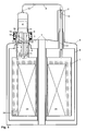
- FIG. 1 shows a schematic representation of a cryostat arrangement according to the invention with a helium container 1 , which is connected to at least two suspension tubes 2 with an outer jacket 3 .
- the helium container 1 is surrounded by a radiation shield 4 and further comprises a neck tube 5 , which houses the cold head 6 of a cryocooler. Since the neck tube 5 only as a partition to an evacuated space 7 of the outer shell 3 and does not have to carry the weight of the helium container 1, it can be designed so that the heat input and the vibration transmission can be minimized. This can be achieved advantageously with the use of bellows.
- the weight of the helium container 1 and a superconducting magnet arrangement 26 arranged in the helium container is carried by the suspension tubes 2, which are connected via a line 8 to the warm end 9 of the neck tube 5. It forms from itself a gas flow 10 , which is excited and maintained by the suction effect at the cold end 11 of the cold head 6.
- the vaporized helium thus cools the wall 12 of the suspension tubes 2, ideally so far that the heat input through the suspension tubes 2 disappears onto the helium vessel 1, heats up and exits the suspension tubes 2 at about room temperature and at a room temperature flange 13 of the cold head 6 again in the neck tube 5 a.
- the gas is cooled at the tubes 14 of the cold head 6 or the neck tube 5 and finally liquefied at the second cold stage 15 of the cold head 6.
- the cycle is hereby closed.
- the performance of the cryocooler decreases slightly, but the gain due to the lower heat input is greater than the loss of cooling capacity.
- a less powerful cryocooler can thus be used than in the case without circulation flow. It is advantageous if the partial flows of the various suspension tubes 2 are combined in a line 8.
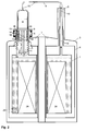
- FIG. 2 shows a heat insulation 16 between the room temperature flange 13 and the first cold stage 17 of the two-stage cold head 6.
- a heat insulation 16 can also be provided around the tubes of further cold stages. It is only important that between the heat insulation 16 and the neck tube wall 18, a sufficiently large gap 19 is present, so that the gas with the neck tube wall 18 in good enough thermal contact can occur.
- the neck tube wall 18 is not cooled in the proposed invention by a guided gas stream to the warm end. As already mentioned above, however, the contribution of the heat input via the neck tube wall 18 for the given case is rather small compared to the total heat input.
- the radiation shield 4 - as in a non-actively cooled system (ie without cryocooler) - is not cooled directly, but with evaporating nitrogen, as shown in Fig. 3 .
- the first cold stage 17 of the cold head 6 of the cryocooler must be thermally conductively connected to a nitrogen container 20 , so that nitrogen vaporized on the cold contact surface 21 can be liquefied again.
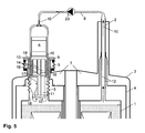
- a flow impedance such as a valve 22
- the cooling flow could be actively regulated (see Fig. 5 ).
- Valve 22 or pump 23 can also be installed together in the connecting line 8.
- the partial flows of the suspension tubes 2 are first combined in a connecting line 8, before a valve 22 or a pump 23 are integrated.
- the cryostat arrangement according to the invention is particularly suitable for cooling a magnet arrangement 26 which is part of an apparatus for nuclear magnetic resonance, in particular magnetic resonance imaging (MRI) or magnetic resonance spectroscopy (NMR).
- MRI magnetic resonance imaging
- NMR magnetic resonance spectroscopy
- cryostat arrangement it is possible, in particular the heat input via the suspension tubes of an active, cooled with a cryocooler, high-resolution NMR magnetic system significantly reduce and thus to use a lower-performance cryocooler.
Landscapes
- Engineering & Computer Science (AREA)
- Physics & Mathematics (AREA)
- Mechanical Engineering (AREA)
- Thermal Sciences (AREA)
- General Engineering & Computer Science (AREA)
- Chemical & Material Sciences (AREA)
- Combustion & Propulsion (AREA)
- Containers, Films, And Cooling For Superconductive Devices (AREA)
- Magnetic Resonance Imaging Apparatus (AREA)
- Filling Or Discharging Of Gas Storage Vessels (AREA)
Applications Claiming Priority (1)
| Application Number | Priority Date | Filing Date | Title |
|---|---|---|---|
| DE102004037172A DE102004037172B4 (de) | 2004-07-30 | 2004-07-30 | Kryostatanordnung |
Publications (3)
| Publication Number | Publication Date |
|---|---|
| EP1628109A2 true EP1628109A2 (fr) | 2006-02-22 |
| EP1628109A3 EP1628109A3 (fr) | 2009-03-25 |
| EP1628109B1 EP1628109B1 (fr) | 2012-06-13 |
Family
ID=35457012
Family Applications (1)
| Application Number | Title | Priority Date | Filing Date |
|---|---|---|---|
| EP05016143A Ceased EP1628109B1 (fr) | 2004-07-30 | 2005-07-26 | Dispositif de cryostat |
Country Status (4)
| Country | Link |
|---|---|
| US (1) | US20060021355A1 (fr) |
| EP (1) | EP1628109B1 (fr) |
| JP (1) | JP3996935B2 (fr) |
| DE (1) | DE102004037172B4 (fr) |
Cited By (2)
| Publication number | Priority date | Publication date | Assignee | Title |
|---|---|---|---|---|
| WO2011112987A3 (fr) * | 2010-03-11 | 2012-11-08 | Quantum Design, Inc. | Procédé et appareil de régulation de la température dans un cryostat refroidi par cryogénisation utilisant du gaz statique et en déplacement |
| EP2584286A4 (fr) * | 2010-06-16 | 2015-08-26 | Kobe Steel Ltd | Dispositif de re-condensation et dispositif d'analyse rmn qui en est equipe |
Families Citing this family (36)
| Publication number | Priority date | Publication date | Assignee | Title |
|---|---|---|---|---|
| GB0424725D0 (en) * | 2004-11-09 | 2004-12-08 | Oxford Instr Superconductivity | Cryostat assembly |
| JP5833284B2 (ja) * | 2006-03-17 | 2015-12-16 | シーメンス ピーエルシー | 冷却装置 |
| US8375742B2 (en) * | 2007-08-21 | 2013-02-19 | Cryomech, Inc. | Reliquifier and recondenser with vacuum insulated sleeve and liquid transfer tube |
| US20110127273A1 (en) * | 2007-12-11 | 2011-06-02 | TOKITAE LLC, a limited liability company of the State of Delaware | Temperature-stabilized storage systems including storage structures configured for interchangeable storage of modular units |
| US20120085070A1 (en) * | 2007-12-11 | 2012-04-12 | TOKITAE LLC, a limited liability company of the State of Delaware | Establishment and maintenance of low gas pressure within interior spaces of temperature-stabilized storage systems |
| US20090145912A1 (en) * | 2007-12-11 | 2009-06-11 | Searete Llc, A Limited Liability Corporation Of The State Of Delaware | Temperature-stabilized storage containers |
| US8215835B2 (en) | 2007-12-11 | 2012-07-10 | Tokitae Llc | Temperature-stabilized medicinal storage systems |
| US9140476B2 (en) | 2007-12-11 | 2015-09-22 | Tokitae Llc | Temperature-controlled storage systems |
| US8603598B2 (en) | 2008-07-23 | 2013-12-10 | Tokitae Llc | Multi-layer insulation composite material having at least one thermally-reflective layer with through openings, storage container using the same, and related methods |
| US8485387B2 (en) | 2008-05-13 | 2013-07-16 | Tokitae Llc | Storage container including multi-layer insulation composite material having bandgap material |
| US8215518B2 (en) * | 2007-12-11 | 2012-07-10 | Tokitae Llc | Temperature-stabilized storage containers with directed access |
| US8069680B2 (en) | 2007-12-11 | 2011-12-06 | Tokitae Llc | Methods of manufacturing temperature-stabilized storage containers |
| US8377030B2 (en) | 2007-12-11 | 2013-02-19 | Tokitae Llc | Temperature-stabilized storage containers for medicinals |
| US8211516B2 (en) * | 2008-05-13 | 2012-07-03 | Tokitae Llc | Multi-layer insulation composite material including bandgap material, storage container using same, and related methods |
| US9174791B2 (en) * | 2007-12-11 | 2015-11-03 | Tokitae Llc | Temperature-stabilized storage systems |
| US8887944B2 (en) | 2007-12-11 | 2014-11-18 | Tokitae Llc | Temperature-stabilized storage systems configured for storage and stabilization of modular units |
| US9205969B2 (en) * | 2007-12-11 | 2015-12-08 | Tokitae Llc | Temperature-stabilized storage systems |
| US9372016B2 (en) | 2013-05-31 | 2016-06-21 | Tokitae Llc | Temperature-stabilized storage systems with regulated cooling |
| US9447995B2 (en) | 2010-02-08 | 2016-09-20 | Tokitac LLC | Temperature-stabilized storage systems with integral regulated cooling |
| US20120167598A1 (en) * | 2010-09-14 | 2012-07-05 | Quantum Design, Inc. | Vacuum isolated multi-well zero loss helium dewar |
| DE102011078608B4 (de) | 2011-07-04 | 2023-06-22 | Bruker Switzerland Ag | Kryostatanordnung |
| CN103077797B (zh) * | 2013-01-06 | 2016-03-30 | 中国科学院电工研究所 | 用于头部成像的超导磁体系统 |
| JP5969944B2 (ja) * | 2013-03-27 | 2016-08-17 | ジャパンスーパーコンダクタテクノロジー株式会社 | クライオスタット |
| DE102015212314B3 (de) | 2015-07-01 | 2016-10-20 | Bruker Biospin Gmbh | Kryostat mit aktiver Halsrohrkühlung durch ein zweites Kryogen |
| JP6626816B2 (ja) * | 2016-11-24 | 2019-12-25 | ジャパンスーパーコンダクタテクノロジー株式会社 | 超電導コイルの予冷方法及び超電導マグネット装置 |
| DE102017217930A1 (de) * | 2017-10-09 | 2019-04-11 | Bruker Biospin Ag | Magnetanordnung mit Kryostat und Magnetspulensystem, mit Kältespeichern an den Stromzuführungen |
| CN110486980B (zh) * | 2019-08-29 | 2021-08-24 | 上海理工大学 | 微通道节流制冷器 |
| CN110486972B (zh) * | 2019-08-29 | 2021-08-24 | 上海理工大学 | 多级两侧预冷叠层交错微通道节流换热制冷器 |
| CN110486973B (zh) * | 2019-08-29 | 2021-08-24 | 上海理工大学 | 具有中间入口的多级预冷微通道节流换热制冷器 |
| CN110486970B (zh) * | 2019-08-29 | 2021-08-24 | 上海理工大学 | 多级单侧预冷的叠层微通道节流换热制冷器 |
| CN110486971B (zh) * | 2019-08-29 | 2021-08-24 | 上海理工大学 | 波浪形叠层微通道制冷器 |
| CN110486974B (zh) * | 2019-08-29 | 2021-08-24 | 上海理工大学 | 具有中间入口的二级叠层交错微通道节流换热制冷器 |
| KR102142312B1 (ko) * | 2019-12-27 | 2020-08-07 | 한국기초과학지원연구원 | 헬륨 가스 액화기 및 헬륨 가스 액화 방법 |
| DE102020201522A1 (de) | 2020-02-07 | 2021-08-12 | Bruker Switzerland Ag | NMR-Messanordnung mit kalter Bohrung des Kryostaten |
| FR3118141B1 (fr) * | 2020-12-18 | 2023-02-24 | Air Liquide | Dispositif et procédé de réfrigération à dilution |
| CN117128442B (zh) * | 2023-08-07 | 2024-05-17 | 北京航天试验技术研究所 | 一种恒温恒压低温杜瓦、系统及其方法 |
Citations (10)
| Publication number | Priority date | Publication date | Assignee | Title |
|---|---|---|---|---|
| US5563566A (en) | 1995-11-13 | 1996-10-08 | General Electric Company | Cryogen-cooled open MRI superconductive magnet |
| US5613367A (en) | 1995-12-28 | 1997-03-25 | General Electric Company | Cryogen recondensing superconducting magnet |
| US5782095A (en) | 1997-09-18 | 1998-07-21 | General Electric Company | Cryogen recondensing superconducting magnet |
| EP0905524A1 (fr) | 1997-09-30 | 1999-03-31 | Oxford Magnet Technology Limited | Agencement d'aimants pour la RMN avec un col logeant un cryogénérateurr du type à tube pulsé |
| EP0905436A2 (fr) | 1997-09-30 | 1999-03-31 | Oxford Magnet Technology Limited | Moyens portants pour RMN systèmes de cryostats |
| US5966944A (en) | 1997-04-09 | 1999-10-19 | Aisin Seiki Kabushiki Kaisha | Superconducting magnet system outfitted with cooling apparatus |
| US20020002830A1 (en) | 2000-07-08 | 2002-01-10 | Bruker Analytik Gmbh | Circulating cryostat |
| WO2003036207A2 (fr) | 2001-10-19 | 2003-05-01 | Oxford Magnet Technology Ltd. | Gaine pour refrigerateur a tube pulse |
| WO2003036190A1 (fr) | 2001-10-19 | 2003-05-01 | Oxford Magnet Technology Ltd. | Refrigerateur a tube pulse comportant une gaine d'isolation |
| US20030230089A1 (en) | 2002-06-14 | 2003-12-18 | Bruker Biospin Gmbh | Cryostat configuration with improved properties |
Family Cites Families (5)
| Publication number | Priority date | Publication date | Assignee | Title |
|---|---|---|---|---|
| DE4106135A1 (de) * | 1991-02-27 | 1992-09-03 | Spectrospin Ag | Kryomagnetsystem mit stoerungsminimiertem low-loss-heliumkryostat |
| DE19548273A1 (de) * | 1995-12-22 | 1997-06-26 | Spectrospin Ag | NMR-Meßeinrichtung mit Pulsrohrkühler |
| GB0121603D0 (en) * | 2001-09-06 | 2001-10-24 | Oxford Instr Superconductivity | Magnet assembly |
| GB0401835D0 (en) * | 2004-01-28 | 2004-03-03 | Oxford Instr Superconductivity | Magnetic field generating assembly |
| DE102004012416B4 (de) * | 2004-03-13 | 2006-04-20 | Bruker Biospin Gmbh | Supraleitendes Magnetsystem mit Pulsrohr-Kühler |
-
2004
- 2004-07-30 DE DE102004037172A patent/DE102004037172B4/de not_active Expired - Fee Related
-
2005
- 2005-07-19 US US11/183,941 patent/US20060021355A1/en not_active Abandoned
- 2005-07-26 EP EP05016143A patent/EP1628109B1/fr not_active Ceased
- 2005-07-29 JP JP2005220786A patent/JP3996935B2/ja not_active Expired - Fee Related
Patent Citations (10)
| Publication number | Priority date | Publication date | Assignee | Title |
|---|---|---|---|---|
| US5563566A (en) | 1995-11-13 | 1996-10-08 | General Electric Company | Cryogen-cooled open MRI superconductive magnet |
| US5613367A (en) | 1995-12-28 | 1997-03-25 | General Electric Company | Cryogen recondensing superconducting magnet |
| US5966944A (en) | 1997-04-09 | 1999-10-19 | Aisin Seiki Kabushiki Kaisha | Superconducting magnet system outfitted with cooling apparatus |
| US5782095A (en) | 1997-09-18 | 1998-07-21 | General Electric Company | Cryogen recondensing superconducting magnet |
| EP0905524A1 (fr) | 1997-09-30 | 1999-03-31 | Oxford Magnet Technology Limited | Agencement d'aimants pour la RMN avec un col logeant un cryogénérateurr du type à tube pulsé |
| EP0905436A2 (fr) | 1997-09-30 | 1999-03-31 | Oxford Magnet Technology Limited | Moyens portants pour RMN systèmes de cryostats |
| US20020002830A1 (en) | 2000-07-08 | 2002-01-10 | Bruker Analytik Gmbh | Circulating cryostat |
| WO2003036207A2 (fr) | 2001-10-19 | 2003-05-01 | Oxford Magnet Technology Ltd. | Gaine pour refrigerateur a tube pulse |
| WO2003036190A1 (fr) | 2001-10-19 | 2003-05-01 | Oxford Magnet Technology Ltd. | Refrigerateur a tube pulse comportant une gaine d'isolation |
| US20030230089A1 (en) | 2002-06-14 | 2003-12-18 | Bruker Biospin Gmbh | Cryostat configuration with improved properties |
Non-Patent Citations (1)
| Title |
|---|
| CRYOGENICS, vol. 41, 2001, pages 491 - 496 |
Cited By (4)
| Publication number | Priority date | Publication date | Assignee | Title |
|---|---|---|---|---|
| WO2011112987A3 (fr) * | 2010-03-11 | 2012-11-08 | Quantum Design, Inc. | Procédé et appareil de régulation de la température dans un cryostat refroidi par cryogénisation utilisant du gaz statique et en déplacement |
| GB2490836A (en) * | 2010-03-11 | 2012-11-14 | Quantum Design Inc | Method and apparatus for controlling temperature in a cryocooled cryostat using static and moving gas |
| CN102971594A (zh) * | 2010-03-11 | 2013-03-13 | 量子设计有限公司 | 用于使用静态和移动气体来控制低温的低温恒温器中的温度的方法和设备 |
| EP2584286A4 (fr) * | 2010-06-16 | 2015-08-26 | Kobe Steel Ltd | Dispositif de re-condensation et dispositif d'analyse rmn qui en est equipe |
Also Published As
| Publication number | Publication date |
|---|---|
| EP1628109B1 (fr) | 2012-06-13 |
| DE102004037172A1 (de) | 2006-03-23 |
| US20060021355A1 (en) | 2006-02-02 |
| JP2006046897A (ja) | 2006-02-16 |
| JP3996935B2 (ja) | 2007-10-24 |
| EP1628109A3 (fr) | 2009-03-25 |
| DE102004037172B4 (de) | 2006-08-24 |
Similar Documents
| Publication | Publication Date | Title |
|---|---|---|
| EP1628109B1 (fr) | Dispositif de cryostat | |
| EP1628089B1 (fr) | Dispositif pour le réfrigération d'un dispositif cryostat | |
| EP1736723B1 (fr) | Dispositif de cryostat avec cryorefroidisseur | |
| DE102004053972B3 (de) | NMR-Spektrometer mit gemeinsamen Refrigerator zum Kühlen von NMR-Probenkopf und Kryostat | |
| DE69838866T2 (de) | Verbesserungen in oder mit Bezug auf Kryostatsystemen | |
| DE102005041383B4 (de) | NMR-Apparatur mit gemeinsam gekühltem Probenkopf und Kryobehälter und Verfahren zum Betrieb derselben | |
| DE10033410C1 (de) | Kreislaufkryostat | |
| DE102004061869B4 (de) | Einrichtung der Supraleitungstechnik und Magnetresonanzgerät | |
| DE102016218000B3 (de) | Kryostatenanordnung mit einem Vakuumbehälter und einem zu kühlenden Objekt, mit evakuierbarem Hohlraum | |
| DE102016214731B3 (de) | NMR-Apparatur mit supraleitender Magnetanordnung sowie gekühlten Probenkopfkomponenten | |
| DE102004034729B4 (de) | Kryostatanordnung mit Kryokühler und Gasspaltwärmeübertrager | |
| DE10137552C1 (de) | Einrichtung mit einem Kryogenerator zur Rekondensation von tiefsiedenden Gasen des aus einem Flüssiggas-Behälter verdampfenden Gases | |
| DE69828128T2 (de) | Magnetanordnung für die Kernspinresonanz mit einem Halsrohr, in dem ein Pulsrohrkühler untergebracht ist | |
| DE102004060832B3 (de) | NMR-Spektrometer mit gemeinsamen Refrigerator zum Kühlen von NMR-Probenkopf und Kryostat | |
| DE112011100875T5 (de) | Verfahren und Vorrichtung zum Regeln der Temperatur in einem auf tiefe Temperaturen gekühlten Kyrostaten unter Verwendung von stehendem und sich bewegendem Gas | |
| DE102015215919B4 (de) | Verfahren und Vorrichtung zur Vorkühlung eines Kryostaten | |
| EP3230666B1 (fr) | Cryostat comprenant un premier et un deuxième réservoir d'hélium, qui sont séparés l'un de l'autre de manière étanche au liquide au moins dans une zone inférieure | |
| DE60222920T2 (de) | Buchse für pulsationsrohrkühlvorrichtung | |
| EP1504516B1 (fr) | Dispositif de supraconductivite a unite de refroidissement dotee d'une tete de refroidissement thermiquement couplee a une bobine supraconductrice rotative | |
| DE102016214728B3 (de) | NMR-Apparatur mit durch eine Vakuumschleuse in den Kryostaten einer supraleitenden Magnetanordnung einführbaren gekühlten Probenkopfkomponenten sowie Verfahren zu deren Ein- und Ausbau | |
| EP3382411B1 (fr) | Dispositif formant cryostat pourvu de col tubulaire à une structure porteuse et un col tubulaire entourant la structure porteuse destiné à réduire la consommation de cryogène | |
| DE10226498B4 (de) | Kryostatenanordnung mit verbesserten Eigenschaften | |
| DE102011005888A1 (de) | Kühlung eines Kryo-Probenkopfes in einer Kernspinresonanz-Apparatur | |
| DE102006020772B3 (de) | Gekühlter NMR Probenkopf mit flexibler gekühlter Verbindungsleitung | |
| EP3611528B1 (fr) | Dispositif cryostat pourvu de système de bobines magnétiques supraconducteur à ancrage thermique de la structure de fixation |
Legal Events
| Date | Code | Title | Description |
|---|---|---|---|
| PUAI | Public reference made under article 153(3) epc to a published international application that has entered the european phase |
Free format text: ORIGINAL CODE: 0009012 |
|
| AK | Designated contracting states |
Kind code of ref document: A2 Designated state(s): AT BE BG CH CY CZ DE DK EE ES FI FR GB GR HU IE IS IT LI LT LU LV MC NL PL PT RO SE SI SK TR |
|
| AX | Request for extension of the european patent |
Extension state: AL BA HR MK YU |
|
| PUAL | Search report despatched |
Free format text: ORIGINAL CODE: 0009013 |
|
| AK | Designated contracting states |
Kind code of ref document: A3 Designated state(s): AT BE BG CH CY CZ DE DK EE ES FI FR GB GR HU IE IS IT LI LT LU LV MC NL PL PT RO SE SI SK TR |
|
| AX | Request for extension of the european patent |
Extension state: AL BA HR MK YU |
|
| 17P | Request for examination filed |
Effective date: 20090917 |
|
| AKX | Designation fees paid |
Designated state(s): CH DE FR GB LI |
|
| 17Q | First examination report despatched |
Effective date: 20110309 |
|
| GRAP | Despatch of communication of intention to grant a patent |
Free format text: ORIGINAL CODE: EPIDOSNIGR1 |
|
| RBV | Designated contracting states (corrected) |
Designated state(s): CH FR GB LI |
|
| GRAS | Grant fee paid |
Free format text: ORIGINAL CODE: EPIDOSNIGR3 |
|
| REG | Reference to a national code |
Ref country code: DE Ref legal event code: R108 Effective date: 20120321 |
|
| GRAA | (expected) grant |
Free format text: ORIGINAL CODE: 0009210 |
|
| AK | Designated contracting states |
Kind code of ref document: B1 Designated state(s): CH FR GB LI |
|
| REG | Reference to a national code |
Ref country code: GB Ref legal event code: FG4D Free format text: NOT ENGLISH |
|
| REG | Reference to a national code |
Ref country code: CH Ref legal event code: EP |
|
| PLBE | No opposition filed within time limit |
Free format text: ORIGINAL CODE: 0009261 |
|
| STAA | Information on the status of an ep patent application or granted ep patent |
Free format text: STATUS: NO OPPOSITION FILED WITHIN TIME LIMIT |
|
| 26N | No opposition filed |
Effective date: 20130314 |
|
| REG | Reference to a national code |
Ref country code: FR Ref legal event code: PLFP Year of fee payment: 12 |
|
| REG | Reference to a national code |
Ref country code: FR Ref legal event code: PLFP Year of fee payment: 13 |
|
| REG | Reference to a national code |
Ref country code: FR Ref legal event code: PLFP Year of fee payment: 14 |
|
| PGFP | Annual fee paid to national office [announced via postgrant information from national office to epo] |
Ref country code: FR Payment date: 20190724 Year of fee payment: 15 |
|
| REG | Reference to a national code |
Ref country code: CH Ref legal event code: PFA Owner name: BRUKER SWITZERLAND AG, CH Free format text: FORMER OWNER: BRUKER BIOSPIN AG, CH |
|
| PGFP | Annual fee paid to national office [announced via postgrant information from national office to epo] |
Ref country code: GB Payment date: 20190725 Year of fee payment: 15 |
|
| PGFP | Annual fee paid to national office [announced via postgrant information from national office to epo] |
Ref country code: CH Payment date: 20190725 Year of fee payment: 15 |
|
| REG | Reference to a national code |
Ref country code: CH Ref legal event code: PL |
|
| GBPC | Gb: european patent ceased through non-payment of renewal fee |
Effective date: 20200726 |
|
| PG25 | Lapsed in a contracting state [announced via postgrant information from national office to epo] |
Ref country code: FR Free format text: LAPSE BECAUSE OF NON-PAYMENT OF DUE FEES Effective date: 20200731 Ref country code: GB Free format text: LAPSE BECAUSE OF NON-PAYMENT OF DUE FEES Effective date: 20200726 Ref country code: CH Free format text: LAPSE BECAUSE OF NON-PAYMENT OF DUE FEES Effective date: 20200731 Ref country code: LI Free format text: LAPSE BECAUSE OF NON-PAYMENT OF DUE FEES Effective date: 20200731 |