EP1628119A2 - Füllstandmessradargerät mit automatischer Echosignalbestimmung - Google Patents
Füllstandmessradargerät mit automatischer Echosignalbestimmung Download PDFInfo
- Publication number
- EP1628119A2 EP1628119A2 EP05017497A EP05017497A EP1628119A2 EP 1628119 A2 EP1628119 A2 EP 1628119A2 EP 05017497 A EP05017497 A EP 05017497A EP 05017497 A EP05017497 A EP 05017497A EP 1628119 A2 EP1628119 A2 EP 1628119A2
- Authority
- EP
- European Patent Office
- Prior art keywords
- echo
- echoes
- parasitic
- groups
- evaluation device
- Prior art date
- Legal status (The legal status is an assumption and is not a legal conclusion. Google has not performed a legal analysis and makes no representation as to the accuracy of the status listed.)
- Withdrawn
Links
- 238000005259 measurement Methods 0.000 title description 5
- 238000002592 echocardiography Methods 0.000 claims abstract description 156
- 230000003071 parasitic effect Effects 0.000 claims abstract description 129
- 238000000034 method Methods 0.000 claims abstract description 114
- 238000011156 evaluation Methods 0.000 claims abstract description 82
- 238000004590 computer program Methods 0.000 claims abstract description 19
- 238000004458 analytical method Methods 0.000 claims description 24
- 230000000875 corresponding effect Effects 0.000 claims description 24
- 238000012545 processing Methods 0.000 claims description 16
- 230000003068 static effect Effects 0.000 claims description 11
- 230000002596 correlated effect Effects 0.000 claims description 8
- 238000003672 processing method Methods 0.000 claims description 8
- 238000012935 Averaging Methods 0.000 claims description 6
- 238000001914 filtration Methods 0.000 claims description 6
- 238000002604 ultrasonography Methods 0.000 claims description 6
- 230000000977 initiatory effect Effects 0.000 abstract description 3
- 230000006399 behavior Effects 0.000 description 9
- 239000013590 bulk material Substances 0.000 description 7
- 230000007340 echolocation Effects 0.000 description 6
- 230000001419 dependent effect Effects 0.000 description 5
- 238000004364 calculation method Methods 0.000 description 4
- 230000002123 temporal effect Effects 0.000 description 3
- 238000013528 artificial neural network Methods 0.000 description 2
- 230000015572 biosynthetic process Effects 0.000 description 2
- 238000004422 calculation algorithm Methods 0.000 description 2
- 238000006243 chemical reaction Methods 0.000 description 2
- 238000004891 communication Methods 0.000 description 2
- 230000000694 effects Effects 0.000 description 2
- 238000007781 pre-processing Methods 0.000 description 2
- 238000013459 approach Methods 0.000 description 1
- 238000007635 classification algorithm Methods 0.000 description 1
- 238000013461 design Methods 0.000 description 1
- 238000001514 detection method Methods 0.000 description 1
- 238000010586 diagram Methods 0.000 description 1
- 238000006073 displacement reaction Methods 0.000 description 1
- 239000000428 dust Substances 0.000 description 1
- 238000000605 extraction Methods 0.000 description 1
- 238000009434 installation Methods 0.000 description 1
- 230000003993 interaction Effects 0.000 description 1
- 239000011159 matrix material Substances 0.000 description 1
- 230000001537 neural effect Effects 0.000 description 1
- 238000004886 process control Methods 0.000 description 1
- 230000001502 supplementing effect Effects 0.000 description 1
- 238000012546 transfer Methods 0.000 description 1
Images





Classifications
-
- G—PHYSICS
- G01—MEASURING; TESTING
- G01F—MEASURING VOLUME, VOLUME FLOW, MASS FLOW OR LIQUID LEVEL; METERING BY VOLUME
- G01F23/00—Indicating or measuring liquid level or level of fluent solid material, e.g. indicating in terms of volume or indicating by means of an alarm
- G01F23/22—Indicating or measuring liquid level or level of fluent solid material, e.g. indicating in terms of volume or indicating by means of an alarm by measuring physical variables, other than linear dimensions, pressure or weight, dependent on the level to be measured, e.g. by difference of heat transfer of steam or water
- G01F23/28—Indicating or measuring liquid level or level of fluent solid material, e.g. indicating in terms of volume or indicating by means of an alarm by measuring physical variables, other than linear dimensions, pressure or weight, dependent on the level to be measured, e.g. by difference of heat transfer of steam or water by measuring the variations of parameters of electromagnetic or acoustic waves applied directly to the liquid or fluent solid material
- G01F23/296—Acoustic waves
- G01F23/2962—Measuring transit time of reflected waves
-
- G—PHYSICS
- G01—MEASURING; TESTING
- G01F—MEASURING VOLUME, VOLUME FLOW, MASS FLOW OR LIQUID LEVEL; METERING BY VOLUME
- G01F23/00—Indicating or measuring liquid level or level of fluent solid material, e.g. indicating in terms of volume or indicating by means of an alarm
- G01F23/22—Indicating or measuring liquid level or level of fluent solid material, e.g. indicating in terms of volume or indicating by means of an alarm by measuring physical variables, other than linear dimensions, pressure or weight, dependent on the level to be measured, e.g. by difference of heat transfer of steam or water
- G01F23/28—Indicating or measuring liquid level or level of fluent solid material, e.g. indicating in terms of volume or indicating by means of an alarm by measuring physical variables, other than linear dimensions, pressure or weight, dependent on the level to be measured, e.g. by difference of heat transfer of steam or water by measuring the variations of parameters of electromagnetic or acoustic waves applied directly to the liquid or fluent solid material
- G01F23/284—Electromagnetic waves
-
- G—PHYSICS
- G01—MEASURING; TESTING
- G01F—MEASURING VOLUME, VOLUME FLOW, MASS FLOW OR LIQUID LEVEL; METERING BY VOLUME
- G01F25/00—Testing or calibration of apparatus for measuring volume, volume flow or liquid level or for metering by volume
- G01F25/20—Testing or calibration of apparatus for measuring volume, volume flow or liquid level or for metering by volume of apparatus for measuring liquid level
-
- G—PHYSICS
- G01—MEASURING; TESTING
- G01S—RADIO DIRECTION-FINDING; RADIO NAVIGATION; DETERMINING DISTANCE OR VELOCITY BY USE OF RADIO WAVES; LOCATING OR PRESENCE-DETECTING BY USE OF THE REFLECTION OR RERADIATION OF RADIO WAVES; ANALOGOUS ARRANGEMENTS USING OTHER WAVES
- G01S13/00—Systems using the reflection or reradiation of radio waves, e.g. radar systems; Analogous systems using reflection or reradiation of waves whose nature or wavelength is irrelevant or unspecified
- G01S13/88—Radar or analogous systems specially adapted for specific applications
Definitions
- the present invention generally relates to a method for initiating and continuously updating a parasitic echo storage device of a fill level meter, for example an ultrasound or radar fill level meter, which operates according to a runtime method.
- the invention relates to a method for updating the parasitic echo storage, in which method echoes from echo curves of different ages are examined and grouped in relation to corresponding characteristic quantities, and in which method subsequently the parasitic echo storage device is updated by evaluation of the grouped echoes.
- the invention relates to an evaluation device for performing the described method according to the invention, in particular for updating the parasitic echo storage, in which method the evaluation device examines and groups echoes from echo curves of different ages in relation to corresponding characteristic quantities of the individual echoes, and wherein the evaluation unit subsequently updates the parasitic echo storage device by evaluation of the grouped echoes.
- the invention relates to a computer program for implementing the method according to the invention in a fill level meter or in an evaluation device according to the invention as well as to a corresponding computer program product.
- a computer program product can be any computer-readable medium such as for example a CD-ROM, a diskette or a removable hard disk, or a computer program that can be loaded by a server.
- echo generally refers to a range around a local maximum in a fill level envelope curve, which range exceeds a freely selectable threshold value.
- echo characteristics or “echo data” refers to data generated by an analog-digital converter by scanning the fill level envelope curve, for example comprising the dimensions of location, time, amplitude or pressure, to mention but a few, which data represent the individual echoes of the fill level envelope curve at discrete points in time.
- fill level meters operating according to the runtime method covers ultrasound fill level meters and radar fill level meters, wherein in particular fill level meters which operate according to the pulse-runtime method and fill level meters which operate according to the FMCW method form part of radar fill level meters.
- runtime-based fill level meters also includes devices which operate according to the principle of the guided microwave, as well as any other devices which scan a reflected echo signal, in other words which generate a fill level envelope curve.
- fill level sensors operating according to the pulse-runtime method, short electromagnetic or acoustic pulses are emitted in a direction of a top surface of bulk material. Subsequently, the sensor records the echo signals reflected by the bulk material and by fixtures built into the container, and, from this, derives the respective fill level, taking into account the pulse propagation speed.
- the fill level is determined from a particular echo which can be detected in the fill level envelope curve as being representative of the fill level.
- the fill level envelope curve is scanned by an analog-digital converter, as a result of which the received fill level envelope curve is provided to a microprocessor or microcontroller in digital form for further processing.
- the received fill level envelope curve not only comprises the fill level echo which is representative for the present fill level and which, in the present document, is referred to as the useful echo, but furthermore it often also comprises parasitic echoes, which are for example caused by multiple reflections or by reflections from fixtures built into containers.
- pre-processing of the fill level envelope curve becomes necessary.
- the echoes are processed using one-dimensional or multi-dimensional signal processing methods, for example image processing methods such as filtering, averaging, selection and classification.
- image processing methods such as filtering, averaging, selection and classification.
- the fill level envelope curve prepared in this way is then examined and analysed for echoes that are representative of the bulk material, or rather is examined and analysed for disturbance reflections, and is analysed.
- echoes that have been prepared in this way and that comprise, for example, data relating to location, amplitude and width of the echoes, a decision can then be made as to which echo is representative of the true fill level and which echo is not. If an echo is detected as being representative of the present fill level, then the location of the analysed echo corresponds to the sought fill level value.
- these parasitic echoes have to be safely detected to prevent mistakenly determining the fill level from such an echo.
- a known criterion to assess whether any echo is a fill level echo or a parasitic echo consists of always using the echo with the highest amplitude as the fill level echo.
- this criterion has to be assessed as being relatively unsafe, since, for example, a source of disturbance in the signal propagation path, which source is located closer to the receiver of the fill level meter than is the actual fill level, as a rule will return a stronger echo than does the fill level itself. This criterion should therefore not be used on its own but always in combination with other conditions.
- a fill level metering method for direct determination of the useful echo without the use of a parasitic echo storage device in which method the temporal shift of the useful echo, which temporal shift is caused by the changing signal run time occurring during filling or emptying of a container, is recorded, and this criterion is evaluated so as to make it possible to differentiate between the useful echo and parasitic echoes.
- this method for the purpose of differentiating between a useful echo and a parasitic echo, a check is made whether successive signal courses contain echo pulses which continuously shift in time. That continuously shifting echo that is located closest is then identified as the useful echo.
- a method is known in which, during a teach-in phase, the positions of parasitic echoes can be archived manually in the storage of the sensor. Setting up this parasitic echo storage device can take place by measuring the empty fill level container or by manual entry of discrete parasitic echo positions by the user. After completion of the teach-in phase, the echoes received in a curve are compared with the entries in the parasitic echo storage device. Subsequently, the sensor software no longer regards known parasitic echoes as possible useful echoes.
- the classical parasitic echo storage described in DE 33 37 690 requires a teach-in cycle initiated by the user.
- the user is thus forced to manually enter the information relating to the parasitic echoes returned by the container, or at least is forced to initiate a self-teach cycle when the container is empty.
- the method for automatic parasitic echo storage presented in US 5 157 639 is not in a position to perform a reliable classification into useful echoes and parasitic echoes. From practical application, configurations are known in which a relatively large source of disturbance is present directly in front of the aerial of the sensor, whereby the described method would already reach its performance limits. Moreover, the method presented provides no information as to when which criterion is to be used when classifying existing echoes into useful echoes and parasitic echoes.
- a present echo corresponds to an already received echo
- these echoes correspond to each other, as a result of which the new echo is identified as the useful echo. If the number of echoes received in an already received fill level envelope curve is different from the number of present echoes, then there is the danger of allocation errors occurring. There is also the danger of misallocation if several echoes occur in a narrow range.
- an option is to be provided which makes it possible to automatically and independently initialise the parasitic echo storage device of a fill level meter operating according to the pulse-runtime method, such as for example a radar fill level meter or an ultrasound fill level meter, and to carry out dynamic updating of the parasitic echo storage device.
- this object is met by a method for dynamically updating the parasitic echo storage device of a fill level meter operating according to the runtime method, in which method the parasitic echo storage device is updated with parasitic echo data when previously for a parameterisable period of time a useful echo (true echo) has been identified as such due to the location-dynamic behaviour of its echo characteristics, in that the parasitic echoes (false echoes), recognised due to the static behaviour of their typical echo characteristics for the same period of time, are used for updating the parasitic echo storage device.
- the object of the invention is met by a fill level meter, operating according to the runtime method with an evaluation unit, which fill level meter then updates the parasitic echo storage device with parasitic echo data when previously with the use of the evaluation unit for a parameterisable period of time a useful echo has been identified as such due to the location-dynamic behaviour of its typical echo characteristics, in that said fill level meter uses the parasitic echoes, recognised due to the static behaviour of their typical echo characteristics for the same period of time, for updating the parasitic echo storage device.
- the object of the invention is also met by an evaluation device for dynamically updating the parasitic echo storage device of a fill level meter operating according to the runtime method, which evaluation unit then updates the parasitic echo storage device with parasitic echo data when previously for a parameterisable period of time a useful echo has been identified as such due to the location-dynamic behaviour of its typical echo characteristics, in that said evaluation device uses the parasitic echoes, recognised due to the static behaviour of their typical echo characteristics for the same period of time, for updating the parasitic echo storage device.
- a computer program as well as a corresponding computer program product for dynamically updating the parasitic echo storage device of a fill level meter operating according to the runtime method may be met the above-mentioned object of the invention in that the computer program comprises instructions which identify parasitic echoes as such due to the static behaviour of their typical echo characteristics, so as to subsequently update the parasitic echo storage device with the corresponding parasitic echo data.
- the computer program comprises instructions for updating the parasitic echo storage device with parasitic echo data when said computer program previously, for a parameterisable period of time, has identified a useful echo as such due to the location-dynamic behaviour of its typical echo characteristics, in that said computer program uses the parasitic echoes, recognised due to the static behaviour of their typical echo characteristics for the same period of time, for updating the parasitic echo storage device.
- the starting point of the present invention is an echo curve scanned and recorded by analog-digital conversion.
- recording of the reflected echo curve can be performed by processing ultrasound pulses or radar pulses periodically transmitted by the fill level meter in the direction of the medium to be measured.
- the received echo curve is available in digital form, for example with the dimensions of location, age and amplitude, for processing by a microprocessor or microcontroller.
- the amplitudes of the echoes of the fill level envelope curve can be stored, depending on location and age, in a two-dimensional array or in a matrix.
- a certain amplitude A is allocated to each age t and each location s , i.e. A(t,s) .
- the echo data can be stored accordingly in a four-dimensional or multi-dimensional array, or in a tensor.
- this would mean that a particular amplitude A and a particular pressure p are associated with each echo age t and each location s. t, s ⁇ A, p
- the size of the array into which the echo data is written in this method is here variable and can be dynamically adapted by the method to various parameters such as for example fill speed or size of the time window.
- the echoes of the stored echo curves of different ages are allocated to global echo groups with identical reflection origin.
- Such allocation to global echo groups can take place in one step, preferably however in several steps, which ensures more reliable allocation of the respective echoes to the respective global echo groups with identical reflection origin.
- these correlated echoes of the local echo groups can then be allocated to the corresponding global echo groups of identical reflection origin, again using corresponding correlated typical echo characteristics.
- the oldest echoes of the local echo groups can be taken over into the corresponding global echo groups, wherein it is of course also possible not only to transpose the oldest echoes of the local echo groups to the corresponding global echo groups, but also to transpose sub-groups of the local echo groups to the corresponding global echo groups.
- the echoes which have been merged (collected) to form global echo groups are analysed in relation to changes over time in their echo typical characteristics.
- this analysis it is for example possible to examine changes over time in the echo locations or echo amplitudes, as well as associated maximum, minimum or average values, or any changes in the form of individual echoes.
- the number of the echoes archived in the global echo groups is preferably large.
- the respective processing capacity is available it is also possible to archive and further process more than 100 echoes in the global echo groups.
- the global echo groups are then classified into location-dynamic and location-static echo groups.
- those global echo groups where the local shift of the associated echoes exceeds a parameter-dependent minimum local shift can be identified as location-dynamic echo groups.
- these echo groups which are recognised as location-dynamic, it is then for example possible to identify the echo group in closest proximity as being the one that represents the fill level. All other global echo groups can then be classified as representing parasitic echoes.
- the parasitic echo storage device of the fill level meter can be updated depending on the results of the previously completed classification. According to the invention, only parasitic echoes which are located between the fill level meter and the useful echo are updated in the storage device.
- the method presented above is thus in a position to independently update the parasitic echo storage device of a fill level meter according to the results of the classification. Initiating an update of the parasitic echo storage device can, for example, take place when during analysis of the global echo groups a maximum permissible pre-settable change in an echo has been detected in relation to amplitude or location.
- this updating cycle of the parasitic echo storage device for example the echo with pronounced change in location, which echo is situated in closest proximity to the fill level meter, is declared to be the useful echo.
- the remaining echoes whose position is between the fill level meter and the present useful echo can be declared as being parasitic echoes.
- the method can transfer the knowledge of the measuring situation, gained in this way, to the parasitic echo storage device of the fill level meter. However, if due to a lack of movement in the echo locations no classification into useful echoes and parasitic echoes has taken place, or if time-related evaluation does not result in any static classification results, then the parasitic echo storage device is not updated. In this way, enhanced safety in relation to the possibility of erroneous parasitic echo storage can be achieved.
- a corresponding fill level meter as well as a separate evaluation device for dynamically updating the parasitic echo storage device of the fill level meter, which evaluation device updates the parasitic echo storage device with parasitic echo data that previously were identified as such according to the method described above, comprises an evaluation unit with a storage device in which a predeterminable number of fill level envelope curves with the dimensions of location, time and amplitude is archived.
- the evaluation unit of the fill level meter or of the evaluation device comprises a microprocessor which - by means of certain mathematical algorithms, which will be described in more detail below, and with the use of one-dimensional or multi-dimensional signal processing methods - undertakes the allocation of the echoes of the stored echo curves of various ages to the global echo groups of identical reflection origin, and then analyses and classifies the allocated echoes according to the method according to the invention, and finally in this way updates the parasitic echo storage device.
- a corresponding computer program for dynamically updating the parasitic echo storage device of the fill level meter carries out the method according to the invention; it is, for example, implemented as a sub-routine in an evaluation program for evaluating generated envelope curves.
- evaluation programs are for example known by the trademark of Echofox® of VEGA Grieshaber KG, Germany.
- the method according to the invention and the correspondingly operating computer program can either be implemented in a separate evaluation device or, if desired, can be integrated directly in a fill level meter.
- Fig. 1 shows a typical application for using the method according to the invention.
- the fill level meter 2 installed in the cover region of a container 1, continuously transmits individual pulse packets in the direction of the medium 3 to be measured.
- the emitted waves are reflected both by the medium 3 to be measured and by the objects 4 built into the container, and are received again by the fill level meter 2.
- the fill level meter 2 itself comprises several individual components which in their interaction provide a device suitable for implementing the method according to the invention.
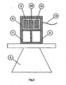
- Fig. 2 shows the basic design of a fill level meter 2 with which the method according to the invention can be carried out.
- a radar pulse or ultrasound pulse generated by a transmitting device 5 is emitted by way of the aerial 6 of the fill level meter 2 in the direction of the medium 3 to be measured.
- the signal fractions reflected by the medium 3 and by other installations 4 are received by the aerial 6 after a distance-dependent runtime, and are transmitted to a receiving and processing unit 7.
- the signals are demodulated if necessary and are then in a known way amplified, filtered and transformed to binary representation by means of an analog-digital converter.
- the digitalised echo curve obtained in this way is finally archived in a volatile memory 9 of an evaluation unit 8.
- the evaluation unit 8 analyses the transferred echo envelope curve and from it determines the present position of the medium 3 to be measured. The results of the analysis can then be made available to a higher-order control system by means of a communication connection 12, such as for example a 4-20 mA line.
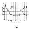
- Fig. 4 shows an example of such a digitised echo envelope curve as it is generated in an application according to Fig. 1.
- the echo curve shown has two echoes 13, 14 which are clearly visible.
- the first echo 13, at approximately 0.35 m, is caused by reflection of the emitted pulse on the pipeline 4 shown in Fig. 1.
- the evaluation unit 8 should therefore recognise this echo as a parasitic echo.
- the second, large, echo 14 is at a distance of 1.80 m; it is caused by reflection from the bulk material (contents) 3.
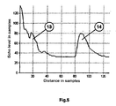
- the echo curve used in the following example is shown in Fig. 5.
- the echo curve essentially corresponds to the echo curve shown in Fig. 4, except that the echo curve in Fig. 5 has the non-dimensional values that are customary in the fill level meter.
- the evaluation unit 8 comprises a non-volatile storage unit 10 as well as a processor unit 11 for implementing the method according to the invention.
- the calculation specifications archived in the non-volatile storage device 10 are explained in more detail in the flow chart shown in Fig. 6.
- Fig. 3 shows a diagrammatic representation of an evaluation device 15 which, by applying the method according to the invention, assesses and evaluates the echoes received by the fill level meter 2 of Fig. 1.
- the evaluation device 15 analogously to the fill level meter 2, comprises a volatile memory 9, a non-volatile storage unit 10 as well as a processor unit 11.
- the evaluation device 30 can be in a location other than directly on a container and is therefore suited to simultaneously evaluate fill level envelope curves of several fill level meters.
- the echo curve archived in the volatile memory 9 is filtered by means of a one-dimensional or multi-dimensional signal processing method, for example to suppress noise fractions contained therein. From the filtered envelope curve obtained in this way, subsequently in step 3000 typical echo characteristics of the echoes contained therein are extracted.
- the methods used therein for example first calculate a dynamic threshold which follows the principal curve course (gradient). After the typical echo characteristics such as for example the echo location s and the echo amplitude A have been determined, the echoes contained in the echo curve, which echoes are above this threshold value, are taken over into a temporary echo storage device.
- step 4000 on the basis of the echo characteristics collected so far, an attempt is made to update the parasitic echo storage device of the fill level meter 2.
- Information contained in the parasitic echo storage device is subsequently used to remove known parasitic echoes (false echoes) from the present echo table.
- an attempt is then made to determine the echo that really belongs to the fill level information. If such an echo can be identified, it is precisely measured with the use of the echo curve that exists in the storage device, so as to determine the exact position of the top surface of the contents.
- the measured value obtained is then transferred to a higher-order communication device (not shown), such as for example a process control station.
- Updating the parasitic echo storage device, carried out in step 4000, includes the actual main focus of the present invention.
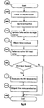
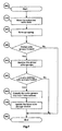
- Fig. 7 shows the associated flow chart.
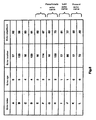
- step 4100 first of all temporarily stored echo characteristics are taken over in the echo storage unit shown in Fig. 8. Apart from the extracted echo characteristics of the present echo curve, the array shown also includes the echo characteristics of the echoes of the past five recordings.
- the echo age t entered in column 2 indicates the number of measurements that have been carried out since the extraction of the present echo curve. Consequently, an echo age t of 2 indicates that the associated echo characteristics originate from the penultimate measurement.
- step 4200 an attempt to group the echoes contained in the echo storage device is made.
- the aim of such grouping is to compose the echoes, caused in each instance by the same reflection origin, of various measurements (in other words of echo curves of different ages) so as to form (global) groups.
- the allocation method applied in this process is explained in more detail in Fig. 9.
- a first step 4220 On condition that the echo storage device (4210) is completely full, as shown in Fig. 8, in a first step 4220 the echoes contained in the echo storage device are composed to form local groups. Only in a second step 4240, on condition that it was possible to identify local echo groups in the echo storage device (4230), is an attempt made to bring the locally found echo groups into a logical connection with the global echo group found in the past. In other words an echo is only supplemented to form an existing global echo group if further echoes exist which form a local group with the first echo. This prevents erroneous allocation of a single echo, for example an echo randomly generated by noise, to the global echo groups. This method returns clearly improved results when compared to the results obtained by direct allocation of individual echoes to echo groups found in the past.
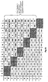
- the echoes of different ages i,j can combinatorially be compared and correlated with each other.
- an evaluation number taking into account the difference in age of the respective echoes, the amplitude difference and the respective local deviation.
- the evaluation numbers resulting from the echoes of Fig. 8 are shown in the table of Fig. 10.
- the calculation instruction mentioned above is only one example of possible implementation. Of course other combinations or weighting of the stated values can be selected, depending on the parameters.
- the corresponding group partner i.e. the corresponding echo from an echo curve of a different age. This corresponding echo is characterised by a minimum evaluation number in the corresponding line. Consequently, the following groups result in the above example: AC BD CE DF EG FH GI HJ IK JL
- these sub-groups can be collected to form larger (local) echo groups.
- the following local echo groups result: ACEGIK BDFHJL.
- step 4240 an attempt is made to combine these local echo groups with the global echo groups that were found in previous runs.
- the global echo groups contain the information of echoes that belong together across a depth of 50 recordings (cf. Fig. 11), wherein of course other depths can also be realised.
- Allocation between the local echo groups in the echo storage device and the global echo groups can again take place by a combinatorial comparison, taking into account the criteria of "amplitude deviation" and "local deviation", wherein for calculating the local deviation, only the latest entry of the global echo group storage device and the oldest entry of the local echo group storage device are used, wherein of course, again, other criteria are possible.
- the global echo group n is supplemented by the oldest echo of the corresponding local echo group m or even by the entire local echo group which has returned the lowest evaluation number when compared to the others.
- step 4250 the oldest entries of the local echo groups are taken over corresponding to the present allocation, into the table of the associated global echo group.
- step 4260 global echo groups that after a parameter-dependent time were unable to carry out an enlargement by allocation to a local group are deleted. In practical application this case always occurs if an echo which has been present up to this time and which was represented by this group suddenly disappears, for example if the useful echo is lost or if caking disappears.
- step 4270 these local echo groups are established as new global groups. In practical use this case always occurs if a new echo arises, for example if caking of contents occurs on a container wall.
- step 4400 of Fig. 7 the found global echo groups are examined more closely.
- the examination aims to detect local changes in sufficiently large global echo groups.
- the analysis is carried out in the method-related steps shown in Fig. 12.
- only those echo groups are used for further examination which reach a parameterisable minimum size. In other words, only those echo groups are investigated whose appearance has already been observed for some time.
- echo groups can then be filtered in relation to location as well as in relation to amplitude using one-dimensional or multi-dimensional signal processing methods, such as for example filtering, averaging, selection and classification.
- filtering for example the location entries and/or amplitude entries of the global echo groups are viewed as a digital signal and are smoothed by settling with adjacent entries. Individual bass values relating to location and amplitude can be effectively suppressed by this measure.
- averaging for example the location entries and/or amplitude entries of the global echo groups are viewed as a digital signal and are smoothed by settling with adjacent entries. Individual noise values relating to location and amplitude can be effectively suppressed by this measure.
- the minimum and maximum entries in the categories of location and amplitude are determined and archived in a separate table.
- step 4600 of Fig. 7 the sufficiently large echo groups are divided into location-dynamic and location-static echo groups. According to the underlying calculation instructions, all those echo groups of sufficient size whose location shift is larger than a parameter-dependent minimal location shift are location-dynamic echoes. The location-dynamic echo that is situated in closest proximity to the fill level meter is then recognised as the fill level echo. Parasitic echoes can thus only be detected in the region between the fill level meter and the present fill level.
- step 4700 the parasitic echo information determined with the above mentioned method is used to update the parasitic echo storage device of the fill level meter.
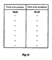
- the average position and the average amplitude are calculated in relation to each global echo group that was identified as a parasitic echo, and are entered into the parasitic echo table of the parasitic echo storage device, as is shown in Fig. 13.
- Obsolete entries in the parasitic echo storage device which entries are from the region between the fill level meter and the present fill level, are also deleted where appropriate.
Landscapes
- Physics & Mathematics (AREA)
- Electromagnetism (AREA)
- General Physics & Mathematics (AREA)
- Radar, Positioning & Navigation (AREA)
- Engineering & Computer Science (AREA)
- Fluid Mechanics (AREA)
- Remote Sensing (AREA)
- Thermal Sciences (AREA)
- Computer Networks & Wireless Communication (AREA)
- Acoustics & Sound (AREA)
- Measurement Of Velocity Or Position Using Acoustic Or Ultrasonic Waves (AREA)
- Radar Systems Or Details Thereof (AREA)
- Measurement Of Levels Of Liquids Or Fluent Solid Materials (AREA)
Applications Claiming Priority (1)
| Application Number | Priority Date | Filing Date | Title |
|---|---|---|---|
| US60192904P | 2004-08-16 | 2004-08-16 |
Publications (2)
| Publication Number | Publication Date |
|---|---|
| EP1628119A2 true EP1628119A2 (de) | 2006-02-22 |
| EP1628119A3 EP1628119A3 (de) | 2012-07-25 |
Family
ID=35385176
Family Applications (1)
| Application Number | Title | Priority Date | Filing Date |
|---|---|---|---|
| EP05017497A Withdrawn EP1628119A3 (de) | 2004-08-16 | 2005-08-11 | Füllstandmessradargerät mit automatischer Echosignalbestimmung |
Country Status (5)
| Country | Link |
|---|---|
| US (2) | US7333900B2 (de) |
| EP (1) | EP1628119A3 (de) |
| CN (1) | CN1766673B (de) |
| AU (1) | AU2005203593B2 (de) |
| RU (1) | RU2394211C2 (de) |
Cited By (8)
| Publication number | Priority date | Publication date | Assignee | Title |
|---|---|---|---|---|
| US7333900B2 (en) * | 2004-08-16 | 2008-02-19 | Vega Grieshaber Kg | Automatic parasitic echo storage |
| EP2309235A1 (de) * | 2009-10-12 | 2011-04-13 | VEGA Grieshaber KG | Segmentbasierte Signalverarbeitung |
| EP2366983A1 (de) | 2010-03-17 | 2011-09-21 | VEGA Grieshaber KG | Mobilitätserkennung in Füllstandmessgeräten |
| EP2372319A1 (de) | 2010-03-26 | 2011-10-05 | VEGA Grieshaber KG | Störechospeicherung bei Behälterrauschen |
| EP2423707A1 (de) * | 2010-08-25 | 2012-02-29 | Siemens Aktiengesellschaft | Verfahren zur Bestimmung des Echoabstands in einem akustischen Impulsechomesssystem |
| US9086310B2 (en) | 2011-08-04 | 2015-07-21 | Vega Grieshaber Kg | Tracking with consideration of mobility |
| WO2020016022A1 (de) * | 2018-07-19 | 2020-01-23 | Vega Grieshaber Kg | Feldgerät mit mehreren rechenwerken |
| WO2025202779A1 (en) * | 2024-03-29 | 2025-10-02 | Siemens Aktiengesellschaft | Method for installing a level measuring device |
Families Citing this family (25)
| Publication number | Priority date | Publication date | Assignee | Title |
|---|---|---|---|---|
| DE102006006572A1 (de) * | 2006-02-13 | 2007-08-16 | Vega Grieshaber Kg | Paarweise ZF-Abtastung für Puls-Laufzeit-Füllstandsensoren |
| US7551122B1 (en) * | 2007-12-06 | 2009-06-23 | Rosemount Tank Radar Ab | Radar level gauge system and method providing a signal indicative of process reliability |
| DE102007060579B4 (de) * | 2007-12-13 | 2019-04-25 | Endress+Hauser SE+Co. KG | Verfahren zur Ermittlung und/oder zur Beurteilung des Befüllzustands eines mit zumindest einem Medium gefüllten Behälters |
| DE102009001010B4 (de) | 2008-12-30 | 2023-06-15 | Endress+Hauser SE+Co. KG | Verfahren zur Ermittlung und Überwachung des Füllstands eines Mediums in einem Behälter nach einem Laufzeitmessverfahren |
| EP2226615B1 (de) * | 2009-03-02 | 2018-08-22 | VEGA Grieshaber KG | Messen von Füllständen mittels Auswerten einer Echokurve |
| DE102010042525A1 (de) * | 2010-10-15 | 2012-04-19 | Endress + Hauser Gmbh + Co. Kg | Verfahren zur Ermittlung und Überwachung des Füllstands eines Mediums in einem Behälter mittels eines Füllstandsmessgeräts nach einem Laufzeitmessverfahren |
| EP2527802B1 (de) * | 2011-05-27 | 2019-12-18 | VEGA Grieshaber KG | Vorrichtung und Verfahren zur Ermittlung von Medien- und Behältereigenschaften |
| EP2527804B1 (de) * | 2011-05-27 | 2020-04-29 | VEGA Grieshaber KG | Verfahren zur Erkennung von Mehrfach- und Bodenechos |
| EP2584324B1 (de) * | 2011-10-17 | 2018-09-19 | VEGA Grieshaber KG | Füllstandsmessgerät und Verfahren zur Bestimmung eines funktionalen Zusammenhangs zwischen verschiedenen Tracks |
| US9518860B2 (en) * | 2013-01-31 | 2016-12-13 | Apm Automation Solutions Ltd | System and method for fuzzy logic based measurement of a content of a bin |
| DE102013103532A1 (de) * | 2013-04-09 | 2014-10-09 | Endress + Hauser Gmbh + Co. Kg | Verfahren zur Füllstandsmessung nach dem Laufzeitprinzip |
| US11099166B2 (en) | 2014-04-04 | 2021-08-24 | Nectar, Inc. | Container content quantity measurement and analysis |
| US10078003B2 (en) | 2014-06-04 | 2018-09-18 | Nectar, Inc. | Sensor device configuration |
| US10591345B2 (en) | 2014-06-04 | 2020-03-17 | Nectar, Inc. | Sensor device configuration |
| US10670444B2 (en) | 2014-04-04 | 2020-06-02 | Nectar, Inc. | Content quantity detection signal processing |
| US11012764B2 (en) | 2014-06-04 | 2021-05-18 | Nectar, Inc. | Interrogation signal parameter configuration |
| US10324075B2 (en) | 2014-04-04 | 2019-06-18 | Nectar, Inc. | Transmitter and receiver configuration for detecting content level |
| CN105300468B (zh) * | 2014-07-22 | 2020-09-18 | 罗斯蒙特储罐雷达股份公司 | 基于模糊逻辑测量仓的内容物的系统和方法 |
| US20160313173A1 (en) * | 2015-04-22 | 2016-10-27 | Honeywell International Inc. | Method and apparatus for level measurements or other measurements using time of flight calculations and estimates of false echoes |
| EP3258296B1 (de) * | 2016-06-14 | 2023-07-26 | VEGA Grieshaber KG | Reflexionsmikrowellenschranke |
| HRP20221145T1 (hr) * | 2017-05-09 | 2022-11-25 | Vega Grieshaber Kg | Mjerenje razine punjenja, mjerenje tlaka ili mjerenje protoka s kratkim vremenom mjerenja |
| CN111052758A (zh) * | 2017-05-11 | 2020-04-21 | 尼科达公司 | 内容物的量的检测和分析 |
| US11237036B2 (en) | 2017-05-11 | 2022-02-01 | Nectar, Inc. | Base station and advertising packets of sensors detecting content level |
| US11274955B2 (en) | 2018-06-12 | 2022-03-15 | Nectar, Inc. | Fouling mitigation and measuring vessel with container fill sensor |
| CN109490342B (zh) * | 2018-11-13 | 2020-09-11 | 中国科学院沈阳自动化研究所 | 一种基于导波雷达液位计评估液体介电常数的方法 |
Citations (6)
| Publication number | Priority date | Publication date | Assignee | Title |
|---|---|---|---|---|
| DE3337690A1 (de) | 1983-10-17 | 1985-04-25 | VEGA Grieshaber GmbH & Co, 7620 Wolfach | Verfahren und vorrichtung zur messung des fuellstands in einem behaelter mittels schall-/ultraschallwellen |
| US5157639A (en) | 1990-09-04 | 1992-10-20 | Magnetrol International | Ultrasonic detector |
| DE4223346A1 (de) | 1992-07-16 | 1994-01-20 | Vega Grieshaber Gmbh & Co | Anordnung und Verfahren zur berührungslosen Abstandsmessung mit Hilfe von Impuls-Echo-Signalen |
| DE4234300A1 (de) | 1992-10-12 | 1994-04-14 | Vega Grieshaber Gmbh & Co | Füllstand-Meßverfahren |
| EP0689679B1 (de) | 1993-03-16 | 1998-05-27 | Siemens Aktiengesellschaft | Verfahren zur erkennung und separation von nutz- und störechos im empfangssignal von abstandssensoren, welche nach dem impuls-echo-prinzip arbeiten |
| DE4407369C2 (de) | 1994-03-05 | 1999-09-30 | Grieshaber Vega Kg | Verfahren und Schaltungsanordnung zur Laufzeitmessung sowie deren Verwendung |
Family Cites Families (20)
| Publication number | Priority date | Publication date | Assignee | Title |
|---|---|---|---|---|
| US4821569A (en) * | 1987-10-30 | 1989-04-18 | Fischer & Porter Co. | Parasitic echo pulse rejector for ultrasonic liquid level meter |
| DE4100338A1 (de) * | 1991-01-08 | 1992-07-09 | Nied Roland | Verfahren zum ermitteln des grades der befuellung eines behaelters |
| JPH06507598A (ja) * | 1991-05-28 | 1994-09-01 | プラッケン,ボウウエ | 物体特に充満袋をそれらが後方に傾いて重なるように一列に配置するための装置 |
| DE4139146A1 (de) * | 1991-11-28 | 1993-06-03 | Siemens Ag | Verfahren und einrichtung zur bestimmung, ob in einem behaelter fluessigkeit enthalten ist |
| DE4218303C1 (de) | 1992-06-03 | 1994-03-03 | Endress Hauser Gmbh Co | Verfahren und Anordnung zur Abstandsmessung nach dem Impulslaufzeitprinzip |
| DE4232346C2 (de) | 1992-09-26 | 1994-09-29 | Konstanzer Michael Dipl Ing Fh | Vorrichtung zum Messen von Füllstandshöhen von in Abscheiderbecken befindlichen Medien |
| US6046960A (en) * | 1993-09-16 | 2000-04-04 | Simmonds Precision Products, Inc. | Apparatus and method for discriminating true and false ultrasonic echoes |
| DE19540170C2 (de) | 1995-10-27 | 1998-01-29 | Endress Hauser Gmbh Co | Verfahren und Anordnung zur Unterdrückung von Festzielechos bei der Abstandsmessung nach dem Impulslaufzeitprinzip |
| RU2125715C1 (ru) * | 1997-03-04 | 1999-01-27 | Кузнецов Владимир Андреевич | Устройство для измерения уровня жидкости |
| CN2289217Y (zh) * | 1997-04-01 | 1998-08-26 | 上海凯力博电器仪表成套有限公司 | 一体化超声波物位计 |
| RU2126145C1 (ru) * | 1997-08-20 | 1999-02-10 | Акционерное общество закрытого типа "Лимако" | Уровнемер |
| DE19824267A1 (de) * | 1998-05-29 | 1999-12-02 | Siemens Ag | Verfahren zur Erkennung von Nutz- und Störechos im Empfangssignal von Abstandssensoren sowie Anordnung zur Durchführung des Verfahrens |
| DE19860901A1 (de) * | 1998-12-30 | 2000-07-06 | Bosch Gmbh Robert | Vorrichtung und Verfahren zur Ermittlung der Lage und/oder der Bewegung einer Oberfläche einer in einem Behälter enthaltenen Flüssigkeit |
| AU5746399A (en) * | 1999-09-07 | 2001-04-10 | Endress & Hauser GMBH & Co. KG. | Device for determining a physical process variable of a medium |
| CA2507422A1 (en) * | 2000-07-07 | 2002-01-17 | Seiko Epson Corporation | Liquid container, ink jet recording apparatus, apparatus and method for controlling the same, apparatus and method for detecting liquid consumption state |
| US6684919B2 (en) * | 2001-02-08 | 2004-02-03 | Vega Grieshaber Kg | Filling level measuring device and method for the non-contact determination of the filling level of a filling product in a receptacle |
| AU2003250981B2 (en) * | 2002-07-19 | 2009-05-28 | Vega Grieshaber Kg | Method and device for determining an expectancy range for a level echo and a spurious echo |
| DE10260962A1 (de) * | 2002-12-20 | 2004-07-01 | Endress + Hauser Gmbh + Co. Kg | Füllstandsmeßgerät und Verfahren zur Füllstandsmessung nach dem Laufzeitprinzip |
| DE10325267A1 (de) * | 2003-06-03 | 2004-12-23 | Endress + Hauser Gmbh + Co. Kg | Anordnung und Verfahren zur Füllstandsmessung |
| US7333900B2 (en) * | 2004-08-16 | 2008-02-19 | Vega Grieshaber Kg | Automatic parasitic echo storage |
-
2005
- 2005-08-11 US US11/202,007 patent/US7333900B2/en not_active Expired - Lifetime
- 2005-08-11 EP EP05017497A patent/EP1628119A3/de not_active Withdrawn
- 2005-08-12 AU AU2005203593A patent/AU2005203593B2/en not_active Ceased
- 2005-08-15 RU RU2005125834/09A patent/RU2394211C2/ru active
- 2005-08-16 CN CN2005101249559A patent/CN1766673B/zh not_active Expired - Fee Related
-
2007
- 2007-12-20 US US11/961,185 patent/US7747397B2/en not_active Expired - Fee Related
Patent Citations (6)
| Publication number | Priority date | Publication date | Assignee | Title |
|---|---|---|---|---|
| DE3337690A1 (de) | 1983-10-17 | 1985-04-25 | VEGA Grieshaber GmbH & Co, 7620 Wolfach | Verfahren und vorrichtung zur messung des fuellstands in einem behaelter mittels schall-/ultraschallwellen |
| US5157639A (en) | 1990-09-04 | 1992-10-20 | Magnetrol International | Ultrasonic detector |
| DE4223346A1 (de) | 1992-07-16 | 1994-01-20 | Vega Grieshaber Gmbh & Co | Anordnung und Verfahren zur berührungslosen Abstandsmessung mit Hilfe von Impuls-Echo-Signalen |
| DE4234300A1 (de) | 1992-10-12 | 1994-04-14 | Vega Grieshaber Gmbh & Co | Füllstand-Meßverfahren |
| EP0689679B1 (de) | 1993-03-16 | 1998-05-27 | Siemens Aktiengesellschaft | Verfahren zur erkennung und separation von nutz- und störechos im empfangssignal von abstandssensoren, welche nach dem impuls-echo-prinzip arbeiten |
| DE4407369C2 (de) | 1994-03-05 | 1999-09-30 | Grieshaber Vega Kg | Verfahren und Schaltungsanordnung zur Laufzeitmessung sowie deren Verwendung |
Non-Patent Citations (2)
| Title |
|---|
| M. SKOLNIK: "INTRODUCTION TO RADAR SYSTEMS", 1980, MCGRAW-HILL |
| PETER DEVINE: "RADAR LEVEL MEASUREMENT - THE USERS GUIDE", 2000, VEGA CONTROLLS LTD. |
Cited By (16)
| Publication number | Priority date | Publication date | Assignee | Title |
|---|---|---|---|---|
| US7333900B2 (en) * | 2004-08-16 | 2008-02-19 | Vega Grieshaber Kg | Automatic parasitic echo storage |
| US8380449B2 (en) | 2009-10-12 | 2013-02-19 | Vega Grieshaber Kg | Segment-based signal processing |
| EP2309235A1 (de) * | 2009-10-12 | 2011-04-13 | VEGA Grieshaber KG | Segmentbasierte Signalverarbeitung |
| EP2366983A1 (de) | 2010-03-17 | 2011-09-21 | VEGA Grieshaber KG | Mobilitätserkennung in Füllstandmessgeräten |
| US8655605B2 (en) | 2010-03-17 | 2014-02-18 | Vega Grieshaber Kg | Mobility detection in fill-level measuring devices |
| EP2372318A1 (de) | 2010-03-26 | 2011-10-05 | VEGA Grieshaber KG | Störechospeicherung bei Behälterrauschen |
| EP2372319A1 (de) | 2010-03-26 | 2011-10-05 | VEGA Grieshaber KG | Störechospeicherung bei Behälterrauschen |
| US8670950B2 (en) | 2010-03-26 | 2014-03-11 | Vega Grieshaber Kg | False echo storage in case of container noise |
| EP2423707A1 (de) * | 2010-08-25 | 2012-02-29 | Siemens Aktiengesellschaft | Verfahren zur Bestimmung des Echoabstands in einem akustischen Impulsechomesssystem |
| US8593908B2 (en) | 2010-08-25 | 2013-11-26 | Siemens Aktiengesellschaft | Method for determining an echo distance in an acoustic pulse-echo ranging system |
| US9086310B2 (en) | 2011-08-04 | 2015-07-21 | Vega Grieshaber Kg | Tracking with consideration of mobility |
| WO2020016022A1 (de) * | 2018-07-19 | 2020-01-23 | Vega Grieshaber Kg | Feldgerät mit mehreren rechenwerken |
| CN112469975A (zh) * | 2018-07-19 | 2021-03-09 | Vega格里沙贝两合公司 | 具有多个运算单元的现场设备 |
| US11313711B2 (en) | 2018-07-19 | 2022-04-26 | Vega Grieshaber Kg | Field device having a plurality of arithmetic units |
| CN112469975B (zh) * | 2018-07-19 | 2024-11-29 | Vega格里沙贝两合公司 | 具有多个运算单元的现场设备 |
| WO2025202779A1 (en) * | 2024-03-29 | 2025-10-02 | Siemens Aktiengesellschaft | Method for installing a level measuring device |
Also Published As
| Publication number | Publication date |
|---|---|
| AU2005203593A1 (en) | 2006-03-02 |
| US7333900B2 (en) | 2008-02-19 |
| EP1628119A3 (de) | 2012-07-25 |
| US7747397B2 (en) | 2010-06-29 |
| US20060052954A1 (en) | 2006-03-09 |
| US20080154522A1 (en) | 2008-06-26 |
| AU2005203593B2 (en) | 2010-11-04 |
| CN1766673A (zh) | 2006-05-03 |
| RU2005125834A (ru) | 2007-02-20 |
| RU2394211C2 (ru) | 2010-07-10 |
| CN1766673B (zh) | 2012-01-18 |
Similar Documents
| Publication | Publication Date | Title |
|---|---|---|
| US7747397B2 (en) | Automatic parasitic echo storage | |
| US7111509B2 (en) | Method and device for determining an expectancy range for a filling level echo and a false echo | |
| EP2071302B1 (de) | Radarpegelmesssystem und Verfahren zur Bereitstellung eines Signals, das auf die Messzuverlässigkeit hinweist | |
| EP2166320B1 (de) | Vorrichtung und Verfahren zur dynamischen Spitzenwertdetektion, Identifizierung und Verfolgung bei Pegelmessanwendungen | |
| EP2699897B1 (de) | System und verfahren zur identifikation von flüssigkeiten und zur überwachung der qualität einer flüssigkeit in einem behälter | |
| US9086310B2 (en) | Tracking with consideration of mobility | |
| KR100991160B1 (ko) | 레이더 레벨 게이지 시스템에서의 탱크 신호의 처리 | |
| US9316480B2 (en) | Method of filling level measurement of layered media | |
| EP2016441B1 (de) | Verfahren zum filtern von seegangsecho in einem radarecho unter verwendung eines hydrografischen modells | |
| EP2103957A1 (de) | Bau eines Nachweisgitters aus mehreren Sensormessungen | |
| US8655605B2 (en) | Mobility detection in fill-level measuring devices | |
| CN101087996A (zh) | 雷达水准仪系统 | |
| US10393565B2 (en) | Determination of container and interference point profiles | |
| EP2474836A1 (de) | Verfahren zur Verarbeitung eines Echos in einem Impulsechomesssystem | |
| RU2576341C2 (ru) | Отслеживание на основе фазы | |
| CN105408729A (zh) | 使用传播时间测量法确定和监控容器中的介质的料位的方法 | |
| US8065912B2 (en) | Filling level sensor and method for measuring filling level | |
| US20100134346A1 (en) | Method for the multidimensional temporal kinematic filtering of radar blips, from antenna revolution to antenna revolution | |
| HK1086329A (en) | Radar level measurement device with automatic echo signal determination | |
| AU2015216751A1 (en) | Method of identifying reflected signals | |
| CN121855652A (zh) | 一种基于雷达水位监测规避水面漂浮物提高监测精度的算法与系统 |
Legal Events
| Date | Code | Title | Description |
|---|---|---|---|
| PUAI | Public reference made under article 153(3) epc to a published international application that has entered the european phase |
Free format text: ORIGINAL CODE: 0009012 |
|
| AK | Designated contracting states |
Kind code of ref document: A2 Designated state(s): AT BE BG CH CY CZ DE DK EE ES FI FR GB GR HU IE IS IT LI LT LU LV MC NL PL PT RO SE SI SK TR |
|
| AX | Request for extension of the european patent |
Extension state: AL BA HR MK YU |
|
| REG | Reference to a national code |
Ref country code: HK Ref legal event code: DE Ref document number: 1086329 Country of ref document: HK |
|
| PUAL | Search report despatched |
Free format text: ORIGINAL CODE: 0009013 |
|
| AK | Designated contracting states |
Kind code of ref document: A3 Designated state(s): AT BE BG CH CY CZ DE DK EE ES FI FR GB GR HU IE IS IT LI LT LU LV MC NL PL PT RO SE SI SK TR |
|
| AX | Request for extension of the european patent |
Extension state: AL BA HR MK YU |
|
| RIC1 | Information provided on ipc code assigned before grant |
Ipc: G01F 23/284 20060101AFI20120618BHEP Ipc: G01F 23/296 20060101ALI20120618BHEP Ipc: G01F 25/00 20060101ALI20120618BHEP |
|
| 17P | Request for examination filed |
Effective date: 20121123 |
|
| REG | Reference to a national code |
Ref country code: HK Ref legal event code: WD Ref document number: 1086329 Country of ref document: HK |
|
| AKX | Designation fees paid |
Designated state(s): AT BE BG CH CY CZ DE DK EE ES FI FR GB GR HU IE IS IT LI LT LU LV MC NL PL PT RO SE SI SK TR |
|
| STAA | Information on the status of an ep patent application or granted ep patent |
Free format text: STATUS: EXAMINATION IS IN PROGRESS |
|
| 17Q | First examination report despatched |
Effective date: 20190121 |
|
| STAA | Information on the status of an ep patent application or granted ep patent |
Free format text: STATUS: THE APPLICATION IS DEEMED TO BE WITHDRAWN |
|
| 18D | Application deemed to be withdrawn |
Effective date: 20190601 |