EP1629079B1 - Vorrichtung zum sammeln und trennen von in der umgebungsluft vorhandenen partikeln und mikroorganismen - Google Patents
Vorrichtung zum sammeln und trennen von in der umgebungsluft vorhandenen partikeln und mikroorganismen Download PDFInfo
- Publication number
- EP1629079B1 EP1629079B1 EP04767250.6A EP04767250A EP1629079B1 EP 1629079 B1 EP1629079 B1 EP 1629079B1 EP 04767250 A EP04767250 A EP 04767250A EP 1629079 B1 EP1629079 B1 EP 1629079B1
- Authority
- EP
- European Patent Office
- Prior art keywords
- enclosure
- air
- microorganisms
- liquid
- particles
- Prior art date
- Legal status (The legal status is an assumption and is not a legal conclusion. Google has not performed a legal analysis and makes no representation as to the accuracy of the status listed.)
- Expired - Lifetime
Links
Images


Classifications
-
- G—PHYSICS
- G01—MEASURING; TESTING
- G01N—INVESTIGATING OR ANALYSING MATERIALS BY DETERMINING THEIR CHEMICAL OR PHYSICAL PROPERTIES
- G01N1/00—Sampling; Preparing specimens for investigation
- G01N1/02—Devices for withdrawing samples
- G01N1/22—Devices for withdrawing samples in the gaseous state
- G01N1/2202—Devices for withdrawing samples in the gaseous state involving separation of sample components during sampling
- G01N1/2211—Devices for withdrawing samples in the gaseous state involving separation of sample components during sampling with cyclones
-
- B—PERFORMING OPERATIONS; TRANSPORTING
- B01—PHYSICAL OR CHEMICAL PROCESSES OR APPARATUS IN GENERAL
- B01D—SEPARATION
- B01D45/00—Separating dispersed particles from gases or vapours by gravity, inertia, or centrifugal forces
- B01D45/12—Separating dispersed particles from gases or vapours by gravity, inertia, or centrifugal forces by centrifugal forces
-
- G—PHYSICS
- G01—MEASURING; TESTING
- G01N—INVESTIGATING OR ANALYSING MATERIALS BY DETERMINING THEIR CHEMICAL OR PHYSICAL PROPERTIES
- G01N33/00—Investigating or analysing materials by specific methods not covered by groups G01N1/00 - G01N31/00
- G01N33/0004—Gaseous mixtures, e.g. polluted air
- G01N33/0009—General constructional details of gas analysers, e.g. portable test equipment
- G01N33/0011—Sample conditioning
-
- B—PERFORMING OPERATIONS; TRANSPORTING
- B01—PHYSICAL OR CHEMICAL PROCESSES OR APPARATUS IN GENERAL
- B01D—SEPARATION
- B01D2257/00—Components to be removed
- B01D2257/91—Bacteria; Microorganisms
-
- G—PHYSICS
- G01—MEASURING; TESTING
- G01N—INVESTIGATING OR ANALYSING MATERIALS BY DETERMINING THEIR CHEMICAL OR PHYSICAL PROPERTIES
- G01N1/00—Sampling; Preparing specimens for investigation
- G01N1/02—Devices for withdrawing samples
- G01N1/22—Devices for withdrawing samples in the gaseous state
- G01N1/2273—Atmospheric sampling
-
- G—PHYSICS
- G01—MEASURING; TESTING
- G01N—INVESTIGATING OR ANALYSING MATERIALS BY DETERMINING THEIR CHEMICAL OR PHYSICAL PROPERTIES
- G01N1/00—Sampling; Preparing specimens for investigation
- G01N1/02—Devices for withdrawing samples
- G01N1/22—Devices for withdrawing samples in the gaseous state
- G01N1/24—Suction devices
-
- G—PHYSICS
- G01—MEASURING; TESTING
- G01N—INVESTIGATING OR ANALYSING MATERIALS BY DETERMINING THEIR CHEMICAL OR PHYSICAL PROPERTIES
- G01N1/00—Sampling; Preparing specimens for investigation
- G01N1/02—Devices for withdrawing samples
- G01N1/22—Devices for withdrawing samples in the gaseous state
- G01N1/2202—Devices for withdrawing samples in the gaseous state involving separation of sample components during sampling
- G01N2001/222—Other features
- G01N2001/2223—Other features aerosol sampling devices
Definitions
- the invention relates to a device for collecting and separating particles and microorganisms present in the ambient air, for the purposes of identification and enumeration of these particles and microorganisms.
- the qualitative and quantitative evaluation of particulate matter and microorganisms in the air is important in many areas such as the pharmaceutical industry, the food industry, the medical sector, the health services, the veterinary services, etc.
- the dimensions of the particles and microorganisms to be collected may vary from approximately 0.5 to 15 ⁇ m.
- the biological particles present in the air include in particular bacteria, molds, viruses, pollen, ... and are generally collected by impact on a nutrient or selective agar, or by impact on a liquid surface or by centrifugation in liquid medium.
- This method can therefore be performed with very low air suction rates and for a short time not to damage the microorganisms collected and also not to dry the agar, these air flows being typically less than 100 liters per minute.
- the microbial load measured with this method is generally underestimated.
- the particles are sucked into a cylindrical chamber where they are rotated and fall into a tube containing a liquid.
- the largest particles are plated on the walls of the chamber and recovered at the bottom while the finest particles are carried to the outlet by the air flow and are not collected.
- the air flows used are relatively high to ensure a sufficient collection of particles and micro-organisms and the dimensions and weight of the materials used (cyclonic chamber, air suction means) are relatively important. so that these materials are fixed and permanently installed, which limits their use.
- the collected particles are generally recovered in a bottle at the lower end of the cylindrical chamber, and this bottle is closed by means of a stopper. This way of doing does not guarantee, on the one hand, that all the separated particles are collected well in the bottle and does not avoid, on the other hand, the risks of contamination when the bottle is separated from the cyclone chamber.
- the invention relates to a device for collecting and separating particles and microorganisms present in the ambient air which combines the advantages of known techniques without the disadvantages.
- the invention is the same element that serves for the separation and collection of particles and microorganisms present in the ambient air and their transport for analysis. This reduces handling and reduces the risk of contamination of the particles and microorganisms collected. This also ensures that the particles and microorganisms analyzed represent 100% of the particles and microorganisms collected.
- the enclosure comprises means for automatically closing the orifices of its upper end, these means being open when the enclosure is mounted on the device and closed when it is removed from the device.
- these automatic sealing means comprise an annular diaphragm and elastic return means of the diaphragm in the closed position of the open upper end of the enclosure.
- Other means are provided if necessary to close one or more air inlets in the enclosure.
- the enclosure can be mounted on the device by resilient latching and quarter-turn rotation, the translational movement of the enclosure during its latching or quarter-turn rotation without difficulty opening or closing the means of automatic shutter mentioned above.
- the device according to the invention has the essential advantage of being able to be used anywhere, thanks to its autonomy, its low volume and its low weight which allow not only to carry it easily but also to handle it with one hand, the place and guide it at will.
- this device it is thus possible, thanks to this device, to take successive samples in several places and by directing the device differently from one place to another, for example in the same room.
- the operator may be provided with equipment including several spare speakers, which allows him to take several samples in a short period of time.
- the removable enclosure is for single use, or it is made of autoclavable material.
- the collection and recovery of the particles and microorganisms in the chamber take place dry and a suitable liquid is then added in a predetermined amount in this lower part to obtain a liquid sample that can then be processed as desired.
- the device comprises liquid injection means in the upper part of the chamber mounted on the device, these injection means opening for example in air inlet means inside the enclosure.
- a liquid sample containing the particles and microorganisms collected is thus directly obtained in the lower part of the chamber.
- the device according to the invention comprises a handle which is connected to the fixed support part of the enclosure and / or to the air suction means and which contains a liquid reservoir, means for pressurizing the liquid in the reservoir and means for connecting the reservoir to injection means in the aforementioned enclosure.
- these connecting means comprise means for controlling the flow of liquid towards the injection means.
- this handle comprises means for controlling the air suction means.
- a sample can last a few minutes and can collect the particles and microorganisms present in a volume of ambient air of between 1 and 2 m 3 .
- the device according to the invention makes it possible to separate and collect particles and microorganisms having dimensions typically between 0.5 and 15 microns approximately.
- a filter suitable can be placed in the axial air outlet of the aforementioned enclosure.
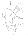
- This device is autonomous, portable and manipulable with one hand and essentially comprises a cylindrical enclosure 10 mounted on a fixed part of the device and comprising a cylindrical body 13 and a lower portion 12 of frustoconical shape, the enclosure 10 defining a centrifugation chamber and being connected to means 14 for suction air.
- the device is equipped with a handle 16 provided with means for controlling the operation of the air suction means, these control means being for example of the push-button or slider type.
- the fixed part of the device on which the enclosure is mounted comprises an upper wall 11 with an axial air outlet 18 and a cylindrical rim 20 oriented downwards and which comprises an orifice connected to an air inlet duct 22. opening tangentially in the enclosure 10.
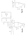
- the wall 11 is integral with the suction means 14 and the axial air outlet 18 is connected to a suction volume formed in the housing of the means 14 and containing a rotor 24 driven by a electric motor and whose rotation causes suction in the conduit 18, an air inlet into the chamber 10 through the conduit 22 and a rotation of the air inside the enclosure as indicated by the arrows in figure 2 .
- the ambient air 26 is thus sucked into the chamber 10 and the particles and microorganisms that it contains are separated by centrifugation and deposited on the inner wall of the chamber 10 and then recovered in the frustoconical lower part 12 whose section is reduced to the bottom and may comprise a cylindrical end 28 closure.
- cylindrical body 13 and the frustoconical portion 12 of the enclosure form a one-piece assembly removably mounted on the cylindrical rim 20, by resilient snapping or quarter turn rotation.
- the air inlet opening and the open upper end of the enclosure 10 may be closed by a cap 42 when the enclosure is dismounted from the device, as shown in FIG. Figure 3a and 3b , the closed enclosure then forming a container that keeps the collected particles and microorganisms and transport them to an analytical laboratory.
- the upper end of the chamber may be equipped with an automatic closure means 29, such as for example an annular diaphragm of the type used in cameras, which is associated with a return spring. and which is actuated in opening when the enclosure 10 is mounted on the device and closed when this enclosure is removed from the device.
- an automatic closure means 29 such as for example an annular diaphragm of the type used in cameras, which is associated with a return spring. and which is actuated in opening when the enclosure 10 is mounted on the device and closed when this enclosure is removed from the device.
- the upper end of the enclosure 10 closed by the automatic closure means 29 may be capped with a cap 42 as shown in FIG. figure 3b for its storage and transport to means of analysis.
- the handle 16 of the device also contains a suitable liquid reservoir 30 (water and a surfactant, or another liquid depending on the analyzes to be performed), the output of which comprises flow control means 32 connected to injection means 34 in the upper part of the enclosure 10.
- a suitable liquid reservoir 30 water and a surfactant, or another liquid depending on the analyzes to be performed
- these injection means 34 open into the conduit 22 for supplying air into the enclosure.
- the fixed upper part of the enclosure comprises a plurality of liquid injection orifices, oriented tangentially and regularly distributed over a circumference of the cylindrical rim and which open into the enclosure through openings in the upper part of the enclosure. the enclosure 10.
- the reservoir 30 is advantageously associated with means 36 of pressurizing the liquid to be injected, these means 36 being of any appropriate type, for example comprising a spring acting on a moving bottom of the tank 30 as shown, a pressurized gas, etc.
- the tank 30 may itself be “monodose”, that is to say, it contains a relatively small amount of liquid sufficient for a sample, or “multidose” and then comprises a larger amount of liquid allowing several successive sampling.
- the means 32 for controlling the injection flow rate are controlled by a slider or a push button 38 carried by the handle 16, in the vicinity of another pushbutton or slider 40 for controlling the operation of the suction means air 14.
- the handle also contains power supply means for the electric motor driving the rotor 24, these means being for example rechargeable accumulators or the like. Alternatively, this electric motor can be powered by connection to an electrical network.
- the enclosure 10 has a diameter of the order of 50 millimeters, the volume of this enclosure including the lower part 12 is of the order of 100 to 200 cm 3 , the air flow sucked into the chamber 10 by the means 14 is between 200 and 400 liters per minute, the volume of liquid injected into the chamber 10 by the means 34 at each sampling is between 5 and 10 ml, the reservoir 30 contains for example 40 ml of liquid (which allows 4 to 8 samples), the installed electrical power is 100 to 200 W, and the total weight of the device is less than 2 kg.
- This device is used as follows:
- the chamber 10 is fixed on the cylindrical rim 20 and the operation of the air suction means 14 is controlled by means of the push-button 40.
- the duration of the sampling is, for example, 5 minutes, which makes it possible to suck about 1 to 2 m 3 of air, the sucked air circulating in the chamber 10 by rotating around it its axis and then up to exit through the conduit 18 and pass into the housing of the means 14 for suction of air to be ejected outside.
- the injection of liquid may be continuous throughout the sampling, or it may take place during part of the sampling.
- the particles and microorganisms conveyed by the sucked air are centrifuged on the inner wall of the chamber 10 and are thus separated from the sucked air which exits via the pipe 18.
- the liquid injected into the chamber 10 circulates as sucked air and performs a thorough washing of the inner surface of this enclosure.
- the collected particles and microorganisms are finally recovered in the lower part 12 and in the cylindrical end 28.
- the enclosure 10 can be withdrawn by unclipping or by quarter turn rotation on the upper cylindrical rim 20 and then the body 13 of the enclosure 10 of the cap 42 which closes all the orifices of the upper part of the enclosure is capped. 10. A small sealed container is thus obtained which can be stored for analysis.
- the small dimensions of the device according to the invention make it possible to carry it with a series of 4 or 5 removable enclosures in a case, which can also contain one or two spare tanks and possibly a second rechargeable battery for the supply of the battery. driving motor of the air suction means 14.
- the air suction means 14 may comprise a small compressed air tank, which will allow air to be drawn into the cylindrical chamber 10 by driving. The device can then be used without risk of explosion caused by an electric spark.
- the liquid reservoir 30 and its pressurizing means 36 may be constituted by a manual or semi-automatic injection syringe.
- the device according to the invention can also be used to take samples and separations of dry particles and microorganisms, the collected and collected particles and micro-organisms then being dissolved in a suitable liquid for analysis.
- Such a device is shown schematically in figure 4 .
- the cylindrical body 13 of the enclosure 10 is closed by an upper cover 44 having an axial air outlet 46 optionally equipped with an automatic closure means such as a rubber membrane or a gasket. sealing for example.
- This enclosure 10 is mounted by clipping or by quarter-turn rotation on a fixed support 20, this support comprising, as in the previous embodiment, tangential air inlet means 22 in the enclosure 10, a conduit 18 air outlet communicating with the volume in which the rotor 24 rotates, and a not shown handle holding and handling of the device.
- the chamber 10 After sampling, the chamber 10 is detached from the support 20, the air inlet orifice in the chamber is closed, then a determined quantity of a suitable liquid can be injected into the chamber 10 via the conduit.
- axial upper 46 to dissolve the particles and microorganisms deposited on the inner walls of the cylindrical body 13 and the lower portion 12 of the enclosure.
- the device according to the invention makes it possible to recover a representative sample of the particles and micro-organisms present in the ambient air by sampling a relatively large volume of ambient air.
- the samples taken are conditioned in the enclosures cylindrical 10 disassembled from the device and are protected against the risk of contamination.
- the concentration factor of the particles and microorganisms removed which are in solution in the injected liquid is adaptable at will.
- the sampling times are adjustable.
- the collected samples are separated from each other in the various cylindrical enclosures 10, which avoids any risk of contamination between these samples.
- obtaining samples in liquid form makes it possible to apply new methods of analysis based on molecular biology techniques, epi-fluorescence microscopies, flow cytometry, bioluminescence, immunology or Chromatography. It is thus possible to evaluate the total microbial flora of the ambient air and / or the viable microbial flora, without being limited to the evaluation of the cultivable flora which represents only about 0.1 to 10% of the total microbial flora.
- the new analytical techniques to which the samples taken by means of the device according to the invention can be subjected also make it possible to specifically search for bacteria or molds or to probe a particular species.
- the device according to the invention and the aforementioned carrying case containing accessories such as removable enclosures, one or more injection liquid tanks, one or more rechargeable accumulators, possibly accumulator charging means, etc., constitute an autonomous and portable kit for the collection and separation of particles and microorganisms present in the ambient air, which finds applications in very numerous and very diverse fields.
Landscapes
- Chemical & Material Sciences (AREA)
- Health & Medical Sciences (AREA)
- Life Sciences & Earth Sciences (AREA)
- Engineering & Computer Science (AREA)
- Analytical Chemistry (AREA)
- General Physics & Mathematics (AREA)
- Pathology (AREA)
- Physics & Mathematics (AREA)
- Immunology (AREA)
- Biochemistry (AREA)
- General Health & Medical Sciences (AREA)
- Chemical Kinetics & Catalysis (AREA)
- Biomedical Technology (AREA)
- Molecular Biology (AREA)
- Combustion & Propulsion (AREA)
- Food Science & Technology (AREA)
- Medicinal Chemistry (AREA)
- Apparatus Associated With Microorganisms And Enzymes (AREA)
- Sampling And Sample Adjustment (AREA)
Claims (17)
- Vorrichtung zum Sammeln und Trennen von in der Umgebungsluft vorhandenen Partikeln und Mikroorganismen, enthaltend Mittel (14) zum Ansaugen von Luft in ein Zentrifugiergefäß (10), das Mittel zum Zurückhalten von Partikeln bzw. Mikroorganismen aufweist, und Mittel (18) zum Ausströmen der angesaugten Luft, dadurch gekennzeichnet, dass das Gefäß (10) an der Vorrichtung abnehmbar montiert ist und einen Behälter zum Transportieren der gesammelten Partikel und Mikroorganismen bildet und im Wesentlichen eine zylindrische Kammer mit einem Volumen von 100 bis 200 cm3 enthält, in welche die mit der angesaugten Luft mitgerissenen Partikel und Mikroorganismen in Drehung um die Achse des Gefäßes versetzt werden und durch Zentrifugieren an der Innenwand des Gefäßes von der angesaugten Luft getrennt werden, wobei dieses Gefäß mit den Mitteln (14) zum Ansaugen von Luft eine eigenständige, tragbare und mit nur einer Hand handhabbare Einheit bildet, wobei die Luftdurchsatzmenge der von den Ansaugmitteln in das Gefäß angesaugten Luft zwischen etwa 200 und 400 Liter pro Minute beträgt.
- Vorrichtung nach Anspruch 1, dadurch gekennzeichnet, dass das Gefäß (10) Mittel zum automatischen Verschließen seines oberen Endes aufweist, die dann offen sind, wenn das Gefäß an der Vorrichtung montiert ist, und dann geschlossen sind, wenn das Gefäß von der Vorrichtung abgenommen ist.
- Vorrichtung nach Anspruch 2, dadurch gekennzeichnet, dass die Mittel zum automatischen Verschließen eine ringförmige Membrane und Mittel zum elastischen Rückstellen der Membrane in den Schließbereich aufweisen.
- Vorrichtung nach einem der vorangehenden Ansprüche, dadurch gekennzeichnet, dass das Gefäß (10) durch elastisches Einrasten oder durch eine Viertelumdrehung an der Vorrichtung montiert ist.
- Vorrichtung nach einem der Ansprüche 1 bis 4, dadurch gekennzeichnet, dass das Gefäß (10) an einer festen oberen Wand (11) montiert ist, die einen axialen Luftauslass (18) und einen tangentialen Lufteinlass (22) aufweist.
- Vorrichtung nach einem der Ansprüche 1 bis 5, dadurch gekennzeichnet, dass sie Mittel (34) zum Einspritzen von Flüssigkeit in den oberen Bereich (11, 20) des Gefäßes aufweist.
- Vorrichtung nach Anspruch 6, dadurch gekennzeichnet, dass die Mittel (34) zum Einspritzen von Flüssigkeit in einen Kanal (22) zum Einströmen von Luft in das Gefäß münden.
- Vorrichtung nach Anspruch 5 und 6 zusammengenommen, dadurch gekennzeichnet, dass die Mittel (34) zum Einspritzen von Flüssigkeit mehrere Öffnungen aufweisen, die in das Gefäß münden und gleichmäßig über einen Umfang einer Randkante (20) der festen oberen Wand (11) verteilt sind.
- Vorrichtung nach einem der Ansprüche 5 bis 8, dadurch gekennzeichnet, dass der axiale Auslass (18) des Gefäßes dazu bestimmt ist, mit einem Anschluss zum Absaugen von Luft verbunden zu werden.
- Vorrichtung nach einem der Ansprüche 5 bis 8, dadurch gekennzeichnet, dass die Mittel (14) zum Ansaugen von Luft fest mit der festen oberen Wand (11, 20) verbunden sind und Luft durch den axialen Auslass (18) des Gefäßes absaugen.
- Vorrichtung nach einem der vorangehenden Ansprüche, dadurch gekennzeichnet, dass sie einen Griff (16) aufweist, der einen Flüssigkeitsvorratsbehälter (30), Mittel (36) zum Unterdrucksetzen der Flüssigkeit in dem Vorratsbehälter und Mittel zum Verbinden des Vorratsbehälters mit Mitteln (34) zum Einspritzen in das vorgenannte Gefäß beinhaltet.
- Vorrichtung nach Anspruch 11, dadurch gekennzeichnet, dass die Verbindungsmittel Mittel (32) zum Einstellen der Durchsatzmenge an Flüssigkeit zu den Einspritzmitteln (34) aufweisen.
- Vorrichtung nach Anspruch 11 oder 12, dadurch gekennzeichnet, dass der Griff (16) Mittel (40) zum Steuern der Luftansaugmittel (14) aufweist.
- Vorrichtung nach einem der vorangehenden Ansprüche, dadurch gekennzeichnet, dass das abnehmbare Gefäß (10) zum einmaligen Gebrauch bestimmt ist oder aus einem autoklavierbaren Material besteht.
- Vorrichtung nach einem der vorangehenden Ansprüche, dadurch gekennzeichnet, dass sie zum Sammeln und Trennen von Partikeln und Mikroorganismen mit Abmessungen zwischen etwa 0,5 und 15 µm bestimmt ist.
- Vorrichtung nach einem der vorangehenden Ansprüche, dadurch gekennzeichnet, dass die Mittel (18) zum Ausströmen von Luft aus dem Gefäß ein Filter zum Abfangen von Partikeln und Mikroorganismen mit Abmessungen von unter etwa 1 µm aufweisen.
- Eigenständiger und tragbarer Teilesatz zum Trennen und Sammeln von in der Umgebungsluft vorhandenen Partikeln und Mikroorganismen, dadurch gekennzeichnet, dass er eine Vorrichtung vom Typ wie in einem der vorangehenden Ansprüche beschrieben und einen Koffer mit Zubehör, wie beispielsweise abnehmbare Austauschgefäße, zumindest einen Vorratsbehälter für Einspritzflüssigkeit und zumindest einen wiederaufladbaren elektrischen Akkumulator enthält.
Applications Claiming Priority (2)
| Application Number | Priority Date | Filing Date | Title |
|---|---|---|---|
| FR0306749A FR2855831B1 (fr) | 2003-06-04 | 2003-06-04 | Dispositif de collecte de particules et de micro-organismes presents dans l'air ambiant |
| PCT/FR2004/001382 WO2004108880A2 (fr) | 2003-06-04 | 2004-06-03 | Dispositif de collecte et de separation de particules et de micro-organismes presents dans l'air ambiant |
Publications (2)
| Publication Number | Publication Date |
|---|---|
| EP1629079A2 EP1629079A2 (de) | 2006-03-01 |
| EP1629079B1 true EP1629079B1 (de) | 2014-01-22 |
Family
ID=33443136
Family Applications (1)
| Application Number | Title | Priority Date | Filing Date |
|---|---|---|---|
| EP04767250.6A Expired - Lifetime EP1629079B1 (de) | 2003-06-04 | 2004-06-03 | Vorrichtung zum sammeln und trennen von in der umgebungsluft vorhandenen partikeln und mikroorganismen |
Country Status (9)
| Country | Link |
|---|---|
| US (1) | US7452394B2 (de) |
| EP (1) | EP1629079B1 (de) |
| JP (1) | JP4571623B2 (de) |
| CN (1) | CN100427580C (de) |
| AU (1) | AU2004245728B2 (de) |
| CA (1) | CA2527937C (de) |
| FR (1) | FR2855831B1 (de) |
| RU (1) | RU2340388C2 (de) |
| WO (1) | WO2004108880A2 (de) |
Families Citing this family (25)
| Publication number | Priority date | Publication date | Assignee | Title |
|---|---|---|---|---|
| WO2005040767A2 (en) | 2003-10-17 | 2005-05-06 | The Government Of The United States Of America As Represented By The Secretary Of The Department Of Health And Human Services, Centers For Disease Control And Prevention | Air-sampling device and method of use |
| FR2905379B1 (fr) | 2006-09-04 | 2008-11-07 | Bertin Technologies Soc Par Ac | Dispositif de collecte et de separation de particules et de microorganismes presents dans l'air ambiant |
| DE102006044546A1 (de) * | 2006-09-22 | 2008-04-03 | Biotest Ag | Luftkeimsammler |
| CN101013069B (zh) * | 2007-02-09 | 2010-09-08 | 中国农业大学 | 一种少量游离细胞或微小样品收集器 |
| GB2449218B (en) * | 2007-05-18 | 2009-04-15 | Jessal Murarji | Gas sampler for vapour detectors |
| FR2917095B1 (fr) * | 2007-06-07 | 2009-07-17 | Biomerieux Sa | Dispositif de lyse de microorganismes presents dans un echantillon environnemental ou clinique et d'extraction des acides nucleiques desdits microorganismes aux fins d'analyse. |
| JP2010197136A (ja) * | 2009-02-24 | 2010-09-09 | Shoei Denshi Kogyo Kk | 測定装置 |
| FR2966839B1 (fr) | 2010-10-27 | 2012-11-30 | Bertin Technologies Sa | Dispositif portable de collecte de particules et de microorganismes |
| DE102011053759A1 (de) * | 2011-09-19 | 2013-03-21 | Helmut Holbach | Sammelvorrichtung zum Sammeln von Substanzen aus einem Gas |
| JP6075979B2 (ja) | 2012-06-27 | 2017-02-08 | リオン株式会社 | 粒子計数システム |
| US20160114279A1 (en) * | 2013-07-13 | 2016-04-28 | Gerhard Kemper | Filter apparatus for extracting fine dust from air |
| JP2015080428A (ja) * | 2013-10-22 | 2015-04-27 | 東洋製罐グループホールディングス株式会社 | 微生物の検査方法 |
| JP6313123B2 (ja) * | 2014-05-28 | 2018-04-18 | 東京エレクトロン株式会社 | 測定装置及び測定方法 |
| JP6328493B2 (ja) * | 2014-05-28 | 2018-05-23 | 東京エレクトロン株式会社 | 測定装置及び測定方法 |
| KR102221557B1 (ko) * | 2014-07-28 | 2021-03-02 | 엘지전자 주식회사 | 부유미생물 측정장치 및 그 측정방법 |
| JP6710553B2 (ja) * | 2015-05-21 | 2020-06-17 | 株式会社堀場製作所 | 試料導入装置 |
| US9745924B2 (en) * | 2015-05-29 | 2017-08-29 | Mann+Hummel Gmbh | Hood of a multi cyclone block of an air cleaner and air cleaner |
| CN106399072B (zh) * | 2016-09-14 | 2019-04-16 | 珠海格力电器股份有限公司 | 样品采样器和采样装置 |
| CN107036855B (zh) * | 2017-06-07 | 2019-06-21 | 江苏省欧萨环境检测技术有限公司 | 一种固定源废气颗粒物采样管 |
| CN107179216B (zh) * | 2017-06-13 | 2019-04-23 | 西南科技大学 | 一种矿物颗粒分离采样装置 |
| JP7320759B2 (ja) * | 2018-04-24 | 2023-08-04 | パナソニックIpマネジメント株式会社 | 検出装置及び検出方法 |
| FR3080780B1 (fr) | 2018-05-04 | 2021-07-09 | Bertin Technologies Sa | Dispositif de collecte de particules ou de micro-organismes |
| CN111606476A (zh) * | 2020-05-26 | 2020-09-01 | 郑州众然供应链管理有限公司 | 一种微生物灭活装置 |
| CN111896338A (zh) * | 2020-08-26 | 2020-11-06 | 黄婷 | 一种便携式气溶胶采样器 |
| CA3223052A1 (en) * | 2021-06-15 | 2022-12-22 | Zachary A. Packingham | Aerosol collectors with removable inlet assembly |
Family Cites Families (10)
| Publication number | Priority date | Publication date | Assignee | Title |
|---|---|---|---|---|
| US3070990A (en) * | 1960-02-11 | 1963-01-01 | Pittsburgh Plate Glass Co | Sampling device and method for analysis of furnace gases |
| SU703122A1 (ru) * | 1977-10-17 | 1979-12-15 | Всесоюзный научно-исследовательский институт прикладной энзимологии | Сепаратор |
| SU921633A1 (ru) * | 1980-09-04 | 1982-04-23 | Предприятие П/Я А-3732 | Циклон |
| US5500369A (en) * | 1993-10-12 | 1996-03-19 | Nch Corporation | Air sampler |
| CA2151893A1 (en) * | 1995-06-15 | 1996-12-16 | Jean J.O. Gravel | Apparatus for separating solid particles from a gas and for injecting the so-separated particles into a reaction vessel |
| US5902385A (en) * | 1997-06-23 | 1999-05-11 | Skc, Inc. | Swirling aerosol collector |
| JPH11225743A (ja) * | 1998-02-19 | 1999-08-24 | E Jet:Kk | 浮遊菌や粉塵の捕集装置 |
| GB9911336D0 (en) * | 1999-05-15 | 1999-07-14 | Graseby Dynamics Ltd | Separation and collection of analyte materials |
| US6468330B1 (en) * | 1999-06-14 | 2002-10-22 | Innovatek, Inc. | Mini-cyclone biocollector and concentrator |
| US6589323B1 (en) * | 1999-11-19 | 2003-07-08 | Amos Korin | System for cleaning air and method for using same |
-
2003
- 2003-06-04 FR FR0306749A patent/FR2855831B1/fr not_active Expired - Lifetime
-
2004
- 2004-06-03 AU AU2004245728A patent/AU2004245728B2/en not_active Expired
- 2004-06-03 EP EP04767250.6A patent/EP1629079B1/de not_active Expired - Lifetime
- 2004-06-03 RU RU2005141407/13A patent/RU2340388C2/ru active
- 2004-06-03 CA CA2527937A patent/CA2527937C/fr not_active Expired - Lifetime
- 2004-06-03 JP JP2006508356A patent/JP4571623B2/ja not_active Expired - Lifetime
- 2004-06-03 WO PCT/FR2004/001382 patent/WO2004108880A2/fr not_active Ceased
- 2004-06-03 CN CNB2004800183134A patent/CN100427580C/zh not_active Expired - Lifetime
-
2005
- 2005-12-01 US US11/291,724 patent/US7452394B2/en not_active Expired - Lifetime
Also Published As
| Publication number | Publication date |
|---|---|
| WO2004108880A3 (fr) | 2005-05-06 |
| CA2527937A1 (fr) | 2004-12-16 |
| US20060144025A1 (en) | 2006-07-06 |
| CA2527937C (fr) | 2013-08-06 |
| RU2340388C2 (ru) | 2008-12-10 |
| FR2855831B1 (fr) | 2005-09-02 |
| WO2004108880A2 (fr) | 2004-12-16 |
| JP2006526401A (ja) | 2006-11-24 |
| FR2855831A1 (fr) | 2004-12-10 |
| JP4571623B2 (ja) | 2010-10-27 |
| RU2005141407A (ru) | 2006-09-10 |
| EP1629079A2 (de) | 2006-03-01 |
| US7452394B2 (en) | 2008-11-18 |
| AU2004245728A1 (en) | 2004-12-16 |
| CN100427580C (zh) | 2008-10-22 |
| CN1813058A (zh) | 2006-08-02 |
| AU2004245728B2 (en) | 2010-03-11 |
Similar Documents
| Publication | Publication Date | Title |
|---|---|---|
| CA2527937C (fr) | Dispositif de collecte et de separation de particules et de micro-organismes presents dans l'air ambiant | |
| EP2633025B1 (de) | Tragbare vorrichtung zum sammeln von partikeln und mikroorganismen | |
| EP1385411B1 (de) | Vorrichtung zum verdichten von abfall in einem staubsauger | |
| EP0525493B1 (de) | Blutsammlungs- und Filtrationsvorrichtung | |
| US6550347B2 (en) | Vacuum air component sampler | |
| US20100180699A1 (en) | Portable contaminant sampling system | |
| FR2857847A1 (fr) | Receptacle de poussiere pour robot de nettoyage et son procede de mise en oeuvre | |
| EP3673126A1 (de) | Schwimmbeckenreiniger mit einer durch zentrifugalspinnen und filtration arbeitenden ablagerungstrennvorrichtung | |
| WO2008029014A3 (fr) | Dispositif de collecte et de separation de particules et de microorganismes presents dans l'air ambiant | |
| FR3107464A1 (fr) | Aspirateur utilisable notamment dans des boîtes à gants | |
| EP3788342B1 (de) | Vorrichtung zum sammeln von partikeln oder mikroorganismen | |
| FR2876115A1 (fr) | Procede, dispositif et systeme de prelevement d'air pour une analyse microbiologique | |
| EP1875847A1 (de) | Vorrichtung zum Abscheiden, durch Aufsaugen, von staubhaltigen Gasen | |
| FR2773217A1 (fr) | Utilisation d'une interaction entre un gaz et un liquide pour le prelevement des elements gazeux et particulaires d'un milieu gazeux en vue de leur analyse | |
| US9097624B1 (en) | External filter assembly adapted for modifying a suction cleaning device to perform biological sampling | |
| KR102702105B1 (ko) | 휴대용 dna 검체 채취장치 | |
| EP4330648B1 (de) | Verfahren zur extraktion und erkennung von bestimmten riechenden molekülen und extraktionsvorrichtung zur durchführung des verfahrens | |
| CN214793849U (zh) | 一种鼠粪采集装置 | |
| EP4043673B1 (de) | Filtersystem mit kartusche, die in einem flexiblen beutel enthalten ist, und mit einem solchen system ausgestatteter staubsauger | |
| EP4290211B1 (de) | Verfahren zur erkennung der anwesenheit eines zielmaterials |
Legal Events
| Date | Code | Title | Description |
|---|---|---|---|
| PUAI | Public reference made under article 153(3) epc to a published international application that has entered the european phase |
Free format text: ORIGINAL CODE: 0009012 |
|
| 17P | Request for examination filed |
Effective date: 20051125 |
|
| AK | Designated contracting states |
Kind code of ref document: A2 Designated state(s): AT BE BG CH CY CZ DE DK EE ES FI FR GB GR HU IE IT LI LU MC NL PL PT RO SE SI SK TR |
|
| DAX | Request for extension of the european patent (deleted) | ||
| RIN1 | Information on inventor provided before grant (corrected) |
Inventor name: VALLAYER, BRUNO Inventor name: SOREL, EMMANUELLE Inventor name: TROUCHET, DANIEL Inventor name: VERDIER, AMANDINE |
|
| 17Q | First examination report despatched |
Effective date: 20111010 |
|
| REG | Reference to a national code |
Ref country code: DE Ref legal event code: R079 Ref document number: 602004044323 Country of ref document: DE Free format text: PREVIOUS MAIN CLASS: C12M0001260000 Ipc: B01D0045120000 |
|
| RIC1 | Information provided on ipc code assigned before grant |
Ipc: G01N 1/22 20060101ALI20130610BHEP Ipc: B01D 45/12 20060101AFI20130610BHEP Ipc: G01N 33/00 20060101ALI20130610BHEP Ipc: G01N 1/24 20060101ALI20130610BHEP |
|
| GRAJ | Information related to disapproval of communication of intention to grant by the applicant or resumption of examination proceedings by the epo deleted |
Free format text: ORIGINAL CODE: EPIDOSDIGR1 |
|
| GRAP | Despatch of communication of intention to grant a patent |
Free format text: ORIGINAL CODE: EPIDOSNIGR1 |
|
| INTG | Intention to grant announced |
Effective date: 20130806 |
|
| GRAS | Grant fee paid |
Free format text: ORIGINAL CODE: EPIDOSNIGR3 |
|
| GRAA | (expected) grant |
Free format text: ORIGINAL CODE: 0009210 |
|
| AK | Designated contracting states |
Kind code of ref document: B1 Designated state(s): AT BE BG CH CY CZ DE DK EE ES FI FR GB GR HU IE IT LI LU MC NL PL PT RO SE SI SK TR |
|
| REG | Reference to a national code |
Ref country code: GB Ref legal event code: FG4D Free format text: NOT ENGLISH |
|
| REG | Reference to a national code |
Ref country code: CH Ref legal event code: EP |
|
| REG | Reference to a national code |
Ref country code: AT Ref legal event code: REF Ref document number: 650496 Country of ref document: AT Kind code of ref document: T Effective date: 20140215 |
|
| REG | Reference to a national code |
Ref country code: IE Ref legal event code: FG4D Free format text: LANGUAGE OF EP DOCUMENT: FRENCH |
|
| REG | Reference to a national code |
Ref country code: DE Ref legal event code: R096 Ref document number: 602004044323 Country of ref document: DE Effective date: 20140306 |
|
| REG | Reference to a national code |
Ref country code: NL Ref legal event code: VDEP Effective date: 20140122 |
|
| REG | Reference to a national code |
Ref country code: AT Ref legal event code: MK05 Ref document number: 650496 Country of ref document: AT Kind code of ref document: T Effective date: 20140122 |
|
| PG25 | Lapsed in a contracting state [announced via postgrant information from national office to epo] |
Ref country code: CY Free format text: LAPSE BECAUSE OF FAILURE TO SUBMIT A TRANSLATION OF THE DESCRIPTION OR TO PAY THE FEE WITHIN THE PRESCRIBED TIME-LIMIT Effective date: 20140122 Ref country code: NL Free format text: LAPSE BECAUSE OF FAILURE TO SUBMIT A TRANSLATION OF THE DESCRIPTION OR TO PAY THE FEE WITHIN THE PRESCRIBED TIME-LIMIT Effective date: 20140122 Ref country code: ES Free format text: LAPSE BECAUSE OF FAILURE TO SUBMIT A TRANSLATION OF THE DESCRIPTION OR TO PAY THE FEE WITHIN THE PRESCRIBED TIME-LIMIT Effective date: 20140122 Ref country code: SE Free format text: LAPSE BECAUSE OF FAILURE TO SUBMIT A TRANSLATION OF THE DESCRIPTION OR TO PAY THE FEE WITHIN THE PRESCRIBED TIME-LIMIT Effective date: 20140122 Ref country code: PT Free format text: LAPSE BECAUSE OF FAILURE TO SUBMIT A TRANSLATION OF THE DESCRIPTION OR TO PAY THE FEE WITHIN THE PRESCRIBED TIME-LIMIT Effective date: 20140522 Ref country code: FI Free format text: LAPSE BECAUSE OF FAILURE TO SUBMIT A TRANSLATION OF THE DESCRIPTION OR TO PAY THE FEE WITHIN THE PRESCRIBED TIME-LIMIT Effective date: 20140122 Ref country code: AT Free format text: LAPSE BECAUSE OF FAILURE TO SUBMIT A TRANSLATION OF THE DESCRIPTION OR TO PAY THE FEE WITHIN THE PRESCRIBED TIME-LIMIT Effective date: 20140122 |
|
| REG | Reference to a national code |
Ref country code: DE Ref legal event code: R097 Ref document number: 602004044323 Country of ref document: DE |
|
| PG25 | Lapsed in a contracting state [announced via postgrant information from national office to epo] |
Ref country code: RO Free format text: LAPSE BECAUSE OF FAILURE TO SUBMIT A TRANSLATION OF THE DESCRIPTION OR TO PAY THE FEE WITHIN THE PRESCRIBED TIME-LIMIT Effective date: 20140122 Ref country code: CZ Free format text: LAPSE BECAUSE OF FAILURE TO SUBMIT A TRANSLATION OF THE DESCRIPTION OR TO PAY THE FEE WITHIN THE PRESCRIBED TIME-LIMIT Effective date: 20140122 Ref country code: DK Free format text: LAPSE BECAUSE OF FAILURE TO SUBMIT A TRANSLATION OF THE DESCRIPTION OR TO PAY THE FEE WITHIN THE PRESCRIBED TIME-LIMIT Effective date: 20140122 Ref country code: EE Free format text: LAPSE BECAUSE OF FAILURE TO SUBMIT A TRANSLATION OF THE DESCRIPTION OR TO PAY THE FEE WITHIN THE PRESCRIBED TIME-LIMIT Effective date: 20140122 |
|
| PG25 | Lapsed in a contracting state [announced via postgrant information from national office to epo] |
Ref country code: SK Free format text: LAPSE BECAUSE OF FAILURE TO SUBMIT A TRANSLATION OF THE DESCRIPTION OR TO PAY THE FEE WITHIN THE PRESCRIBED TIME-LIMIT Effective date: 20140122 Ref country code: PL Free format text: LAPSE BECAUSE OF FAILURE TO SUBMIT A TRANSLATION OF THE DESCRIPTION OR TO PAY THE FEE WITHIN THE PRESCRIBED TIME-LIMIT Effective date: 20140122 |
|
| PLBE | No opposition filed within time limit |
Free format text: ORIGINAL CODE: 0009261 |
|
| STAA | Information on the status of an ep patent application or granted ep patent |
Free format text: STATUS: NO OPPOSITION FILED WITHIN TIME LIMIT |
|
| 26N | No opposition filed |
Effective date: 20141023 |
|
| PG25 | Lapsed in a contracting state [announced via postgrant information from national office to epo] |
Ref country code: MC Free format text: LAPSE BECAUSE OF FAILURE TO SUBMIT A TRANSLATION OF THE DESCRIPTION OR TO PAY THE FEE WITHIN THE PRESCRIBED TIME-LIMIT Effective date: 20140122 Ref country code: LU Free format text: LAPSE BECAUSE OF FAILURE TO SUBMIT A TRANSLATION OF THE DESCRIPTION OR TO PAY THE FEE WITHIN THE PRESCRIBED TIME-LIMIT Effective date: 20140603 |
|
| REG | Reference to a national code |
Ref country code: CH Ref legal event code: PL |
|
| REG | Reference to a national code |
Ref country code: DE Ref legal event code: R097 Ref document number: 602004044323 Country of ref document: DE Effective date: 20141023 |
|
| REG | Reference to a national code |
Ref country code: IE Ref legal event code: MM4A |
|
| PG25 | Lapsed in a contracting state [announced via postgrant information from national office to epo] |
Ref country code: CH Free format text: LAPSE BECAUSE OF NON-PAYMENT OF DUE FEES Effective date: 20140630 Ref country code: LI Free format text: LAPSE BECAUSE OF NON-PAYMENT OF DUE FEES Effective date: 20140630 Ref country code: IE Free format text: LAPSE BECAUSE OF NON-PAYMENT OF DUE FEES Effective date: 20140603 |
|
| PG25 | Lapsed in a contracting state [announced via postgrant information from national office to epo] |
Ref country code: SI Free format text: LAPSE BECAUSE OF FAILURE TO SUBMIT A TRANSLATION OF THE DESCRIPTION OR TO PAY THE FEE WITHIN THE PRESCRIBED TIME-LIMIT Effective date: 20140122 |
|
| PG25 | Lapsed in a contracting state [announced via postgrant information from national office to epo] |
Ref country code: BG Free format text: LAPSE BECAUSE OF FAILURE TO SUBMIT A TRANSLATION OF THE DESCRIPTION OR TO PAY THE FEE WITHIN THE PRESCRIBED TIME-LIMIT Effective date: 20140122 |
|
| PG25 | Lapsed in a contracting state [announced via postgrant information from national office to epo] |
Ref country code: GR Free format text: LAPSE BECAUSE OF FAILURE TO SUBMIT A TRANSLATION OF THE DESCRIPTION OR TO PAY THE FEE WITHIN THE PRESCRIBED TIME-LIMIT Effective date: 20140423 |
|
| REG | Reference to a national code |
Ref country code: FR Ref legal event code: PLFP Year of fee payment: 13 |
|
| PG25 | Lapsed in a contracting state [announced via postgrant information from national office to epo] |
Ref country code: HU Free format text: LAPSE BECAUSE OF FAILURE TO SUBMIT A TRANSLATION OF THE DESCRIPTION OR TO PAY THE FEE WITHIN THE PRESCRIBED TIME-LIMIT; INVALID AB INITIO Effective date: 20040603 Ref country code: TR Free format text: LAPSE BECAUSE OF FAILURE TO SUBMIT A TRANSLATION OF THE DESCRIPTION OR TO PAY THE FEE WITHIN THE PRESCRIBED TIME-LIMIT Effective date: 20140122 |
|
| REG | Reference to a national code |
Ref country code: FR Ref legal event code: PLFP Year of fee payment: 14 |
|
| REG | Reference to a national code |
Ref country code: FR Ref legal event code: PLFP Year of fee payment: 15 |
|
| P01 | Opt-out of the competence of the unified patent court (upc) registered |
Effective date: 20230517 |
|
| PGFP | Annual fee paid to national office [announced via postgrant information from national office to epo] |
Ref country code: IT Payment date: 20230608 Year of fee payment: 20 Ref country code: FR Payment date: 20230622 Year of fee payment: 20 Ref country code: DE Payment date: 20230613 Year of fee payment: 20 |
|
| PGFP | Annual fee paid to national office [announced via postgrant information from national office to epo] |
Ref country code: BE Payment date: 20230616 Year of fee payment: 20 |
|
| PGFP | Annual fee paid to national office [announced via postgrant information from national office to epo] |
Ref country code: GB Payment date: 20230620 Year of fee payment: 20 |
|
| REG | Reference to a national code |
Ref country code: DE Ref legal event code: R071 Ref document number: 602004044323 Country of ref document: DE |
|
| REG | Reference to a national code |
Ref country code: BE Ref legal event code: MK Effective date: 20240603 |
|
| REG | Reference to a national code |
Ref country code: GB Ref legal event code: PE20 Expiry date: 20240602 |
|
| PG25 | Lapsed in a contracting state [announced via postgrant information from national office to epo] |
Ref country code: GB Free format text: LAPSE BECAUSE OF EXPIRATION OF PROTECTION Effective date: 20240602 |
|
| PG25 | Lapsed in a contracting state [announced via postgrant information from national office to epo] |
Ref country code: GB Free format text: LAPSE BECAUSE OF EXPIRATION OF PROTECTION Effective date: 20240602 |