EP1630009A2 - Emetteur et récepteur pour appareil de surveillance de condition de pneumatique - Google Patents
Emetteur et récepteur pour appareil de surveillance de condition de pneumatique Download PDFInfo
- Publication number
- EP1630009A2 EP1630009A2 EP05102114A EP05102114A EP1630009A2 EP 1630009 A2 EP1630009 A2 EP 1630009A2 EP 05102114 A EP05102114 A EP 05102114A EP 05102114 A EP05102114 A EP 05102114A EP 1630009 A2 EP1630009 A2 EP 1630009A2
- Authority
- EP
- European Patent Office
- Prior art keywords
- tire
- transmitting means
- signal
- information
- tire information
- Prior art date
- Legal status (The legal status is an assumption and is not a legal conclusion. Google has not performed a legal analysis and makes no representation as to the accuracy of the status listed.)
- Granted
Links
Images



Classifications
-
- B—PERFORMING OPERATIONS; TRANSPORTING
- B60—VEHICLES IN GENERAL
- B60C—VEHICLE TYRES; TYRE INFLATION; TYRE CHANGING; CONNECTING VALVES TO INFLATABLE ELASTIC BODIES IN GENERAL; DEVICES OR ARRANGEMENTS RELATED TO TYRES
- B60C23/00—Devices for measuring, signalling, controlling, or distributing tyre pressure or temperature, specially adapted for mounting on vehicles; Arrangement of tyre inflating devices on vehicles, e.g. of pumps or of tanks; Tyre cooling arrangements
- B60C23/02—Signalling devices actuated by tyre pressure
- B60C23/04—Signalling devices actuated by tyre pressure mounted on the wheel or tyre
- B60C23/0408—Signalling devices actuated by tyre pressure mounted on the wheel or tyre transmitting the signals by non-mechanical means from the wheel or tyre to a vehicle body mounted receiver
- B60C23/0415—Automatically identifying wheel mounted units, e.g. after replacement or exchange of wheels
- B60C23/0416—Automatically identifying wheel mounted units, e.g. after replacement or exchange of wheels allocating a corresponding wheel position on vehicle, e.g. front/left or rear/right
-
- B—PERFORMING OPERATIONS; TRANSPORTING
- B60—VEHICLES IN GENERAL
- B60C—VEHICLE TYRES; TYRE INFLATION; TYRE CHANGING; CONNECTING VALVES TO INFLATABLE ELASTIC BODIES IN GENERAL; DEVICES OR ARRANGEMENTS RELATED TO TYRES
- B60C23/00—Devices for measuring, signalling, controlling, or distributing tyre pressure or temperature, specially adapted for mounting on vehicles; Arrangement of tyre inflating devices on vehicles, e.g. of pumps or of tanks; Tyre cooling arrangements
- B60C23/02—Signalling devices actuated by tyre pressure
- B60C23/04—Signalling devices actuated by tyre pressure mounted on the wheel or tyre
- B60C23/0408—Signalling devices actuated by tyre pressure mounted on the wheel or tyre transmitting the signals by non-mechanical means from the wheel or tyre to a vehicle body mounted receiver
- B60C23/0422—Signalling devices actuated by tyre pressure mounted on the wheel or tyre transmitting the signals by non-mechanical means from the wheel or tyre to a vehicle body mounted receiver characterised by the type of signal transmission means
- B60C23/0433—Radio signals
- B60C23/0435—Vehicle body mounted circuits, e.g. transceiver or antenna fixed to central console, door, roof, mirror or fender
- B60C23/0438—Vehicle body mounted circuits, e.g. transceiver or antenna fixed to central console, door, roof, mirror or fender comprising signal transmission means, e.g. for a bidirectional communication with a corresponding wheel mounted receiver
- B60C23/0442—Vehicle body mounted circuits, e.g. transceiver or antenna fixed to central console, door, roof, mirror or fender comprising signal transmission means, e.g. for a bidirectional communication with a corresponding wheel mounted receiver the transmitted signal comprises further information, e.g. instruction codes, sensor characteristics or identification data
-
- B—PERFORMING OPERATIONS; TRANSPORTING
- B60—VEHICLES IN GENERAL
- B60C—VEHICLE TYRES; TYRE INFLATION; TYRE CHANGING; CONNECTING VALVES TO INFLATABLE ELASTIC BODIES IN GENERAL; DEVICES OR ARRANGEMENTS RELATED TO TYRES
- B60C23/00—Devices for measuring, signalling, controlling, or distributing tyre pressure or temperature, specially adapted for mounting on vehicles; Arrangement of tyre inflating devices on vehicles, e.g. of pumps or of tanks; Tyre cooling arrangements
- B60C23/02—Signalling devices actuated by tyre pressure
- B60C23/04—Signalling devices actuated by tyre pressure mounted on the wheel or tyre
- B60C23/0408—Signalling devices actuated by tyre pressure mounted on the wheel or tyre transmitting the signals by non-mechanical means from the wheel or tyre to a vehicle body mounted receiver
- B60C23/0422—Signalling devices actuated by tyre pressure mounted on the wheel or tyre transmitting the signals by non-mechanical means from the wheel or tyre to a vehicle body mounted receiver characterised by the type of signal transmission means
- B60C23/0433—Radio signals
- B60C23/0447—Wheel or tyre mounted circuits
- B60C23/0455—Transmission control of wireless signals
- B60C23/0464—Transmission control of wireless signals to avoid signal interference
Definitions
- the present invention relates to a wireless tire condition monitoring apparatus that allows a driver in a vehicle passenger compartment to check vehicle tire condition such as an air pressure, and to a transmitter and a receiver that are used for the apparatus.
- a tire condition monitoring apparatus includes transmitters and a receiver.
- Each of the transmitters is attached to the wheel rim of the tire so as to be located in the tire, and the receiver is located in the body frame of the vehicle.
- the transmitter detects the condition of the corresponding tire, such as the internal pressure and the interior temperature of the tire, and wirelessly transmits a signal including the detection data of the tire condition via an antenna.
- the receiver receives the signal having been wirelessly transmitted from the transmitter and displays information about the tire condition on a display when necessary.
- the display is located, for example, in the passenger compartment.
- tire condition monitoring apparatuses are conventionally proposed that transmit and receive a signal including the detection data of the tire condition together with identification information (ID code), which is set for each tire, and identify the detection data and the position of the tire (for example, Patent Document 1: Japanese Patent No. 3212311).
- ID code identification information
- Patent Document 1 Japanese Patent No. 3212311
- a specific identification code is given to each transmitter.
- Each transmitter transmits signals that include data of tire condition and a given ID code.
- the ID codes of all the transmitters associated with the vehicle on which the receiver is mounted are registered in the receiver.
- the receiver locates the position of the tire according to the ID code and continues processing the received signal.
- the receiver does not process the received signal. Therefore, the receiver is prevented from erroneously processing signals from a transmitter of another vehicle that is not associated with the vehicle on which the receiver is mounted.
- An objective of the present invention is to provide a tire condition monitoring apparatus which is capable of quickly starting monitoring tire condition without registering identification information beforehand for each tire, and a transmitter and a receiver which are used for the apparatus.
- a tire condition monitoring apparatus a tire condition monitoring apparatus having tire information transmitting means provided in each tire to wirelessly transmit tire information and monitoring means which receives the tire information from the tire information transmitting means and monitors a condition of each tire.
- the apparatus includes trigger signal transmitting means, determination signal transmitting means, receiving means, and determining means.
- the trigger signal transmitting means corresponds to the tire information transmitting means and wirelessly transmits a trigger signal to the tire information transmitting means.
- the determination signal transmitting means is provided in the tire information transmitting means and wirelessly transmits a predetermined determination signal two or more times within a fixed time period based on the trigger signal from the trigger signal transmitting means.
- the determination signal includes the tire information.
- the receiving means is provided in the monitoring means and receives the determination signal from the determination signal transmitting means.
- the determining means determines whether there is a match between a plurality of determination signals received by the receiving means and, when there is a match, locates a position of the tire and processes the tire information as valid information.
- the present invention provides another tire condition monitoring apparatus having tire information transmitting means provided in each tire to wirelessly transmit tire information and monitoring means which receives the tire information from the tire information transmitting means and monitors a condition of each tire.
- the apparatus includes storage means, instruction signal transmitting means, identification signal transmitting means, receiving means, and determining means.
- the storage means is provided in the tire information transmitting means and stores identification information of each tire.
- the instruction signal transmitting means corresponds to the tire information transmitting means and wirelessly transmits an instruction signal to instruct the tire information transmitting means to transmit an identification signal based on the identification information stored in the storage means.
- the identification signal transmitting means is provided in the tire information transmitting means and wirelessly transmits the identification signal with the tire information based on the instruction signal from the instruction signal transmitting means.
- the receiving means is provided in the monitoring means and receives the identification signal from the identification signal transmitting means.
- the determining means determines whether there is a match between the identification signal received by the receiving means and the identification signal instructed to the instruction signal transmitting means and, when there is a match, locates a position of the tire and processes the tire information as valid information.
- a tire condition monitoring apparatus 11 of the present embodiment includes four transmitters 15 and a single receiver 16.
- Each of the transmitters 15 is disposed on a different one of four tires 14 attached to a body frame 13 of a vehicle 12.
- the receiver 16 is installed in the body frame 13 of the vehicle 12.
- Each transmitter 15 is located in one of the tires 14 and is fixed to the outer surface of a rim 17 to which the tire 14 is attached.
- Each transmitter 15 functions as tire information transmitting means or a tire information transmitting device which measures and collects data of tire condition such as an internal pressure and an interior temperature of the corresponding tire 14, and then wirelessly transmits a signal including tire information obtained through the measurement.
- the receiver 16 is located at a predetermined position on the body frame 13 and is activated by, e.g., electricity from a battery (not shown) installed in the vehicle 12.
- At least one reception antenna 18 is connected to the receiver 16 via a cable 19.
- the receiver 16 functions as monitoring means or a monitoring device which receives the signal wirelessly transmitted from each of the transmitters 15 via the reception antenna 18 and monitors the condition of each of the tires 14.
- a display 20 is connected to the receiver 16 via a cable 21 and is located within a visible range of a driver in a vehicle passenger compartment of the vehicle 12.
- each of the initiators 22 is fixed to a fender or the like which is a nonmetallic insulator made of a material such as a synthetic resin.
- the fenders are attached to the body frame 13 so as to correspond to each of the tires 14.
- Each initiator 22 includes a transmission coil, which is formed by winding a coil a predetermined number of times around a ferrite core, and a capacitor tuned to a resonant frequency.
- Each initiator 22 functions as trigger signal transmitting means or a trigger signal transmitting device which wirelessly transmits a trigger signal under the control of the receiver 16.
- the transmitter 15 When each transmitter 15 receives the trigger signal from the corresponding initiator 22, the transmitter 15 immediately measures the air pressure of the tire 14 and wirelessly transmits a signal including air pressure data obtained through the measurement.
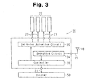
- the transmitter 15 comprises a controller 26 which includes a microcomputer.
- the controller 26 includes, for example, a central processing unit (CPU), read only memory (ROM), and random access memory (RAM).
- a pressure sensor 27 measures the air pressure of the tire 14 and outputs tire air pressure data, which has been obtained through the measurement, to a controller 26.
- the controller 26 outputs the inputted air pressure data to a transmission circuit 28.
- the transmission circuit 28 functions as determination signal transmitting means or a determination signal transmitting device which encodes and modulates air pressure data received from the controller 26, generates a determination signal, and wirelessly transmits the determination signal via a transmission antenna 29 two or more times in a fixed time period.
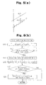
- a measured air pressure is converted into an 8-bit code and is analog modulated before transmission. Therefore, as shown in Fig. 5(a), an actual air pressure Ar1 indicates each predetermined range Ar2 of consecutive air pressures in an encoded state.
- the predetermined range Ar2 is the minimum resolution indicating an air pressure Ar1 during transmission and reception.
- the minimum resolution is converted into a tire air pressure of 2.5 kPa.
- a trigger signal detection circuit 30 functions as trigger signal detecting means or a trigger signal detecting device which detects a trigger signal from the corresponding initiator 22 via a trigger signal reception antenna 31.
- the trigger signal detection circuit 30 notifies the controller 26 of the detection.
- the controller 26 causes a pressure sensor 27 to measure an air pressure.
- the transmitter 15 has a battery 32 and is activated by power supplied from the battery 32.
- each receiver 16 comprises a controller 33, which includes a microcomputer for processing reception data, and a reception circuit 34.
- the controller 33 includes, e.g., a CPU, ROM, and RAM.
- the reception circuit 34 functions as receiving means or a receiving device which receives, via the reception antenna 18, two or more determination signals including air pressure data transmitted from the transmitters 15.
- the reception circuit 34 demodulates and decodes the determination signal, and then sends the signal to the controller 33.
- the controller 33 functions as determining means or a determining device which determines whether there is a match between, for example, the first two of determination signals having been received from the reception circuit 34. When the two determination signals match with each other, the controller 33 locates the position of the tire 14 based on which initiator 22 has been instructed to transmit the trigger signal, and processes air pressure data, which is included in the determination signals, as valid data. The controller 33 causes the display 20 to show data of the air pressure.
- the receiver 16 comprises an initiator actuation circuit 35 for driving the initiators 22 corresponding to the transmitters 15.
- the initiator actuation circuit 35 is controlled by the controller 33 and wirelessly transmits trigger signals from the initiators 22, each of which corresponds to one of the transmitters 15, at regular time intervals (for example, every 15 seconds).
- the transmission timing of each initiator 22 is adjusted such that each initiator 22 wirelessly transmits the trigger signal at a timing that differs from that of the other initiators 22. Therefore, two or more of the initiators 22 do not wirelessly transmit trigger signals simultaneously.
- At least a radio wave in the long wavelength range (LF: 30 kHz to 300 kHz) is used as the trigger signal. This is under the assumption that a reflected wave may be generated when the vehicle 12 reflects the trigger signal and so on. That is, there is less susceptibility to interference caused by reflected waves from the vehicle 12 when the trigger signal is in the long wavelength range. Therefore, the trigger signal reception antenna 31 of the transmitter 15 receives the trigger signal at any rotation angle of the tire 14. Accordingly, data representing the condition of the tire 14 can be transferred between the transmitter 15 and the receiver 16 even when the vehicle 12 is moving.
- LF 30 kHz to 300 kHz
- the output of the initiator actuation circuit 35 can be easily restricted when the trigger signal is in the long wavelength range.
- the output of the initiator actuation circuit 35 can be restricted to enable detection of only the trigger signal of the transmitter 15 that corresponds to predetermine one of the initiators 22. Therefore, for example, only the corresponding transmitter 15 detects the trigger signal transmitted from the initiator 22. Accordingly, when the receiver 16 receives a determination signal transmitted from the transmitter 15 corresponding to a trigger signal via the reception antenna 18, the tire 14 incorporating the transmitter 15 can be located with ease.
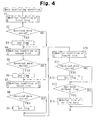
- step S1 the condition of the first tire 14, which includes an air pressure, is monitored.
- the tires 14 are identified as first to fourth tires.
- step S2 on the assumption that data received by the receiver 16 is identical to data transmitted from the transmitter 15 of the first tire 14, it is determined whether the reception data has been processed validly. When the reception data has been processed validly, the process advances to S3. When the reception data has not been processed validly, the process advances to S4. In S3, a flag is set in a predetermined area of the RAM of the controller 33 to indicate the completion of valid processing.
- step S4 the condition of the second tire 14, which includes an air pressure, is monitored.
- S5 and S6 as in S2 and S3, it is determined whether reception data has been processed validly.
- a flag is set in the predetermined area of the RAM.
- S7 to S9 as in S1 to S3 and S4 to S6, the condition of the third tire 14 is monitored, it is determined whether reception data has been processed validly, and a flag is set when the data has been processed validly.
- S10 to S12 the condition of the fourth tire 14 is monitored, it is determined whether reception data has been processed validly, and a flag is set when the data has been processed validly.
- S13 it is determined whether data with no flag is present in the predetermined area of the RAM of the controller 33.
- S14 a series of operations including the monitoring of condition is performed again for the tire 14 corresponding to the data. After valid flags are set for all the tires 14, the predetermined area is cleared in preparation for subsequent processing.
- a trigger signal is wirelessly transmitted from any one of the initiators 22 corresponding to one of the first to fourth tires 14. Then, in the transmitter 15 of the tire 14, the trigger signal is detected by the trigger signal detection circuit 30 and the air pressure of the tire 14 is measured by the pressure sensor 27 under the control of the controller 26 of the transmitter 15. Then, air pressure data obtained through the measurement is outputted to the transmission circuit 28 via the controller 26. In the transmission circuit 28, the air pressure data from the controller 26 is encoded and modulated, so that a determination signal is generated. The determination signal is wirelessly transmitted from the transmission antenna 29 two or more times in a fixed time period.
- the reception circuit 34 of the receiver 16 has received two or more determination signals from the transmission circuit 28.
- the RAM of the controller 33 stores, for example, data of the first two of the received determination signals.
- the two stored determination signals are compared with each other and it is determined whether a variation between the determination signals (error range) is a predetermined resolution or less (for example, ⁇ 1 resolution from the first signal). That is, when two or more data are received in quite a short time (e.g., 30 mm/sec) from the same tire, a variation between determination signals is generally a resolution of 1 or less.
- the process advances to S19.
- the process goes back to the main routine of Fig. 4 and the subsequent operation is performed.
- the position of the tire 14 is located based on which initiator 22 is instructed to transmit a trigger signal, and air pressure data included in the determination signal is processed as valid data. That is, data of the air pressure is shown on the display 20. Thereafter, the process goes back to the main routine of Fig. 4 and the subsequent operation is performed.
- the tire condition monitoring apparatus of the present embodiment it is determined whether a variation between two determination signals is within the predetermined range of resolutions.
- the two determination signals include tire information about air pressure data and so on transmitted from the transmission circuit 28 of the transmitter 15.
- the variation is within the predetermined range of resolutions, the position of the tire 14 is located and the tire information is processed as valid information.
- This configuration permits tire condition monitoring to be started quickly.
- Two or more determination signals including tire information are transmitted for each of the tires 14 in a fixed time period, and it is determined whether a variation between two of the determination signals is within the predetermined range of resolutions.
- the first embodiment has the following advantages.
- a specific ID code is registered beforehand as identification information in the ROM or RAM of an internal memory in a controller 26 of each transmitter 15. According to the flowchart of Fig. 6, the tires 14 are monitored in almost a similar manner to the first embodiment.
- a trigger signal is wirelessly transmitted from any one of initiators 22 and is detected by a trigger signal detection circuit 30 of the corresponding transmitter 15. Then, in the corresponding transmitter 15, the air pressure of the tire 14 is measured by a pressure sensor 27 under the control of the controller 26. Further, an ID code is read from the internal memory of the controller 26, and air pressure data obtained through the measurement and data including the ID code are outputted to a transmission circuit 28. In the transmission circuit 28, data from the controller 26 is encoded and modulated, so that a determination signal including the air pressure data and the ID code is generated, and the determination signal is wirelessly transmitted from a transmission antenna 29 two or more times in a fixed time period.
- S22 it is determined whether a reception circuit 34 of a receiver 16 has received the two or more determination signals from the transmission circuit 28.
- the first two of the received determination signals are stored in the RAM of a controller 33 in S23.
- the ID codes of the stored two determination signals are compared with each other to determine whether the ID codes match with each other.
- the process advances to S26 and the position of the tire 14 is located based on the ID codes and the air pressure data is processed as valid data.
- the second embodiment can obtain almost the same advantages as the items (1) and (2) of the first embodiment.
- a third embodiment according to the present invention will be described below in accordance with the flowchart of Fig. 7. The differences from the first embodiment will mainly be discussed.
- a controller 26 of each transmitter 15 functions as storage means or a storage device for storing identification information of the corresponding tire 14. Specific ID codes are registered beforehand as identification information in the ROM or RAM of an internal memory of the controller 26.
- Initiators 22 corresponding to the transmitters 15 function as, in addition to trigger signal transmitting means or devices, instruction signal transmitting means or devices for wirelessly transmitting an instruction signal for instructing each transmitter 15 to transmit an identification signal based on the ID code stored in the internal memory of the controller 26.
- a transmission circuit 28 of each transmitter 15 functions as identification signal transmitting means or an identification signal transmitting device for wirelessly transmitting an identification signal, in response to the instruction signal from the corresponding initiator 22, based on the ID code together with data of an air pressure measured by a pressure sensor 27.
- a reception circuit 34 of a receiver 16 functions as receiving means or a receiving device for receiving an air identification signal including air pressure data transmitted from each transmission circuit 28.
- a controller 33 of the receiver 16 functions as determining means or a determining device which determines whether there is a match between the identification signal having been received by the reception circuit 34 and the identification signal having been instructed to any of the initiators 22. When there is a match, the position of the tire 14 is located and the air pressure data is processed as valid data. Then, under the control of the controller 33 of the receiver 16, the tires 14 are monitored according to the flowchart of Fig. 7.
- an instruction signal such as a trigger signal for instructing an identification signal to be transmitted is wirelessly transmitted from any one of the initiators 22.
- the instruction signal is detected by a trigger signal detection circuit 30.
- the air pressure of the tire 14 is measured by a pressure sensor 27.
- the ID code is read from the internal memory of the controller 26, and air pressure data measured by the pressure sensor 27 and data including the ID code are outputted to the transmission circuit 28.
- data from the controller 26 is encoded and modulated, so that transmission data including the air pressure data and the ID code is generated, and the data is wirelessly transmitted from a transmission antenna 29.
- S28 it is determined whether the reception circuit 34 of the receiver 16 has received the data from the transmission circuit 28.
- the received data is stored in the RAM of the controller 33 in S29.
- S30 and S31 a comparison is made between the ID code included in the stored reception data and the ID code instructed by the controller 33 to the initiator 22, and it is determined whether the ID codes match with each other.
- the process advances to S32.
- the ID codes do not match with each other, the process advances to S33.
- the position of the tire 14 is located based on the matching ID codes and the air pressure data included in the reception data is processed as valid data. That is, data of the air pressure is shown on a display 20. Therefore, the process goes back to the main routine of Fig. 4 and the subsequent operation is performed. Meanwhile, in S33, it is determined whether the number of mismatches of the ID codes reaches the predetermined number of times (e.g., two) for each trigger signal. When the number of mismatches reaches the predetermined number of times, the process advances to S34. When the number of mismatches does not reach the predetermined number of times, the process goes back to the main routine of Fig. 4 and the subsequent operation is performed.
- the predetermined number of times e.g., two
- the third embodiment provides the following advantage.
- the minimum resolution may be set at, for example, 2 kPa other than 2.5 kPa.
- the number of mismatches may be determined and abnormality processing such as the display of an abnormality may be performed.
- the abnormality may be indicated by a sound.
- a speaker mounted on the vehicle 12 may be used as an informing device.
- the air pressure information transmitted from each transmitter 15 may be data specifically indicating the value of the air pressure or data that simply indicates that the air pressure is included in a tolerable range.
- a temperature sensor may be provided in each transmitter 15 and air pressure data and temperature data in the corresponding tire 14 may be wirelessly transmitted from the transmitter 15 as data indicating tire condition.
- the present invention may be applied to two-wheeled vehicles, such as bicycles and motor cycles, multi-wheeled busses, multi-wheeled towed vehicles and industrial vehicles such as forklifts.
- two-wheeled vehicles such as bicycles and motor cycles, multi-wheeled busses, multi-wheeled towed vehicles and industrial vehicles such as forklifts.
- the present invention is applied to a trailer, the receiver 16 and the display 20 are provided in the tractor.
Landscapes
- Engineering & Computer Science (AREA)
- Mechanical Engineering (AREA)
- Computer Networks & Wireless Communication (AREA)
- Measuring Fluid Pressure (AREA)
- Arrangements For Transmission Of Measured Signals (AREA)
Applications Claiming Priority (1)
| Application Number | Priority Date | Filing Date | Title |
|---|---|---|---|
| JP2004247156A JP2006062516A (ja) | 2004-08-26 | 2004-08-26 | タイヤ状態監視装置,送信装置及び受信装置 |
Publications (3)
| Publication Number | Publication Date |
|---|---|
| EP1630009A2 true EP1630009A2 (fr) | 2006-03-01 |
| EP1630009A3 EP1630009A3 (fr) | 2006-11-02 |
| EP1630009B1 EP1630009B1 (fr) | 2009-02-11 |
Family
ID=35467409
Family Applications (1)
| Application Number | Title | Priority Date | Filing Date |
|---|---|---|---|
| EP05102114A Expired - Fee Related EP1630009B1 (fr) | 2004-08-26 | 2005-03-17 | Emetteur et récepteur pour appareil de surveillance de condition de pneumatique |
Country Status (4)
| Country | Link |
|---|---|
| US (1) | US7253726B2 (fr) |
| EP (1) | EP1630009B1 (fr) |
| JP (1) | JP2006062516A (fr) |
| DE (1) | DE602005012651D1 (fr) |
Cited By (3)
| Publication number | Priority date | Publication date | Assignee | Title |
|---|---|---|---|---|
| WO2009094900A1 (fr) * | 2008-01-22 | 2009-08-06 | Suzhou Sate Auto Electronic Co., Ltd. | Procédé pour apparier un émetteur de détection extérieur et un moniteur central dans un système de surveillance de pression des pneumatiques |
| CN106626993A (zh) * | 2016-12-22 | 2017-05-10 | 深圳市车生活科技有限公司 | 一种tpms轮胎检测系统及方法 |
| CN110121435A (zh) * | 2017-12-05 | 2019-08-13 | 太平洋工业株式会社 | 发送器及轮胎状态监视装置 |
Families Citing this family (28)
| Publication number | Priority date | Publication date | Assignee | Title |
|---|---|---|---|---|
| DE10347301B4 (de) * | 2003-10-08 | 2007-12-13 | Infineon Technologies Ag | Schaltung mit einem Bus mit mehreren Empfängern |
| DE102004018827B4 (de) * | 2004-04-19 | 2006-06-29 | Siemens Ag | Vorrichtung und Verfahren zur Ermittlung der Radposition von Rädern eines Radfahrzeuges |
| JP4812432B2 (ja) * | 2006-01-10 | 2011-11-09 | 株式会社ブリヂストン | タイヤ点検装置、タイヤ点検システム及びタイヤ点検方法 |
| JP4609355B2 (ja) * | 2006-03-22 | 2011-01-12 | 株式会社日本自動車部品総合研究所 | タイヤ空気圧検出装置 |
| EP1849627B1 (fr) * | 2006-04-26 | 2012-03-14 | austriamicrosystems AG | Procédé de transmission de données pour déterminer la position d'une roue dans un système de surveillance de pression des pneumatiques |
| JP4858034B2 (ja) * | 2006-09-19 | 2012-01-18 | 株式会社デンソー | 車輪位置検出装置およびそれを備えたタイヤ空気圧検出装置 |
| DE102006055878B4 (de) * | 2006-11-23 | 2020-12-03 | Huf Baolong Electronics Bretten Gmbh | Verfahren zum Zuordnen von Identifikationscodes in Funksignalen von Reifendruckkontrolleinrichtungen an Fahrzeugrädern zu deren Position und zum Durchführen des Verfahrens ausgestattetes Fahrzeug |
| GB0623802D0 (en) * | 2006-11-29 | 2007-01-10 | Brown Duncan | An arrangement of interconnected devices or system to indicate loading state or overload of the axles on a vehicle |
| US20090016728A1 (en) * | 2007-02-01 | 2009-01-15 | Marquee, Inc. | Method and system for pairing a remote control with a device |
| FR2915927B1 (fr) * | 2007-05-09 | 2010-05-21 | Ldl Technology | Procede de mise en position des capteurs de roues jumelees d'un vehicule. |
| TWI382167B (zh) * | 2008-11-18 | 2013-01-11 | Orange Electronic Co Ltd | A tire pressure detecting device capable of detecting a carrier wave and a method thereof |
| EP2360290A1 (fr) * | 2010-02-11 | 2011-08-24 | Applied Materials, Inc. | Procédé de production d'une couche ITO et système de pulvérisation |
| US8528393B2 (en) * | 2010-02-26 | 2013-09-10 | Schrader Electronics Ltd. | Wheel position determination using revolution counter |
| JP5803733B2 (ja) * | 2012-02-23 | 2015-11-04 | 株式会社デンソー | 車輪位置検出機能を備えたタイヤ空気圧検出装置 |
| US9469166B2 (en) * | 2012-06-06 | 2016-10-18 | Continental Automotive Systems, Inc. | Apparatus and method for tire localization |
| EP2851215B9 (fr) * | 2012-07-24 | 2017-09-20 | The Yokohama Rubber Co., Ltd. | Dispositif de transmission, système de surveillance d'état de pneu, et ensemble de pneu |
| JP2014080176A (ja) | 2012-09-25 | 2014-05-08 | Tokai Rika Co Ltd | タイヤ位置判定システム |
| JP6098106B2 (ja) * | 2012-10-23 | 2017-03-22 | オムロン株式会社 | センサシステムおよび通信装置 |
| JP2014121982A (ja) | 2012-12-21 | 2014-07-03 | Tokai Rika Co Ltd | タイヤ位置判定システム |
| JP2014128982A (ja) | 2012-12-27 | 2014-07-10 | Tokai Rika Co Ltd | タイヤ位置判定システム |
| JP2015013635A (ja) | 2012-12-27 | 2015-01-22 | 株式会社東海理化電機製作所 | タイヤ位置判定システム |
| JP2015101208A (ja) * | 2013-11-25 | 2015-06-04 | 株式会社東海理化電機製作所 | タイヤ位置判定システム |
| DE102016214865A1 (de) * | 2016-08-10 | 2018-02-15 | Continental Automotive Gmbh | Elektronische Radeinheit für ein Fahrzeugrad, sowie Verfahren zum Betreiben einer derartigen elektronischen Radeinheit |
| DE102016120457B4 (de) * | 2016-10-26 | 2020-12-03 | Huf Baolong Electronics Bretten Gmbh | Verfahren zum Betreiben einer Reifendrucküberwachungseinheit sowie Reifendrucküberwachungssystem |
| DE102016225481A1 (de) | 2016-12-19 | 2018-06-21 | Continental Automotive Gmbh | Verfahren zur funktechnischen Optimierung einer Radüberwachung in einem Fahrzeug, Radüberwachungssystem eines Fahrzeuges sowie elektronische Radeinheit und Steuereinrichtung für ein derartiges Radüberwachungssystem |
| WO2019111329A1 (fr) * | 2017-12-05 | 2019-06-13 | 太平洋工業 株式会社 | Émettteur |
| KR102219872B1 (ko) * | 2018-10-01 | 2021-02-24 | 다이헤요 고교 가부시키가이샤 | 타이어 상태 감시 시스템, 송신기 및 수신기 |
| CN114179571B (zh) * | 2021-12-22 | 2022-10-21 | 奇瑞汽车股份有限公司 | 胎压传感器的定位方法、装置及车辆 |
Citations (1)
| Publication number | Priority date | Publication date | Assignee | Title |
|---|---|---|---|---|
| DE19632150A1 (de) | 1996-08-09 | 1998-02-12 | Telefunken Microelectron | Verfahren zur Kontrolle des Luftdrucks in den Reifen von Kraftfahrzeugrädern |
Family Cites Families (8)
| Publication number | Priority date | Publication date | Assignee | Title |
|---|---|---|---|---|
| DE4205911A1 (de) | 1992-02-26 | 1993-09-02 | Uwatec Ag | Kontrollvorrichtung fuer den luftdruck von luftbereiften fahrzeugraedern |
| US5483827A (en) * | 1994-06-03 | 1996-01-16 | Computer Methods Corporation | Active integrated circuit transponder and sensor apparatus for sensing and transmitting vehicle tire parameter data |
| US5500065A (en) * | 1994-06-03 | 1996-03-19 | Bridgestone/Firestone, Inc. | Method for embedding a monitoring device within a tire during manufacture |
| US6486773B1 (en) * | 1998-09-10 | 2002-11-26 | Schrader-Bridgeport International, Inc. | Method for communicating data in a remote tire pressure monitoring system |
| US7015801B1 (en) | 2000-10-13 | 2006-03-21 | Trw Inc. | Vehicle-controlled tire condition sensor communication utilizing fixed tire identification |
| JP2003080910A (ja) | 2001-06-28 | 2003-03-19 | Pacific Ind Co Ltd | タイヤ状態監視装置 |
| GB0203230D0 (en) | 2002-02-12 | 2002-03-27 | Lucas Industries Ltd | Tyre pressure monitor system |
| JP2004203225A (ja) * | 2002-12-25 | 2004-07-22 | Pacific Ind Co Ltd | タイヤ状態監視装置 |
-
2004
- 2004-08-26 JP JP2004247156A patent/JP2006062516A/ja active Pending
-
2005
- 2005-02-28 US US11/069,813 patent/US7253726B2/en not_active Expired - Fee Related
- 2005-03-17 DE DE602005012651T patent/DE602005012651D1/de not_active Expired - Lifetime
- 2005-03-17 EP EP05102114A patent/EP1630009B1/fr not_active Expired - Fee Related
Patent Citations (1)
| Publication number | Priority date | Publication date | Assignee | Title |
|---|---|---|---|---|
| DE19632150A1 (de) | 1996-08-09 | 1998-02-12 | Telefunken Microelectron | Verfahren zur Kontrolle des Luftdrucks in den Reifen von Kraftfahrzeugrädern |
Cited By (4)
| Publication number | Priority date | Publication date | Assignee | Title |
|---|---|---|---|---|
| WO2009094900A1 (fr) * | 2008-01-22 | 2009-08-06 | Suzhou Sate Auto Electronic Co., Ltd. | Procédé pour apparier un émetteur de détection extérieur et un moniteur central dans un système de surveillance de pression des pneumatiques |
| CN106626993A (zh) * | 2016-12-22 | 2017-05-10 | 深圳市车生活科技有限公司 | 一种tpms轮胎检测系统及方法 |
| CN110121435A (zh) * | 2017-12-05 | 2019-08-13 | 太平洋工业株式会社 | 发送器及轮胎状态监视装置 |
| CN110121435B (zh) * | 2017-12-05 | 2020-12-29 | 太平洋工业株式会社 | 发送器及轮胎状态监视装置 |
Also Published As
| Publication number | Publication date |
|---|---|
| US7253726B2 (en) | 2007-08-07 |
| EP1630009A3 (fr) | 2006-11-02 |
| DE602005012651D1 (de) | 2009-03-26 |
| EP1630009B1 (fr) | 2009-02-11 |
| JP2006062516A (ja) | 2006-03-09 |
| US20060055524A1 (en) | 2006-03-16 |
Similar Documents
| Publication | Publication Date | Title |
|---|---|---|
| EP1630009B1 (fr) | Emetteur et récepteur pour appareil de surveillance de condition de pneumatique | |
| US7212105B2 (en) | Transmitter for tire condition monitoring apparatus | |
| EP1336511B1 (fr) | Emetteur pour un appareil de surveillance de condition de pneumatique et appareil avec l'émetteur | |
| US6983649B2 (en) | Tire condition monitoring apparatus | |
| US6885292B2 (en) | Tire condition monitoring apparatus | |
| US20040172179A1 (en) | Transmitter of tire condition monitoring apparatus and tire condition monitoring apparatus | |
| US7750798B2 (en) | Wheel position detecting device that verifies accuracy of detection using trigger signal reception strength and tire air pressure detecting device including the same | |
| JP2003175711A (ja) | タイヤ状態監視装置 | |
| US6937145B2 (en) | Transmitter for tire condition monitoring apparatus and the tire condition monitoring apparatus | |
| EP1428693B1 (fr) | Transpondeur pour appareil de surveillance de condition de pneumatique | |
| US6999861B2 (en) | Tire status monitoring apparatus and receiver therefor | |
| JP4876887B2 (ja) | 車輪位置検出装置およびそれを備えたタイヤ空気圧検出装置 | |
| US20040135681A1 (en) | Tire condition monitoring apparatus | |
| US7215243B2 (en) | Tire pressure characterization method and key fob | |
| JP4144521B2 (ja) | タイヤ盗難検知装置 | |
| US20020171539A1 (en) | Code learning device of tire pressure monitor | |
| US8296006B2 (en) | Tire pressure monitoring device | |
| EP1419906A1 (fr) | Méthode de transmission pour un émetteur et méthode de traitement pour un récepteur | |
| US20250296393A1 (en) | Method for detecting a foreign object under a motor vehicle | |
| KR20090005198U (ko) | 타이어 공기압 측정용 압력센서 및 이를 구비한 타이어공기압 모니터링 시스템 |
Legal Events
| Date | Code | Title | Description |
|---|---|---|---|
| PUAI | Public reference made under article 153(3) epc to a published international application that has entered the european phase |
Free format text: ORIGINAL CODE: 0009012 |
|
| AK | Designated contracting states |
Kind code of ref document: A2 Designated state(s): AT BE BG CH CY CZ DE DK EE ES FI FR GB GR HU IE IS IT LI LT LU MC NL PL PT RO SE SI SK TR |
|
| AX | Request for extension of the european patent |
Extension state: AL BA HR LV MK YU |
|
| PUAL | Search report despatched |
Free format text: ORIGINAL CODE: 0009013 |
|
| AK | Designated contracting states |
Kind code of ref document: A3 Designated state(s): AT BE BG CH CY CZ DE DK EE ES FI FR GB GR HU IE IS IT LI LT LU MC NL PL PT RO SE SI SK TR |
|
| AX | Request for extension of the european patent |
Extension state: AL BA HR LV MK YU |
|
| 17P | Request for examination filed |
Effective date: 20070112 |
|
| 17Q | First examination report despatched |
Effective date: 20070301 |
|
| AKX | Designation fees paid |
Designated state(s): DE FR GB |
|
| GRAP | Despatch of communication of intention to grant a patent |
Free format text: ORIGINAL CODE: EPIDOSNIGR1 |
|
| RTI1 | Title (correction) |
Free format text: TIRE CONDITION MONITORING APPARATUS, TRANSMITTER AND RECEIVER |
|
| GRAS | Grant fee paid |
Free format text: ORIGINAL CODE: EPIDOSNIGR3 |
|
| GRAA | (expected) grant |
Free format text: ORIGINAL CODE: 0009210 |
|
| AK | Designated contracting states |
Kind code of ref document: B1 Designated state(s): DE FR GB |
|
| REG | Reference to a national code |
Ref country code: GB Ref legal event code: FG4D |
|
| REF | Corresponds to: |
Ref document number: 602005012651 Country of ref document: DE Date of ref document: 20090326 Kind code of ref document: P |
|
| PLBE | No opposition filed within time limit |
Free format text: ORIGINAL CODE: 0009261 |
|
| STAA | Information on the status of an ep patent application or granted ep patent |
Free format text: STATUS: NO OPPOSITION FILED WITHIN TIME LIMIT |
|
| 26N | No opposition filed |
Effective date: 20091112 |
|
| REG | Reference to a national code |
Ref country code: FR Ref legal event code: PLFP Year of fee payment: 11 |
|
| PGFP | Annual fee paid to national office [announced via postgrant information from national office to epo] |
Ref country code: DE Payment date: 20150310 Year of fee payment: 11 |
|
| PGFP | Annual fee paid to national office [announced via postgrant information from national office to epo] |
Ref country code: FR Payment date: 20150309 Year of fee payment: 11 Ref country code: GB Payment date: 20150311 Year of fee payment: 11 |
|
| REG | Reference to a national code |
Ref country code: DE Ref legal event code: R119 Ref document number: 602005012651 Country of ref document: DE |
|
| GBPC | Gb: european patent ceased through non-payment of renewal fee |
Effective date: 20160317 |
|
| REG | Reference to a national code |
Ref country code: FR Ref legal event code: ST Effective date: 20161130 |
|
| PG25 | Lapsed in a contracting state [announced via postgrant information from national office to epo] |
Ref country code: GB Free format text: LAPSE BECAUSE OF NON-PAYMENT OF DUE FEES Effective date: 20160317 Ref country code: FR Free format text: LAPSE BECAUSE OF NON-PAYMENT OF DUE FEES Effective date: 20160331 Ref country code: DE Free format text: LAPSE BECAUSE OF NON-PAYMENT OF DUE FEES Effective date: 20161001 |