EP1630308A2 - Elément de regard préfabriqué en béton - Google Patents
Elément de regard préfabriqué en béton Download PDFInfo
- Publication number
- EP1630308A2 EP1630308A2 EP20050012406 EP05012406A EP1630308A2 EP 1630308 A2 EP1630308 A2 EP 1630308A2 EP 20050012406 EP20050012406 EP 20050012406 EP 05012406 A EP05012406 A EP 05012406A EP 1630308 A2 EP1630308 A2 EP 1630308A2
- Authority
- EP
- European Patent Office
- Prior art keywords
- prefabricated part
- load
- transfer element
- part according
- shaft
- Prior art date
- Legal status (The legal status is an assumption and is not a legal conclusion. Google has not performed a legal analysis and makes no representation as to the accuracy of the status listed.)
- Withdrawn
Links
Images


Classifications
-
- E—FIXED CONSTRUCTIONS
- E03—WATER SUPPLY; SEWERAGE
- E03F—SEWERS; CESSPOOLS
- E03F5/00—Sewerage structures
- E03F5/02—Manhole shafts or other inspection chambers; Snow-filling openings; accessories
-
- B—PERFORMING OPERATIONS; TRANSPORTING
- B28—WORKING CEMENT, CLAY, OR STONE
- B28B—SHAPING CLAY OR OTHER CERAMIC COMPOSITIONS; SHAPING SLAG; SHAPING MIXTURES CONTAINING CEMENTITIOUS MATERIAL, e.g. PLASTER
- B28B21/00—Methods or machines specially adapted for the production of tubular articles
- B28B21/56—Methods or machines specially adapted for the production of tubular articles incorporating reinforcements or inserts
- B28B21/563—Gaskets
-
- E—FIXED CONSTRUCTIONS
- E02—HYDRAULIC ENGINEERING; FOUNDATIONS; SOIL SHIFTING
- E02D—FOUNDATIONS; EXCAVATIONS; EMBANKMENTS; UNDERGROUND OR UNDERWATER STRUCTURES
- E02D29/00—Independent underground or underwater structures; Retaining walls
- E02D29/12—Manhole shafts; Other inspection or access chambers; Accessories therefor
- E02D29/14—Covers for manholes or the like; Frames for covers
- E02D29/149—Annular gaskets
-
- F—MECHANICAL ENGINEERING; LIGHTING; HEATING; WEAPONS; BLASTING
- F16—ENGINEERING ELEMENTS AND UNITS; GENERAL MEASURES FOR PRODUCING AND MAINTAINING EFFECTIVE FUNCTIONING OF MACHINES OR INSTALLATIONS; THERMAL INSULATION IN GENERAL
- F16L—PIPES; JOINTS OR FITTINGS FOR PIPES; SUPPORTS FOR PIPES, CABLES OR PROTECTIVE TUBING; MEANS FOR THERMAL INSULATION IN GENERAL
- F16L21/00—Joints with sleeve or socket
- F16L21/02—Joints with sleeve or socket with elastic sealing rings between pipe and sleeve or between pipe and socket, e.g. with rolling or other prefabricated profiled rings
- F16L21/03—Joints with sleeve or socket with elastic sealing rings between pipe and sleeve or between pipe and socket, e.g. with rolling or other prefabricated profiled rings placed in the socket before connection
-
- F—MECHANICAL ENGINEERING; LIGHTING; HEATING; WEAPONS; BLASTING
- F16—ENGINEERING ELEMENTS AND UNITS; GENERAL MEASURES FOR PRODUCING AND MAINTAINING EFFECTIVE FUNCTIONING OF MACHINES OR INSTALLATIONS; THERMAL INSULATION IN GENERAL
- F16L—PIPES; JOINTS OR FITTINGS FOR PIPES; SUPPORTS FOR PIPES, CABLES OR PROTECTIVE TUBING; MEANS FOR THERMAL INSULATION IN GENERAL
- F16L49/00—Connecting arrangements, e.g. joints, specially adapted for pipes of brittle material, e.g. glass, earthenware
- F16L49/02—Joints with a sleeve or socket
-
- E—FIXED CONSTRUCTIONS
- E03—WATER SUPPLY; SEWERAGE
- E03F—SEWERS; CESSPOOLS
- E03F5/00—Sewerage structures
- E03F5/02—Manhole shafts or other inspection chambers; Snow-filling openings; accessories
- E03F2005/028—Sealing joints between manhole segments
Definitions
- the invention relates to a manhole precast concrete with the features of the preamble of claim 1.
- Manhole structures are assembled in the excavation pit from manhole components. These are the following different components: Manhole bases with connection openings for pipelines, which have a spigot end at the upper end, further manhole rings, which have a bell socket end and a spigot at the top, and chess necks, cones or the like, the bottom with a corresponding bell mouth end are provided.
- a staggered stacking of manhole components on top of each other on the storage space is possible only with difficulty because it must always be ensured that the manhole components do not stand up with the located in the region of the outer ring surface, there protruding plastic parts, with the risk of crushing the latter punctually become.
- Another disadvantage is that the plastic parts consist of such a creeping material whose creeping properties can not be stopped in principle, so that after a certain time the support device is compressed so far with the plastic parts that the stacked manhole components get concrete contact and Point loads occur. This is further facilitated by the fact that the individual plastic parts are embedded in concrete with a relatively large foot in the region of the outer annular surface of the bell socket end.
- the invention has for its object od manhole structures made of concrete.
- the like Of the aforementioned type, in which the above-described disadvantages are eliminated, the use of materials and the cost be reduced and created at least one support device and arranged so that it placed protected and thus the manhole section is protected.
- the object is achieved in a shaft precast concrete of the type mentioned according to the invention by the features in claim 1.
- the at least one load transfer element of the support device is arranged on the inner annular surface of the bell socket end of the manhole component, the load transfer element is protected from damage and dirt inside the bell socket end arranged.
- annular design thereby at the same time when joining the manhole components a joint gap, which is present between the inner annular surface of the upper and the annular surface of the spigot end of the lower manhole part, closed by the at least one load transfer element.
- the cross-section and the material properties of the at least one load-transfer element can be determined so that under scheduled loading of the manhole and thus formed shaft structures formed a permanent change in shape of the at least one load transfer element and thus increase the contact surfaces and no undue stress on the manhole components arise.
- the enlargement of the bearing surfaces due to the permanent compression of the at least one load transfer element takes place both in the circumferential direction and transversely thereto in the width of the load transfer element. As a result, the surface pressure does not increase further.
- impermissible stresses could be the surface pressure on the concrete at the bearing surfaces as well as bending and shear stresses in the concrete.
- the at least one load transfer element is designed so that at the maximum force, the load transfer element approximately with its entire bearing surface on the Ring surface rests on the tip end of a subsequent lower manhole part and thus the vertical force is transmitted evenly. After a single strong load the load transfer element does not spring back and deforms not further, so that any concrete contact and point loads are not to be feared.
- the support device may have at least one compression seal in addition to the at least one load transfer element.
- This can be formed from an elastomer and elastically deformable.
- the at least one compression seal may be a separate component separated from the at least one load-transfer element. Then there are two different components, of which, for example, the at least one load-transfer element, which is plastically deformable, has a greater hardness than the elastically deformable compression seal.
- the at least one load transfer element and the at least one compression seal can also form an integral sealing element.
- the compression seal is elastically deformable, while the at least one load-transfer element is plastically deformable.
- the one-piece sealing element can be produced by coextruding two different materials in an injection process in which components of different hardness are inseparably combined to form a unit. This is inexpensive.
- a one-piece sealing element moreover, the number of individual components is reduced and thus also achieved a simplification in the manufacture of the shaft precast and thereby formed shaft structures. Both in the two-part and in the one-piece design can be particularly adapted to the requirements of the at least one load-transfer element whose properties.
- the invention further provides a method for producing a manhole prefabricated part according to claims 48 and 49.
- the invention further provides a support device for manhole components of this type, wherein the support means is characterized by the formation thereof with the features in one or more of claims 1 to 49, which contain the support features concerned.
- the support means may be formed depending on the design alone of at least one load transfer element, especially if this is designed so that it is also sealing in addition to the load transfer and thus can seal the annular gap formed between the annular surfaces one above the other sitting manure. This is the case, for example, in particular in the case of at least one load-transfer element, as defined in claims 26 to 33.
- the at least one load transfer element is at least partially formed from an elastomer, wherein at least the region of the support lips is elastically deformable, thereby also achieving a corresponding sealing effect.
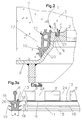
- Fig. 1 to 3b is schematically a first embodiment of manhole precast concrete or the like. for manhole structures 7 to be formed by stacking. Shown is the cross section of a part of the joining of two stacked manure sections 3, of which the lower manhole section 3 z. B. may represent a manhole ring or a lower part, which has a spigot end 22 with upper annular surface 6 at the upper end, which extends inside.
- the upper finished part 3 located above, for example, also consists of a manhole ring or a cone. This has a bell socket end 5, which is formed from an axially downwardly projecting collar 12 with outer annular surface 9 and an axially spaced from the outer annular surface 9 upwardly recessed inner annular surface 2.
- the at least one load-transfer element 1 of the support device 11 is such that with vertical load of the shaft precast part 3 and support this via the load transfer element 1 at the bottom manhole part 3 such a change in shape of the load transfer element 1, the at least the support surface 4 and support surface of this, u , U. but also an enlargement of the inner surface 13, brought about.
- the load transfer element 1 is held on the inner annular surface 2 of the bell socket end 5, with particular advantage z.
- Example, characterized in that the load transfer element 1 is carried out by at least one anchoring part 8 of the load transfer element 1 done in the manufacture of the shaft precast element 3 concreting.
- the load transfer element 1 is thus concreted in by means of the at least one anchoring part 8 in the upper shaft precast part 3 and there on the inner annular surface 2 and firmly anchored.
- the at least one anchoring part 8 is integral with the remaining part of the load transfer element 1 and serves only the holder.
- the upper annular surface 6 at the spigot end 22 has production-related unevenness.
- the load transfer element 1 with its lower support surface 4 only partially rest on the annular surface 6.
- the at least one anchoring part 8 is z. B. in cross-section relatively thin.
- the inner joint gap between the annular surfaces 2 and 6 is closed by the at least one load transfer element 1 in the annular peripheral design.
- the cross-section and the material properties of the load transfer element 1 are selected such that at vertical loading of the manhole panels 3 by weight and / or traffic load and / or earth pressure a permanent change in shape occurs and thus at least the lower support surface 4, possibly also the upper inner surface 13, increased and no inadmissible stresses, the bending and shear stresses in the manhole panel 3 could be or could be generated by the surface pressure on the annular surfaces 2 and 6 arise. Due to the permanent compression of the at least one load-transfer element 1 under load, the support surface increases both in the circumferential direction and in the width.
- the at least one load transfer element 1 has material and structural properties that can be statically calculated properly and have a simple design principle, which can be applied to all manhole components 3.
- the manufacture and installation of the load transfer element 1 are simple and inexpensive. The load transfer element 1 is placed in the inserted state protected from damage and dirt.
- the at least one load transfer element 1 in terms of dimensions, strength and elongation is designed so that the entire structure 7 safe, non-resilient transmission of all vertical loads is ensured.
- the at least one load transfer element 1 is arranged approximately centrally on the inner annular surface 2 and symmetrically with respect to its radial width. At this point, the spigot 22 can absorb the highest pressure.
- the support device 11 may, as not further shown, have at least three on the inner annular surface 2 of the bell socket end 5 at approximately equal circumferential angular distances from each other arranged, each identically designed load transfer elements 1. This is possible with lower loads and less unevenness. Instead, the at least one load transfer element 1 may be formed on the inner annular surface 2 of the Gockenmuffenendes 5 as over its entire circumference extending closed ring. Thus, the at least one load transfer element 1 may be formed from a closed longitudinal profile to a ring that at the ends z. B. by gluing, welding od. Like. Connected. The at least one load transfer element consists in this case z. B. from an extruded profile, but may instead be formed from an injection molded part.
- the entire circumference of the manhole component 3 is used for load transfer. This makes it possible to choose a very small cross section for the at least one load transfer element 1, so that only a small material requirement is required for this. It is also advantageous that the annular joint formed between the annular surfaces 2 and 6 is largely closed by the ring shape. It may be advantageous if the at least one load-transfer element 1 is sealing, so that then said joint is also additionally sealed.
- the at least one load transfer element 1 is formed from plastic. It can consist of a thermoplastic material. It may be advantageous if the at least one load-transfer element consists of an elastomer. As a plastic material for the load transfer element 1 z. As polyethylene into consideration. It may be advantageous if the at least one load-transfer element 1 is designed in such a way that its permanent change in shape occurs during vertical loading. The change in shape can be done by flowing or creeping to a certain extent. It is important that the at least one load transfer element 1 is not resilient under vertical load. The strength and hardness of the material, eg. As the plastic, are chosen so that only a small amount of elastic deformation occurs at all.
- a spring-back after the discharge of the at least one load-transfer element 1 happens only to a very negligible extent.
- a plastic which does not creep, at least within limits is also advantageous if an end of the deformation up to the plastic deformation can be surveyed and calculated and the creeping process is stopped reproducibly under load.
- a thermoplastic material used as the material for the load transfer element 1 has the advantage that it is very well suited for extrusion molding and, with regard to its material properties, is designed very well for the requirements of the load transfer element 1 can.
- the polyethylene design makes use of the fact that this material is well-recognized in shaft construction for its resistant behavior with regard to chemical attacks.
- a corresponding longitudinal profile on the exact circumference z. B a receptacle 21, in particular groove, a lower sleeve 20 cut off and the end-side bumps by gluing, welding or the like. connected.
- the longitudinal profile may consist of an extruded profile and thereby has the advantage of a continuous cross-section and cost-effective and efficient production.
- the at least one load transfer element 1 is approximately square in cross-section, in particular square or rectangular, formed. This rectangular cross-section can be calculated in a relatively simple manner and can also hold very well in a receptacle 21, in particular groove, a lower sleeve 20 shakeproof in the shaping of the manhole and when casting in the load transfer element 1.
- the at least one load transfer element 1 has a width of the order of about 6 mm to 10 mm and a height of the order of about 8 mm to 10 mm. This results in an extremely small cross section, which is sufficient for load transfer. The material requirement is thus reduced to a minimum, so that a very cost-effective load transfer element 1 is achieved.
- the at least one load transfer element 1 has approximately at the level of its inner surface 13 at least on one side, in the first embodiment on both sides, abstrebende strips 16 in the form of sealing strips for tight contact with the inner annular surface 2.
- abstrebende strips 16 have the advantage of sealing the lower sleeve 20 in the production, so that no material, in particular concrete, in the receptacle 21, in particular groove, the lower sleeve 20 can immigrate during the shaping of the manhole panel 3. This is clearly illustrated in FIG. 2.
- the inner surface 13 and / or the strips 16 of the at least one load-transfer element 1 with projections, for. As teeth, may be provided which increase the friction adhesion with respect to the inner annular surface 2 and prevent contraction in the supported state. Due to the flat contact of the inner surface 13 and strips 16 on the inner annular surface 2 and the central arrangement of the at least one anchoring part 8 ensures that when compressing the load transfer element 1 this can spread on both sides without here a strong lateral pressure on the material , in particular the concrete, of the manhole section 3 takes place.
- the projections, z. B. teeth, on the inner surface 13 and / or the strips 16 favor the spreading, but these complicate the opposite contraction. It is understood that this design with projections, z. B. teeth, in the first embodiment may also be omitted and z. B. in the second embodiment shown in FIG. 4 and 5, which will be explained later, may come into play.
- the at least one load transfer element 1 includes at least one inner cavity 26, which may be continuous or interrupted. At low pressure load, the cavity 26 is first compressed, wherein the load transfer element 1 is applied with slight pressure on the entire circumference and the gap between the annular surfaces 2 and 6 is thus closed.
- the at least one anchoring part 8 alone has the task of supporting the at least one load-transfer element 1, the latter being embedded in concrete with the at least one anchoring part 8 during manufacture.
- the at least one anchoring part 8 can consist of individual projections which follow one another, leaving respective intermediate spaces 24 therebetween.
- an anchoring strip 8 is provided as anchoring part, the longitudinally at intervals successive cutouts 24, A so designed, manufactured as an extruded load transfer element 1 can be produced efficiently, the cutouts 24 after extrusion z. B. can be rationally introduced by a corresponding cutting device.
- the intermediate spaces between the projections or the cutouts 24 have the particular advantage that they are filled with concrete during setting in concrete and thus the anchoring part 8 is securely fixed, it being prevented that an approximately circumferential notch effect is produced and thus possibly chipping off the concrete comes.
- the load transfer element 1 relative to the material of the manhole element 3 in the longitudinal direction, in particular in the circumferential direction can not move, either due to thermal expansion of the load transfer element 1 for other reasons.
- the at least one load transfer element 1 at the height between the inner surface 13 and the support surface 4 on at least one side in the embodiment shown symmetrically on both sides, strut clamping bars 18, the non-slip clamping and holding in the production in a recording 21, z. B. groove, a lower sleeve 20 serve as z. B. Fig. 2 shows.
- An existing plastic extrusion profile to form the load transfer element 1 is first bent before making the manhole section 3 and then pressed from above into the receptacle 21, in particular groove, the lower sleeve 20, wherein it has the tendency due to the deformation to jump out of the receptacle 21 again ,
- the part of the at least one load-transfer element 1, the at least one anchoring part 8 and / or the Inner surface 13 has or adjoins, consists of a material of greater hardness than that of the clamping bars 18. Extruded profiles of this type with materials of different hardness can be cost effective z. B. by coextruding two different materials in an injection molding process, which are inseparably connected during injection into a unit.
- the support device 11 has at least one compression seal 10 in addition to the at least one load transfer element 1. This is held at the bell socket end 5 by at least one anchoring part 54, which has taken place in the manufacture of the shaft prefabricated part 3. Instead, the at least one compression seal 10 but also with tension on the spigot end 22 of the manhole section 3 are raised.
- the at least one compression seal 10 is elastically deformable with advantage. It represents a separate, separated from the load transfer element 1 component. While the load transfer element 1 is plastically deformable, the compression seal 10 is elastically deformable. It is designed in the same way as a ring and consists e.g. made of an elastomer, wherein the compression seal 10 may also be formed from an extruded profile.
- the at least one load transfer element 1 is thus firmly anchored in the inner ring surface 2 via the at least one anchoring part 8 integral therewith.
- the annular surface 6 has unevennesses due to production, so that when stacked prefabricated parts 3 and At low load, the load transfer element 1 rests only in places with the support surface 4 on the annular surface 6. As the load increases as a result of plastic deformation of the load transfer element 1, these contact surfaces in contact increase continuously.
- the compression seal 10 is also firmly anchored by embedded anchoring parts 54.
- the compression seal 10 takes over the seal and the centering of the stacked manhole components 3 and additionally absorbs horizontally occurring forces.
- the at least one load transfer element 1 is dimensioned such that at maximum load, e.g. By a test load of 400 kN, which is applied perpendicular to the shaft structure 7, no concrete contact arises. Between the manhole panels 3 and rotating load transfer element 1, the entire circumference of the annular surface 6 is used for load transfer. This makes it possible to choose a very small cross section for the load transfer element 1. At the same time the gap between the annular surfaces 2 and 6 is closed.
- the load transfer element 1 is also arranged protected within the bell socket end 5. After moving the manhole parts 3, the load transfer element 1 can be checked from the inside at any time and checked whether this part is installed.
- the load transfer element 1 Due to the very narrow body cross-section of the load transfer element 1, it is also possible that this is used for manhole components 3 with very thin cross-sections of the spigot 22. Again, it is advantageous if the load transfer element 1 is circumferential, so that the entire circumference of the annular surface 6 to Load transfer can be used.
- Fig. 2 shows how the load transfer element 1 and the compression seal 10 are held on a lower sleeve 20 for setting in concrete.
- the load transfer element 1 is bent and pressed from above into the receptacle 21, for example groove, the lower sleeve 20 and is held therein by frictional force, reinforced by the clamping bars 18, shakeproof.
- the lower sleeve 20 is a very precise steel part, which is torsionally rigid and thus can safely hold the load transfer element 1 in an exact position for concreting, so that the load transfer element 1 is a flat ring, which only has to compensate for the unevenness of the annular surface 6.
- the load transfer element 1 is in an advantageous Circumferential and closed so that it as a built-in part, which must be inserted into the receptacle 21, is present.
- the load transfer element 1 is additionally sealing and closes the inner joint between the annular surfaces 2 and 6 in the assembled state.
- the load transfer element 1 has a very small body cross-section, so that it can be manufactured and installed extremely cost-effectively as a profile.
- FIGS. 3a and 3b Details of the load transfer element 1 are shown in FIGS. 3a and 3b. Due to the design described any bumps on the annular surface 6 of the spigot end 22 can be easily compensated because these bumps are at most about 5 mm, which is easily compensated by the height of the load transfer element 1. In this case, the load transfer element 1 is compressed to a height of at least 3 mm. When pressed into the receptacle 21, e.g. Groove, the lower sleeve 20, which are located on the outer edges clamping strips 18 are bent, whereby the load transfer element 1 is held in the receptacle 21 frictionally. The sealing strips 16 ensure that no material, in particular concrete glue, can creep into the receptacle 21.
- the receptacle 21 e.g. Groove
- the at least one anchoring part 8 e.g. in the form of a strip, is arranged approximately centrally and has a very thin cross-section and ensures a positive anchoring in the manhole element 3.
- the spaces between individual projections, e.g. Cutouts, ensure that no circumferential interruption of the material structure, in particular concrete structure, the manhole element 3 results and the notch effect is substantially reduced.
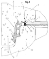
- the at least one load transfer element 1 shown in FIGS. 4 and 5 differs from that of the first embodiment. It has on its inner surface 13 opposite side two transversely spaced and projecting support lips 27, 28 which are spaced from each other at vertical load of the manhole section 3 and support this via the at least one load transfer element 1 at the spigot end 22 of the next lower manhole part 3demweg Friction on the annular surface 6 of the spigot end 22.
- the support lips 27, 28 are hinged so that an enlarged support surface 4 and bearing surface for support on the annular surface 6 at the spigot end 22 is formed. It can be seen that the support lips 27, 28 are widely spread apart, such that they with their in the undeformed state (Fig. 5) each other facing sides practically at the same height as the central region of the support surface. 4
- This at least one load-transfer element 1 has on the side opposite the inner surface 13 an approximately U-shaped cross section, as shown in FIG. 5. Instead, an inverted approximately V-shaped cross section is possible.
- the support lips 27, 28 have on the mutually facing sides projections 29, in particular toothings, which counteract due to increased friction of a provision of spread support lips 27, 28 (FIG.
- the at least one load transfer element 1 further comprises at least one anchoring part 8, which is arranged approximately centrally as in the first embodiment, in this case centrally with respect to the two support lips 27, 28th
- the at least one load transfer element 1 according to the second embodiment is thus formed at least on its inner surface 13 opposite side thus as Saugnapfartig acting suction holder. It may be formed of an elastomer.
- the part of the at least one load transfer element 1 which has or joins the at least one anchoring part 8 and / or the inner face 13, that is to say the part offset by dashed lines consists of a material of greater hardness than the material from which the support lips 27, 28 are provided.
- the support lips 27, 28 are elastic. Both material components of the one-piece load-transfer element 1 can be connected and manufactured by coextruding two different materials in an injection process to form an inseparable unit.
- This load-transfer element 1 has the advantage that its cross-section, when compressed with the two support lips 27, 28, slides along the annular surface 6 and can not or hardly spring back due to the fact that high friction occurs.
- the additional projections 29, in particular the toothing, makes such a provision more difficult.
- Another advantage is that the spread-apart support lips 27, 28 lead to a very good sealing effect, since at internal or external pressure in each case the corresponding support lip 27, 28 is pressed against the annular surface 6 of the spigot end 22.
- this load-transfer element 1 behaves like a suction cup in the form of the suction holder and thus creates a vacuum in the region of the support surface 4 during the possible spring-back, which can likewise prevent spring-back.
- the cross-section of the load transfer element 1 is designed such that the upper inner surface 13, where the at least one anchoring part 8 is provided, lies flat against the inner annular surface 2 and the anchoring part 8 is centered with respect to the support lips 27, 28.
- the load transfer element 1 can spread on both sides during compression, without here on the material, in particular the concrete, a strong lateral pressure. It is not shown that even in the area of the inner surface 13 and / or the sealing strips 16 running at the same height, projections corresponding to the projections 29, eg toothings, can be provided, which favor the spreading but complicate the contraction.
- the support lips 27, 28 may have a height in the order of about 4 mm to 6 mm in the unloaded state (FIG. 5). This corresponds approximately to the maximum height of any unevenness of the annular surface 6 of the spigot end 22, so that it is ensured that during compression the support lips 27, 28 still rest in the entire area and a corresponding sealing effect is achieved.
- the support device 11 can optionally have, in addition to the at least one load transfer element 1, at least one compression seal, e.g. similar to the first embodiment in FIGS. 1 and 2, wherein this compression seal may be an independent, with respect to the load transfer element 1 separate component. Instead, however, the compression seal may also form, together with the load transfer element 1, a one-piece sealing element.
- the receptacle 21, in particular groove, of the lower sleeve 20 in adaptation to the e.g. rectangular cross section of the at least one load transfer element 1 designed approximately U-shaped.
- the receptacle 21, e.g. Groove, the lower sleeve 20 in adaptation to the shape of the undeformed load transfer element 1 with the downwardly projecting support lips 27, 28 approximately W-shaped and formed such that the bottom of the U, for. is increased approximately hemispherical upwards.
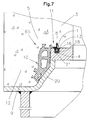
- the support means 11 in addition to the at least one load transfer element 1, at least one compression seal 10 which is held at the bell socket end 5 by casting in at least one anchoring part 54 in the manufacture of the manhole finished part 3, if necessary and desired, or the instead, it is tensioned onto the spigot end 22 of the lower manhole section 3.
- the at least one compression seal 10 is made of an elastomer and is elastically deformable. For this purpose too, it is advantageous if the compression seal 10 is elastic, but the at least one load transfer element 1 is plastically deformable.
- the at least one load transfer element 1 and the at least one compression seal 10 form an integral sealing element 65.
- an elastomer advantageously has e.g. Ring shape. It may be formed of an extruded profile, the ends od.dergl in the manner described by gluing, welding. are connected to a ring. It may instead also be formed from an injection molded part.
- this one-piece sealing element 65 its at least one load transfer element 1 has a greater hardness than its at least one compression seal 10. Both components of the sealing element 65 are inseparably connected to form a unit, which is in particular e.g. can be done by coextruding two different materials of different hardness in an injection process.
- the one-piece sealing element 65 is held on the bell socket end 5 in that at least one anchoring part is concreted in with the production of the manhole part, for example, the at least one anchoring part 8 and / or the at least one anchoring part 54 of the compression seal 10. As required, the sealing element 65 instead but also with tension on the spikes 22 have been raised.
- the design as a one-piece sealing element 65 allows a very cost-effective production, since only a single profile must be made.
- This can be constructed in terms of properties so that the compression seal 3 ensures a perfect sealing effect when stacking the manhole panels 3 by pressing in the elastic region and the load transfer element 1 ensures a uniform load transfer between the manhole components 3 by deformation in the plastic region, such that at any point Concrete contact or point loads occur.
- the at least one load transfer element 1 is not resilient, wherein its strength and hardness are chosen so that at best only to a small extent elastic deformation occurs and thus also a spring back after relief takes place only to a negligible extent. Due to the one-piece design of the sealing element 65, in the manufacture of the precast concrete part 3, the load transfer element 1 in the receptacle 21, e.g. Groove, the lower sleeve 20 are pressed, wherein the compression seal 10 is externally mounted on the lower sleeve 20. As a result, the one-piece sealing element 65 is held vibration-proof.
- Shaft finished parts 3 and structures formed thereby 7 need not be round. They can also be rectangular or square. Also in this case, the one-piece sealing element 65 is biased onto the associated lower sleeve 20, wherein the sealing element 65 is held very well over the entire circumference. In rectangular lower sleeves thus the one-piece sealing element 65 is held in an advantageous manner shaking and sealing on the lower sleeve 20.
- the sealing element 65 made of an elastomer can the required properties according to DIN 4060 and DIN EN 681-1 be taken into account.
- the load transfer element 1 is dimensioned in its cross-section and its bearing surface so that under pressure load, the yield point is exceeded and a permanent deformation of the load transfer element 1 occurs, that is, this cross section is very small, so that when superimposing the manure elements 3 on the site at bottlenecks between the annular surfaces 2 and 6 existing joint, the yield point of the elastomer is exceeded and thus no significant voltage spikes can occur. Because the compression seal 10 is elastically deformable in the sealing element 65 and the load transfer element 1 is plastically deformable, a perfect sealing effect is achieved due to the compression seal 10 between the manhole sections 3. The harder load transfer element 1 deforms plastically when the yield point is exceeded, so that the most uniform transfer of load between the manhole components 3 is achieved.
- the one-piece sealing element 65 can be produced as a profile and designed as a ring part by connecting the ends. As a result, the production costs are significantly reduced. With the different material properties, the sealing element 65 can be adapted very precisely to the respective requirements of the shaft construction. Since the one-piece sealing element 65 is completely concreted in by means of the anchoring parts 8, 54 and thereby held at the manhole element 3, no loose parts fall during the assembly of manhole structures 7 at the construction site, so that sources of error are largely eliminated. The design of the one-piece sealing element 65 made of an extruded profile can be produced efficiently and cost-effectively, even with different material properties in accordance with the requirements for the compression seal 10 and the load-transfer element 1.
- the one-piece sealing element 65 can also be mounted with tension on a spigot end 22.
- the sealing element 65 is not anchored by setting in concrete during production, but it is only at the Assembly of the shaft structure 7 mounted in the excavation on the spigot end 22 and thereafter the next manhole section 3 is placed.
- the sealing element 65 is thus a loose component.
- the advantage here is the reduced effort, since an installation during the manufacture of the manhole prefabricated parts 3 is not required.
- the one-piece sealing element 65 in the manufacture of the manhole element 3 by casting or shaking on a lower sleeve 20 are held.
- the sealing element 65 is about 3 - 5% smaller in size than the lower sleeve 20 and is mounted with bias on the lower sleeve. Slippage or lifting of the sealing element 65 during the shaking operation is additionally avoided by the load transfer element 1 in the receptacle 21, e.g. Groove, is held.
- the prestressing for pressing the sealing element 65 against the lower sleeve is not present on the straight sides, so that in this case the one-piece sealing element 65 is held in a particularly advantageous manner with the load transmission element 1 in the groove.
- the one-piece sealing element 65 can be manufactured in an extremely rational manner by co-extruding in a single process.
- the properties of the compression seal 10 and the load transfer element 1 during extrusion are a continuous process for producing the sealing element 65.
- This profile is produced efficiently and wound up on rolls. For production as a ring this profile is cut to the required length and od.dergl at the ends, for example by gluing, vulcanizing. connected to a closed ring, which is either cast in the manhole section 3 in the bell socket end 5 or is mounted on the spigot 22 during assembly.
- Both components of the one-piece sealing element 65 are inseparably combined to form a unit during production by co-extruding two different materials in an injection molding process.
- the extrusion die 65 two different materials are supplied to produce the sealing element, which are inseparably connected to a unit during coextrusion.
- the different materials are selected so that an elastic material is used for the compression seal 10 and a plastic material of greater hardness is used for the load transfer element 1.
- Both materials merge into one unit during extrusion, so that the one-piece sealing element 65 can be produced in an advantageous and rational manner and the properties are precisely matched to the requirements of the shaft construction.
- the thus very rationally producible sealing element 65 thus has optimal properties, so that all the requirements of the shaft construction are met in an extremely favorable manner. On the one hand, a perfect sealing effect is achieved and, on the other hand, the stability and longevity of the shaft structures 7 are ensured.
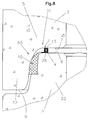
- the one-piece sealing element 65 is designed differently from the third embodiment. Deviating from this, it is mounted on the spigot end 22 as a loose part with prestressing. In this case, the load transfer element 1 sets on the annular surface 6 of the spigot 22. By placing the next manhole section 3, the compression seal 10 is compressed in gap between the spigot end 22 and the bell socket end 5, whereby the desired sealing effect arises. The upper shaft precast part 3 rests with the inner annular surface 2 on the load transfer element 1.
- the support device 11 in Fig. 9 in comparable to that in Fig. 8, but wherein the load transfer element 1 is modified.
- the inner surface 13 and the opposite side, where the support surface 4 is located each deepened from the outside in that vertical loading of the shaft precast part 3 and support this via the at least one load transfer element 1 at the spigot end 22 of the lower manhole part 3 under a change in shape of the load transfer element 1, a flattening of the inner surface 13 and / or outer surface 4 with enlargement of the support surface and support surface is formed.
- the material of the load transfer element 1 slides in the region of the inner surface 13 and / or the support surface 4 along the concrete, which due to the resulting increased friction only a poor spring back is possible.
- protruding projections e.g. Gears
- the load transfer element 1 behaves Saugnapfartig and thus the possible spring back creates a vacuum, which can also prevent springing back.
- the invention is, as can be seen from the above description, not only a manhole finished part, for example in the form of a cone or a manhole ring or, as far as the spigot end 22, a lower part, or any lid, which can be placed on a spigot of a manhole ring is
- a manhole finished part for example in the form of a cone or a manhole ring or, as far as the spigot end 22, a lower part, or any lid, which can be placed on a spigot of a manhole ring is
- This sub-sleeve 20 which is rectangular or square, depending on the design, for example, circular or rectangular or square for the production of rectangular or square prefabricated parts 3, has an upwardly open receptacle 21, for example groove, into which the at least one load-transfer element 1 is pressed.
- the compression seal 10 On the lower sleeve 20, the compression seal 10, if any, is mounted on the outside.
- the load transfer element 1 is shakeproof and well held by appropriate positive engagement and through the clamping bars 18 increased voltage, which is held in the design as a one-piece sealing element 65 and the compression seal 10, which anyway by the mounting on the lower sleeve 20th - Even in the two-part design according to the first embodiments - is securely held on the lower sleeve 20.
- the compression seal 10 and / or the at least one load transfer element 1 is not embedded by means of the anchoring parts 54 and 8 in the manufacture of the manhole element 3, but instead is mounted as a loose part on the spigot end 22 of the manhole element 3 , for example, according to Fig. 8 and 9, eliminates the prior attachment to the lower sleeve 20, since this mounting on the spigot 22 is done only after completion.
- the shape of the receptacle 21, in particular groove, the lower sleeve 20 is adapted to the contour of the at least one load-transfer element and, for example. U-shaped or in the case of the load transfer element 1 according to FIGS. 4 and 5 approximately W-shaped.
- the invention is in addition to the manhole module and method for its production, a support device 11 for such manhole components 3, said support means 11 having the features described in detail hereinabove and shown in the drawings, which relate to the at least one load transfer element 1 in all variations and / or the compression seal 10, both in the two-part embodiment and in FIG the one-piece design as a sealing device in the form of the sealing element 65. Alone to avoid unnecessary repetition is here omitted to repeat this only the support device 11 concerned features of the individual components here.
Landscapes
- Engineering & Computer Science (AREA)
- General Engineering & Computer Science (AREA)
- Mechanical Engineering (AREA)
- Life Sciences & Earth Sciences (AREA)
- Structural Engineering (AREA)
- Paleontology (AREA)
- Civil Engineering (AREA)
- Mining & Mineral Resources (AREA)
- General Life Sciences & Earth Sciences (AREA)
- Environmental & Geological Engineering (AREA)
- Hydrology & Water Resources (AREA)
- Health & Medical Sciences (AREA)
- Public Health (AREA)
- Water Supply & Treatment (AREA)
- Manufacturing & Machinery (AREA)
- Chemical & Material Sciences (AREA)
- Ceramic Engineering (AREA)
- Underground Structures, Protecting, Testing And Restoring Foundations (AREA)
Applications Claiming Priority (2)
| Application Number | Priority Date | Filing Date | Title |
|---|---|---|---|
| DE200410041301 DE102004041301A1 (de) | 2004-08-25 | 2004-08-25 | Schachtfertigteil aus Beton |
| DE102004059269 | 2004-12-08 |
Publications (2)
| Publication Number | Publication Date |
|---|---|
| EP1630308A2 true EP1630308A2 (fr) | 2006-03-01 |
| EP1630308A3 EP1630308A3 (fr) | 2008-09-10 |
Family
ID=35414563
Family Applications (1)
| Application Number | Title | Priority Date | Filing Date |
|---|---|---|---|
| EP20050012406 Withdrawn EP1630308A3 (fr) | 2004-08-25 | 2005-06-09 | Elément de regard préfabriqué en béton |
Country Status (1)
| Country | Link |
|---|---|
| EP (1) | EP1630308A3 (fr) |
Cited By (2)
| Publication number | Priority date | Publication date | Assignee | Title |
|---|---|---|---|---|
| DE102007028324B4 (de) | 2007-06-06 | 2021-08-05 | Hans Rinninger U. Sohn Gmbh U. Co. | Schacht aus Beton und Lastaufnahmeelement |
| CN114908706A (zh) * | 2022-04-19 | 2022-08-16 | 南水北调中线干线工程建设管理局河南分局 | 水下装配式预制导流墩 |
Citations (6)
| Publication number | Priority date | Publication date | Assignee | Title |
|---|---|---|---|---|
| DE3818064A1 (de) | 1988-05-27 | 1989-12-07 | Gerhard Preisendoerfer | Abdichtung an zusammensteckbaren betonfertigteilen |
| EP0543103A1 (fr) | 1991-11-21 | 1993-05-26 | Forsheda AB | Dispositif d'étanchéité |
| EP0634532B1 (fr) | 1993-07-15 | 1999-03-10 | Georg Prinzing GmbH & Co. KG Betonformen- und Maschinenfabrik | Arrangement pour joint d'étanchéité pour élément de construction |
| EP1104825A2 (fr) | 1999-11-11 | 2001-06-06 | Merbeler AG | Elément de regard, en particulier anneau de regard en béton |
| DE10140928A1 (de) | 2001-05-31 | 2002-12-05 | Prinzing Georg Gmbh Co Kg | Betomformteil, insbesondere Schachtring |
| DE10148574C1 (de) | 2001-10-01 | 2003-02-13 | Wagener & Polascheck Vertriebs | Verfahren zum Herstellen von Schachtringen und Vorrichtung zu dessen Durchführung |
-
2005
- 2005-06-09 EP EP20050012406 patent/EP1630308A3/fr not_active Withdrawn
Patent Citations (6)
| Publication number | Priority date | Publication date | Assignee | Title |
|---|---|---|---|---|
| DE3818064A1 (de) | 1988-05-27 | 1989-12-07 | Gerhard Preisendoerfer | Abdichtung an zusammensteckbaren betonfertigteilen |
| EP0543103A1 (fr) | 1991-11-21 | 1993-05-26 | Forsheda AB | Dispositif d'étanchéité |
| EP0634532B1 (fr) | 1993-07-15 | 1999-03-10 | Georg Prinzing GmbH & Co. KG Betonformen- und Maschinenfabrik | Arrangement pour joint d'étanchéité pour élément de construction |
| EP1104825A2 (fr) | 1999-11-11 | 2001-06-06 | Merbeler AG | Elément de regard, en particulier anneau de regard en béton |
| DE10140928A1 (de) | 2001-05-31 | 2002-12-05 | Prinzing Georg Gmbh Co Kg | Betomformteil, insbesondere Schachtring |
| DE10148574C1 (de) | 2001-10-01 | 2003-02-13 | Wagener & Polascheck Vertriebs | Verfahren zum Herstellen von Schachtringen und Vorrichtung zu dessen Durchführung |
Cited By (3)
| Publication number | Priority date | Publication date | Assignee | Title |
|---|---|---|---|---|
| DE102007028324B4 (de) | 2007-06-06 | 2021-08-05 | Hans Rinninger U. Sohn Gmbh U. Co. | Schacht aus Beton und Lastaufnahmeelement |
| CN114908706A (zh) * | 2022-04-19 | 2022-08-16 | 南水北调中线干线工程建设管理局河南分局 | 水下装配式预制导流墩 |
| CN114908706B (zh) * | 2022-04-19 | 2023-12-19 | 南水北调中线干线工程建设管理局河南分局 | 水下装配式预制导流墩 |
Also Published As
| Publication number | Publication date |
|---|---|
| EP1630308A3 (fr) | 2008-09-10 |
Similar Documents
| Publication | Publication Date | Title |
|---|---|---|
| EP1929109B1 (fr) | Concept de tour | |
| DE202009014434U1 (de) | Unterlegplatte für die Befestigung einer Schiene auf einem festen Untergrund und Befestigung einer Schiene | |
| DE102016115042A1 (de) | Turm für eine Windkraftanlage aus ringsegmentförmigen Betonfertigteilen | |
| DE202009014430U1 (de) | Unterlegplatte für die Befestigung einer Schiene auf einem festen Untergrund und Befestigung einer Schiene | |
| DE2910090A1 (de) | Dichtungsstreifen zum abdichten von stossfugen und kreuzungsstellen zwischen bauelementen | |
| DE202009014462U1 (de) | System zum Befestigen einer Schiene auf einem festen Untergrund und Befestigung einer Schiene | |
| EP0308876B1 (fr) | Dispositif de support élastique pour rails à gorge | |
| EP2925932B1 (fr) | Dispositif de pontage pour joints de dilatation | |
| EP0077918B1 (fr) | Jointe d'étanchéité pour jonction à emmanchement de tuyaux en béton | |
| EP1040238B1 (fr) | Armature de cisaillement pour plafonds plats et profile a goujons correspondant | |
| EP0634532A2 (fr) | Arrangement pour joint d'étanchéité pour élément de construction | |
| CH665464A5 (de) | Steckmuffendichtung an einem betonrohr. | |
| DE8909099U1 (de) | Anschlußschalung für aneinander anschließende Betonplatten | |
| DE8916127U1 (de) | Vorrichtung zur federnden Einspannung von Traversen einer Fahrbahnüberbrückungskonstruktion | |
| EP1630308A2 (fr) | Elément de regard préfabriqué en béton | |
| DE19949839C1 (de) | Montageträgersystem mit Einbauhilfe | |
| DE19954492C1 (de) | Schachtbauteil, insbesondere Schachtring aus Beton | |
| DE3744017C2 (de) | Stahlbeton-Raumzelle, insbesondere Fertiggarage | |
| WO2012126025A1 (fr) | Dispositif pour réaliser un joint de dilatation | |
| DE3302075A1 (de) | Spannbeton- oder stahlbetonbiegetraeger | |
| WO1996000855A1 (fr) | Assemblage de profiles en acier | |
| EP3865623A1 (fr) | Profil d'assemblage | |
| DE102011105334B4 (de) | Schacht aus Beton und Lastaufnahmeelement | |
| WO2018114898A1 (fr) | Système de canalisation et procédé de montage de celui-ci | |
| DE102004041301A1 (de) | Schachtfertigteil aus Beton |
Legal Events
| Date | Code | Title | Description |
|---|---|---|---|
| PUAI | Public reference made under article 153(3) epc to a published international application that has entered the european phase |
Free format text: ORIGINAL CODE: 0009012 |
|
| AK | Designated contracting states |
Kind code of ref document: A2 Designated state(s): AT BE BG CH CY CZ DE DK EE ES FI FR GB GR HU IE IS IT LI LT LU MC NL PL PT RO SE SI SK TR |
|
| AX | Request for extension of the european patent |
Extension state: AL BA HR LV MK YU |
|
| PUAL | Search report despatched |
Free format text: ORIGINAL CODE: 0009013 |
|
| AK | Designated contracting states |
Kind code of ref document: A3 Designated state(s): AT BE BG CH CY CZ DE DK EE ES FI FR GB GR HU IE IS IT LI LT LU MC NL PL PT RO SE SI SK TR |
|
| AX | Request for extension of the european patent |
Extension state: AL BA HR LV MK YU |
|
| 17P | Request for examination filed |
Effective date: 20081004 |
|
| 17Q | First examination report despatched |
Effective date: 20090126 |
|
| AKX | Designation fees paid |
Designated state(s): AT BE BG CH CY CZ DE DK EE ES FI FR GB GR HU IE IS IT LI LT LU MC NL PL PT RO SE SI SK TR |
|
| STAA | Information on the status of an ep patent application or granted ep patent |
Free format text: STATUS: THE APPLICATION IS DEEMED TO BE WITHDRAWN |
|
| 18D | Application deemed to be withdrawn |
Effective date: 20150807 |