EP1630320A2 - Modulare Handlaufsysteme - Google Patents
Modulare Handlaufsysteme Download PDFInfo
- Publication number
- EP1630320A2 EP1630320A2 EP05076946A EP05076946A EP1630320A2 EP 1630320 A2 EP1630320 A2 EP 1630320A2 EP 05076946 A EP05076946 A EP 05076946A EP 05076946 A EP05076946 A EP 05076946A EP 1630320 A2 EP1630320 A2 EP 1630320A2
- Authority
- EP
- European Patent Office
- Prior art keywords
- connectors
- kit
- male
- connector
- parts
- Prior art date
- Legal status (The legal status is an assumption and is not a legal conclusion. Google has not performed a legal analysis and makes no representation as to the accuracy of the status listed.)
- Granted
Links
- 238000010276 construction Methods 0.000 claims abstract description 4
- 239000000463 material Substances 0.000 claims description 6
- 239000004033 plastic Substances 0.000 claims description 4
- 229920003023 plastic Polymers 0.000 claims description 4
- 238000001125 extrusion Methods 0.000 claims description 3
- 238000000465 moulding Methods 0.000 claims description 2
- 230000001154 acute effect Effects 0.000 description 4
- 239000000470 constituent Substances 0.000 description 2
- 230000001419 dependent effect Effects 0.000 description 2
- 239000000853 adhesive Substances 0.000 description 1
- 230000001070 adhesive effect Effects 0.000 description 1
- 230000001174 ascending effect Effects 0.000 description 1
- 230000000712 assembly Effects 0.000 description 1
- 238000000429 assembly Methods 0.000 description 1
- 230000015556 catabolic process Effects 0.000 description 1
- 238000006731 degradation reaction Methods 0.000 description 1
- 230000002708 enhancing effect Effects 0.000 description 1
- 230000001771 impaired effect Effects 0.000 description 1
- 239000002184 metal Substances 0.000 description 1
- 238000000034 method Methods 0.000 description 1
- 239000012763 reinforcing filler Substances 0.000 description 1
- 238000010079 rubber tapping Methods 0.000 description 1
Images


Classifications
-
- E—FIXED CONSTRUCTIONS
- E04—BUILDING
- E04F—FINISHING WORK ON BUILDINGS, e.g. STAIRS, FLOORS
- E04F11/00—Stairways, ramps, or like structures; Balustrades; Handrails
- E04F11/18—Balustrades; Handrails
- E04F11/181—Balustrades
Definitions
- the present invention relates to modular handrail systems and in particular to a kit of parts for assembly into such handrails, as well as a modular handrail system constructed therefrom.
- handrails must be provided in a variety of temporary and permanent locations.
- One example is when providing ramps or steps for gaining access into buildings or otherwise. Such ramps and steps must now be provided with some form of handrail system to aid people using the ramps or steps and to improve their safety.
- the present invention aims to improve upon these and to provide a modular handrail system that may be easily constructed into a variety of different configurations to suit the particular circumstances of its use. It is a further aim to provide a handrail system that is light and strong as well as being resistant to atmospheric degradation and cost efficient to produce. It is a further aim to provide a handrail that may be easily and swiftly assembled and disassembled in situations where only a temporary construction is required.
- handrail As used herein the terms “handrail”, “railings” or “handrail system” are used to describe a fence-like or barrier-like structure, usually but not exclusively vertically arranged, and having one or more leg and one or more rail running approximately perpendicular to the legs - and usually parallel to the surface. The purpose of such items is to provide a means of support to those holding it and to prevent accidental falls or improper passage of persons.
- kits of parts for construction of a handrail assembly including at least one cross connector having male projections in an opposed pair; at least one T-shaped connector having at least one male projection; a plurality of elongate tubular sections each adapted to connect to the male projections of different connectors thereby to form an assembly of intersecting legs and rails; and at least one base member that is adapted to connect to the end of a tubular section and to an external structure to mount the handrail assembly thereon, each male projection having an annular rib that engages in a groove formed in the inner surface of each tubular section.
- the kit is also provided with one or more curved connector having two male projections formed at an angle, less then 180°, relative to each other.
- a curved projector will often have the male projections formed at substantially 90° relative to each other such that the connector may connect a horizontal and a vertical tubular section to form a smooth corner.
- the diameter of that curve may vary dependent upon the particular application. For example a large diameter curve may be appropriate when terminating a rail at a free end by joining it to a rail below, but a small diameter curve is usually better when turning a horizontal corner on a rail.
- variable angle connector having two parts each provided with a male projection and each being moveable relative to the other.
- a variable connector would preferably comprise two parts pivotally connected to each other such that a desired relative angle of the male projections and hence any tubular sections to which they are connected can be achieved, by pivoting about a common axis of rotation.
- the cross-connector and the T-shape connectors may comprise two opposed pairs of male projections and these may be generally regular In orientation with the connectors at right angles to each other such that the tubular sections connected thereto are also substantially at right angles.
- This is particularly appropriate where a railing is to extend along a flat surface and each rail is to run essentially parallel to that surface and perpendicular to each leg.
- each rail is to run essentially parallel to that surface and perpendicular to each leg.
- the legs remain essentially vertical (rather than perpendicular to the general incline of the surface) but the rails should remain essentially parallel to that surface incline.
- one opposed pair of male projections is at an acute angle to the other pair of opposed male projections, the male projections being all in the same plane.
- this may comprise three male projections, and tubular sections may attach to each of these projections.
- the T-shaped connector often forms the upper end of a leg and connects to an uppermost rail. It may provide suitable angles and it is preferred that there is a pair of diametrically opposed male projections that connect to the tubular sections forming an upper rail and that the other male projection is formed at an acute angle relative to one of those male projections. Again all male projections are in substantially the same plane.
- a kit may include both angles and regular T-connectors and cross connectors.
- the kit of parts may include one or more half connector that defines a single male projection and is connectable to a middle portion of a tubular section.
- a half connector can be used in addition to the cross connectors and T-shaped connectors, but can also be used to form such connectors.
- the cross connector may comprises two half connectors that each define a male projection, the two half connectors being attachable to opposite sides of a tubular section.
- a T-shaped connector may comprise a single half connector attached to the middle of one tubular section and the end of another.
- Each half connector may preferably have a channel shaped base portion that locates around the external surface of the tubular section, and a male projection extending in the opposite direction therefrom.
- the channel shaped base portion will have a profile that matches the shape of the tubular section, and the male projection may be formed at a range of angles to the axis of the tubular section to which the half connector is attached.
- each component is constructed wholly or predominantly from a plastics material, due in part to their high strength to weight ratios.
- the plastics material may also include reinforcing filler materials such as fibres.
- the connectors are formed by moulding and the tubular sections, which are usually elongate and rectilinear, are formed by extrusion.
- tubular sections are generally circular in cross-section and define a generally circular hollow interior. It is preferred that the male projections are also generally circular in cross-section and are adapted to be a tight fit within the hollow interior of the tubular section.
- the hollow interior of the tubular section has at least one groove formed therein to receive the rib on each male projection, which serves not only to ensure correct angular orientation but also prevents any rotation of the tubular section relative to the male projection.
- each connector with the possible exception of the variable angle connector and half connector, has a main body and male projections extending therefrom. It is preferred that the main body is approximately equivalent in dimensions and profile to the tubular sections. This helps to ensure that there is a regular, smooth and continuous external profile regardless of whether it is a tubular section or a part of a connector.
- the male projections extend from the main body of each connector and are slightly smaller in diameter such that they are a snug fit within the hollow tubular sections.
- the tubular sections are usually intended to be gripped by the hand and consequently they may be provided with grip enhancing features such as ridges.
- the connectors are distinguishable by touch from the tubular sections so that someone of impaired sight can distinguish by touch alone when their hand passes over a connector, thus giving a guide to the distance travelled.
- a handrail when constructed from a kit of parts as previously defined.
- a modular handrail system having a plurality of legs and at least one rail, the system comprising T-connectors having at least one male projection and located at the upper end of each leg, a plurality of cross connectors having at least two male projections in an opposed pair, elongate tubular sections, the open ends of which connect around the male projections of the T-connectors and cross connectors to interconnect them to form the legs and at least one rail, and a base member adapted to connect to a free end of a tubular section either of a leg or a rail and to an external structure to connect the leg or rail thereto, each male projection having an annular rib that engages in a groove formed in the inner surface of each tubular section.
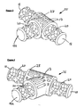
- FIG. 1 shows a large diameter 90° curved connector generally indicated 15.
- This curved connector 15 will usually be used as an end bend and is of a relatively large diameter of curvature.
- the curved connector 15 comprises a main body 16 which is generally curved and circular in cross-section, with a diameter equivalent to the tubular section described below.
- a series of depressions 17 are formed in the main body 16 and male projections 18 extend from the two ends,
- the male projections 18 are generally circular in profile and each has a radially extending rib 19 provided thereon that runs parallel to the axis of the projection.
- One or more recess 20 is provided on each male projection 18 to receive a fixing screw (not shown).
- the male projections 18 are inserted into the hollow interior of the tubular sections and the fixing screws if needed pass through the wall of the tubular section to engage in the recess 20.
- the recesses may be provided with a thread or may be adapted to receive a self-tapping screw.
- the smaller diameter curved connector shown in Figure 2 is generally indicated 22 and, apart from the length of the main body 16 and the radius or curvature, is essentially identical to that described in Figure 1 and like parts have been given like reference numerals.
- FIG 3 shows a 90° T-connector generally indicated 25 and Figure 4 shows an alternatively angled T-connector generally indicated 26.
- These T-connectors are usually intended to form the upper end of a leg (which itself comprises one or more tubular section and other connectors).
- Each T-connector 25, 26 has three male projections 18, two of which are formed at 180° to each other in an opposed pair, which pair connects to tubular sections to form the upper rail of a handrail assembly.
- the third or middle connector, labelled 18A is intended to connect to the upper end of an upper tubular section of a leg of the rail assembly.
- the middle male projection 18A is formed at 90° to the other male projections.
- each connector still comprises a main body which is essentially similar to that of the curved connectors but is herein labelled 27 and 28 due to their alternative configurations.
- each male projection 18 and 18A have a rib 19 formed thereon as well as screw recesses 20.
- T-connectors could also be used to terminate a rail section in a leg, such that the opposed pair connect to tubular sections forming part of the leg and the middle male projection 18A connects to a tubular section forming part of the rail.
- Figures 5 and 6 show regular and angled embodiments of cross-connectors.
- each male projection 18 is formed at substantially right angles to each other in opposed pairs, all male projections being in the same plane.
- This cross connector 30 would be used to connect four tubular sections together and generally one opposed pair would connect together tubular sections forming part of a leg and the other opposed pair would connect tubular sections forming part of an intermediate (i.e. not upper) rail.
- each male projection would be provided with the rib 19 and the screw recesses 20, even though not all parts are visible in Figures 5 and 6.
- Figure 6 is essentially equivalent to that shown in Figure 5, but this angled cross-connector generally indicated 31 has one pair of opposed male projections 18 formed at an acute angle to the other pair.
- This arrangement allows a leg and a rail of the assembly to be formed at an angle relative to each other, other than 90°, such that a leg may remain essentially vertical whilst the rail that it supports may run parallel to the surface adjacent which the railing assembly is constructed.
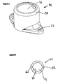
- Figure 7 shows a base member in the form of a connector plate generally indicated 35.
- This connector plate 35 is adapted to receive the end of a tubular section within an aperture 36 formed by an upstanding sleeve 38 and the connector plate 35 may then be connected by screws or other suitable fixings passing through apertures 37 to an external structure such a floor.
- a connector plate 35 can be used to connect the lower end of a leg to a floor or ramp, but also can be used to connect the end of a rail to a vertical surface such as a wall. It is also possible for the connector plate 35 to be provided with a male projection equivalent to those described above such that the joined tubular section connects around the male projection rather than locating into the recess 36.
- FIG. 8 A cross-section through a tubular section 40 generally indicated is shown in Figure 8.
- the external surface is provided with raised and lowered regions in order to improve the grip.
- the tubular section 40 has an equivalent cross-section along its entire length, and formed by extrusion of like technique. It can be formed in long sections that may be cut to an appropriate length to suit particular requirements.
- the tubular section 40 is generally circular and has a hollow interior 41. Channels 42 are formed on the inner surface 43 of the tube and the ribs 19 provided on the male projections 18 are adapted to locate within one of these channels 42 to prevent rotation of the tubular section 40 about the male projection 18.
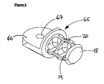
- Figure 9 shows one half of a variable angled connector.
- the half which is generally indicated 45, has a male projection 18 and associated components such as the rib 19 and is adapted to connect at a variety of pivotal angles to a second like half (not shown).
- the main body of the half 45 has a flat plate 46 and a pivot bore 47.
- the equivalent parts of a second half are aligned such that the pivot bores 47 coincide and the two halves can be connected together by a pivot pin (not shown), or by a male part on one half locating into the pivot bore of the other. This provides a connector that can be used to alter the angle at which a rail or leg extends.
- FIGS 10 and 11 show respectively an exploded and a constructed view of part of a rail assembly constructed from some of the components previously discussed.
- a series of intersecting legs and rails are constructed.
- Each leg is formed from a T-connector 25, a cross-connector 30, a connector plate 35 and two tubular sections 40.
- Generally horizontal rails are then formed by inter-connecting the laterally extending male projections 18 on the T-connectors 25 and the cross-connectors 30 with further tubular sections 40.
- a curved free end of the rail assembly is formed using two curved connectors 15 and a shortened tubular section 40 in a U-shaped configuration to connect the ends of the substantially parallel rails.
- a variable angle connector generally Indicated 60 formed from two constituent halves 45 and is used to alter the angle of the rails.
- the lower ends of the lowermost tubular sections 40 are located into the aperture 36 of the connector plates 35 which, as best shown in Figure 11, are connected to a surface 61 upon which the rail assembly overall is mounted.
- the angled T-connectors 26, angled cross-connectors 27 and the smaller diameter curved connectors 22 could all be used to make different or more complicated handrail assemblies dependent upon the requirement.
- the connector plates 35 can be attached to a wall at a termination of a generally horizontal rail as well as supporting the lower end of a leg section 50.
- FIGS 12 and 13 show a half connector generally indicated 70.
- This half connector comprises a curved base region 71 and a male projection 18 extending therefrom for connection to a tubular section as described above.
- the curved base region locates around the curved surface of a tubular section and is connected thereto using suitable means such as bolts, screws or adhesive.
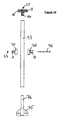
- Figure 14 shows a leg of a possible assembly using two half connectors 70 to form a cross connector.
- a length 73 of tubular section connects to the male projection 74 of a base member 75 to fix the leg down to an external structure.
- a T-connector 25 connects to the upper end of the length 73 for forming a top rail.
- a bolt 76 passes through each half connector and a transverse hole in the length 73, and a nut 77 is threaded thereon.
- Tubular sections may be attached to the male projections 18 of the half connectors 70 to form a lower rail (not shown).
Landscapes
- Engineering & Computer Science (AREA)
- Architecture (AREA)
- Civil Engineering (AREA)
- Structural Engineering (AREA)
- Mutual Connection Of Rods And Tubes (AREA)
- Steps, Ramps, And Handrails (AREA)
- Bridges Or Land Bridges (AREA)
Applications Claiming Priority (1)
| Application Number | Priority Date | Filing Date | Title |
|---|---|---|---|
| GBGB0418862.9A GB0418862D0 (en) | 2004-08-24 | 2004-08-24 | Railings |
Publications (3)
| Publication Number | Publication Date |
|---|---|
| EP1630320A2 true EP1630320A2 (de) | 2006-03-01 |
| EP1630320A3 EP1630320A3 (de) | 2008-04-02 |
| EP1630320B1 EP1630320B1 (de) | 2012-03-14 |
Family
ID=33104546
Family Applications (1)
| Application Number | Title | Priority Date | Filing Date |
|---|---|---|---|
| EP05076946A Expired - Lifetime EP1630320B1 (de) | 2004-08-24 | 2005-08-24 | Modulare Handlaufsysteme |
Country Status (3)
| Country | Link |
|---|---|
| EP (1) | EP1630320B1 (de) |
| AT (1) | ATE549468T1 (de) |
| GB (2) | GB0418862D0 (de) |
Cited By (4)
| Publication number | Priority date | Publication date | Assignee | Title |
|---|---|---|---|---|
| EP2003265A2 (de) | 2007-06-15 | 2008-12-17 | Burger et CIE (Société par Actions Simplifiée) | System für Geländer, Rampen oder für ähnliche Zwecke |
| WO2014100855A1 (en) * | 2012-12-24 | 2014-07-03 | Hunter Products Pty Ltd | Modular fence comprising self-closing gate |
| USD991023S1 (en) | 2017-12-21 | 2023-07-04 | Lustre Products Ltd. | Modular rail system connector |
| US11739536B2 (en) | 2017-12-19 | 2023-08-29 | Lustre Products Ltd. | Modular rail system |
Families Citing this family (2)
| Publication number | Priority date | Publication date | Assignee | Title |
|---|---|---|---|---|
| JP6293639B2 (ja) * | 2014-10-28 | 2018-03-14 | 三協立山株式会社 | 手すり |
| CN108662337B (zh) * | 2018-07-19 | 2024-02-09 | 深圳华建电力工程设计有限公司 | 一种管道组件 |
Citations (2)
| Publication number | Priority date | Publication date | Assignee | Title |
|---|---|---|---|---|
| US4706367A (en) | 1985-12-16 | 1987-11-17 | Specialty Maintenance And Construction, Inc. | System and method for mechanically joining handrailing members |
| EP1048799A1 (de) | 1999-04-30 | 2000-11-02 | M.P.S. S.R.L. | Modulare Struktur zur Herstellung von Handläufen |
Family Cites Families (10)
| Publication number | Priority date | Publication date | Assignee | Title |
|---|---|---|---|---|
| GB386436A (en) * | 1932-01-09 | 1933-01-19 | Horace Walter Dover | Improvements in or relating to hand-rails for staircases and other analogous purposes |
| DE2631259A1 (de) * | 1976-07-12 | 1978-01-26 | Greschbach Stahlbau | Steigungsveraenderliches schraub- steck-montagegelaender |
| DE3124557A1 (de) * | 1981-06-23 | 1982-12-30 | Hans Huber Gmbh & Co Kg, 8434 Berching | Gelaender aus korrosionsbestaendigem stahl |
| DE3702128C2 (de) * | 1987-01-24 | 1996-10-17 | Sks Stakusit Kunststoff Gmbh | Halterung zur ausrichtbaren Befestigung der Pfosten eines Balkongeländers |
| DE9102252U1 (de) * | 1991-02-26 | 1991-05-16 | HEWI Heinrich Wilke GmbH, 34454 Bad Arolsen | Verbindungssystem für zwei als Rohr- oder Stangen- und/oder Knotenelemente ausgebildete Bauteile |
| DE9315301U1 (de) * | 1993-10-11 | 1994-02-24 | Schott Glaswerke, 55122 Mainz | Rohrverbinder |
| GB2325943B (en) * | 1997-05-29 | 2001-10-10 | Kudos Dev Ltd | Handrail system |
| DE29803787U1 (de) * | 1998-03-05 | 1999-04-08 | Harald Böhl GmbH CNC-Dreh- und Frästechnik, 35119 Rosenthal | Rohrverbindung |
| GB2385067B (en) * | 2002-02-07 | 2006-02-15 | Burbidge Richard Ltd | Handrail assemblies |
| GB2411910A (en) * | 2004-03-09 | 2005-09-14 | Fibrerail Ltd | Modular GRP handrail |
-
2004
- 2004-08-24 GB GBGB0418862.9A patent/GB0418862D0/en not_active Ceased
-
2005
- 2005-08-24 EP EP05076946A patent/EP1630320B1/de not_active Expired - Lifetime
- 2005-08-24 GB GB0517310A patent/GB2417502A/en not_active Withdrawn
- 2005-08-24 AT AT05076946T patent/ATE549468T1/de active
Patent Citations (2)
| Publication number | Priority date | Publication date | Assignee | Title |
|---|---|---|---|---|
| US4706367A (en) | 1985-12-16 | 1987-11-17 | Specialty Maintenance And Construction, Inc. | System and method for mechanically joining handrailing members |
| EP1048799A1 (de) | 1999-04-30 | 2000-11-02 | M.P.S. S.R.L. | Modulare Struktur zur Herstellung von Handläufen |
Cited By (5)
| Publication number | Priority date | Publication date | Assignee | Title |
|---|---|---|---|---|
| EP2003265A2 (de) | 2007-06-15 | 2008-12-17 | Burger et CIE (Société par Actions Simplifiée) | System für Geländer, Rampen oder für ähnliche Zwecke |
| EP2003265A3 (de) * | 2007-06-15 | 2010-02-24 | Burger et CIE (Société par Actions Simplifiée) | System für Geländer, Rampen oder für ähnliche Zwecke |
| WO2014100855A1 (en) * | 2012-12-24 | 2014-07-03 | Hunter Products Pty Ltd | Modular fence comprising self-closing gate |
| US11739536B2 (en) | 2017-12-19 | 2023-08-29 | Lustre Products Ltd. | Modular rail system |
| USD991023S1 (en) | 2017-12-21 | 2023-07-04 | Lustre Products Ltd. | Modular rail system connector |
Also Published As
| Publication number | Publication date |
|---|---|
| EP1630320B1 (de) | 2012-03-14 |
| EP1630320A3 (de) | 2008-04-02 |
| GB0418862D0 (en) | 2004-09-29 |
| GB2417502A (en) | 2006-03-01 |
| GB0517310D0 (en) | 2005-10-05 |
| ATE549468T1 (de) | 2012-03-15 |
Similar Documents
| Publication | Publication Date | Title |
|---|---|---|
| US6752385B2 (en) | Railing system | |
| US4102529A (en) | Railing system | |
| US8505880B2 (en) | Fence rail support system | |
| US20110073824A1 (en) | Railing system and coupling element and methods of assembly | |
| US7044450B2 (en) | Quick rail system with adjustable support | |
| US20200011063A1 (en) | Tubular structure connecting assembly | |
| US5029820A (en) | Wedge-adjustable base for rail posts and the like | |
| US20080191185A1 (en) | Handrail assemblies | |
| US20070029534A1 (en) | Handrail or top rail, post and panel assembly and connector therefor | |
| KR20120116495A (ko) | 개선된 핸드레일 | |
| US9783990B2 (en) | Continuous handrail system | |
| CA2708592A1 (en) | Railing system | |
| US20060059636A1 (en) | Modular platform, walkway or ramp | |
| EP1630320A2 (de) | Modulare Handlaufsysteme | |
| US6929094B1 (en) | Restraint system, apparatus and method for ladder system | |
| EP1258577A2 (de) | Verbinderzusammenbau für die Montage eines Handlaufes | |
| US20050127346A1 (en) | Bracket system for attaching elongated members | |
| US20030006405A1 (en) | Quick rail system | |
| US20070145343A1 (en) | Articulated rail mount | |
| KR101663738B1 (ko) | 계단용 난간 | |
| US6009586A (en) | Truss and panel system for access ramps | |
| US20190119923A1 (en) | Handrail system for ramp assembly and handrail adaptor having angled interface | |
| US20190271161A1 (en) | Hidden fastener railing system | |
| EP2837751A2 (de) | Plattform zur Verwendung als Fußweg | |
| US20090184303A1 (en) | Balustrading |
Legal Events
| Date | Code | Title | Description |
|---|---|---|---|
| PUAI | Public reference made under article 153(3) epc to a published international application that has entered the european phase |
Free format text: ORIGINAL CODE: 0009012 |
|
| AK | Designated contracting states |
Kind code of ref document: A2 Designated state(s): AT BE BG CH CY CZ DE DK EE ES FI FR GB GR HU IE IS IT LI LT LU LV MC NL PL PT RO SE SI SK TR |
|
| AX | Request for extension of the european patent |
Extension state: AL BA HR MK YU |
|
| PUAL | Search report despatched |
Free format text: ORIGINAL CODE: 0009013 |
|
| AK | Designated contracting states |
Kind code of ref document: A3 Designated state(s): AT BE BG CH CY CZ DE DK EE ES FI FR GB GR HU IE IS IT LI LT LU LV MC NL PL PT RO SE SI SK TR |
|
| AX | Request for extension of the european patent |
Extension state: AL BA HR MK YU |
|
| 17P | Request for examination filed |
Effective date: 20081002 |
|
| 17Q | First examination report despatched |
Effective date: 20081030 |
|
| AKX | Designation fees paid |
Designated state(s): AT BE BG CH CY CZ DE DK EE ES FI FR GB GR HU IE IS IT LI LT LU LV MC NL PL PT RO SE SI SK TR |
|
| RAP1 | Party data changed (applicant data changed or rights of an application transferred) |
Owner name: PREFERRED ACCESS RAMP SYSTEMS LIMITED |
|
| GRAP | Despatch of communication of intention to grant a patent |
Free format text: ORIGINAL CODE: EPIDOSNIGR1 |
|
| GRAS | Grant fee paid |
Free format text: ORIGINAL CODE: EPIDOSNIGR3 |
|
| GRAA | (expected) grant |
Free format text: ORIGINAL CODE: 0009210 |
|
| AK | Designated contracting states |
Kind code of ref document: B1 Designated state(s): AT BE BG CH CY CZ DE DK EE ES FI FR GB GR HU IE IS IT LI LT LU LV MC NL PL PT RO SE SI SK TR |
|
| REG | Reference to a national code |
Ref country code: GB Ref legal event code: FG4D |
|
| REG | Reference to a national code |
Ref country code: CH Ref legal event code: EP Ref country code: AT Ref legal event code: REF Ref document number: 549468 Country of ref document: AT Kind code of ref document: T Effective date: 20120315 |
|
| REG | Reference to a national code |
Ref country code: IE Ref legal event code: FG4D |
|
| REG | Reference to a national code |
Ref country code: DE Ref legal event code: R096 Ref document number: 602005033112 Country of ref document: DE Effective date: 20120510 |
|
| REG | Reference to a national code |
Ref country code: NL Ref legal event code: VDEP Effective date: 20120314 |
|
| PG25 | Lapsed in a contracting state [announced via postgrant information from national office to epo] |
Ref country code: LT Free format text: LAPSE BECAUSE OF FAILURE TO SUBMIT A TRANSLATION OF THE DESCRIPTION OR TO PAY THE FEE WITHIN THE PRESCRIBED TIME-LIMIT Effective date: 20120314 |
|
| LTIE | Lt: invalidation of european patent or patent extension |
Effective date: 20120314 |
|
| PG25 | Lapsed in a contracting state [announced via postgrant information from national office to epo] |
Ref country code: GR Free format text: LAPSE BECAUSE OF FAILURE TO SUBMIT A TRANSLATION OF THE DESCRIPTION OR TO PAY THE FEE WITHIN THE PRESCRIBED TIME-LIMIT Effective date: 20120615 Ref country code: FI Free format text: LAPSE BECAUSE OF FAILURE TO SUBMIT A TRANSLATION OF THE DESCRIPTION OR TO PAY THE FEE WITHIN THE PRESCRIBED TIME-LIMIT Effective date: 20120314 Ref country code: LV Free format text: LAPSE BECAUSE OF FAILURE TO SUBMIT A TRANSLATION OF THE DESCRIPTION OR TO PAY THE FEE WITHIN THE PRESCRIBED TIME-LIMIT Effective date: 20120314 |
|
| REG | Reference to a national code |
Ref country code: AT Ref legal event code: MK05 Ref document number: 549468 Country of ref document: AT Kind code of ref document: T Effective date: 20120314 |
|
| PG25 | Lapsed in a contracting state [announced via postgrant information from national office to epo] |
Ref country code: CY Free format text: LAPSE BECAUSE OF FAILURE TO SUBMIT A TRANSLATION OF THE DESCRIPTION OR TO PAY THE FEE WITHIN THE PRESCRIBED TIME-LIMIT Effective date: 20120314 |
|
| PG25 | Lapsed in a contracting state [announced via postgrant information from national office to epo] |
Ref country code: BE Free format text: LAPSE BECAUSE OF FAILURE TO SUBMIT A TRANSLATION OF THE DESCRIPTION OR TO PAY THE FEE WITHIN THE PRESCRIBED TIME-LIMIT Effective date: 20120314 Ref country code: RO Free format text: LAPSE BECAUSE OF FAILURE TO SUBMIT A TRANSLATION OF THE DESCRIPTION OR TO PAY THE FEE WITHIN THE PRESCRIBED TIME-LIMIT Effective date: 20120314 Ref country code: SI Free format text: LAPSE BECAUSE OF FAILURE TO SUBMIT A TRANSLATION OF THE DESCRIPTION OR TO PAY THE FEE WITHIN THE PRESCRIBED TIME-LIMIT Effective date: 20120314 Ref country code: PL Free format text: LAPSE BECAUSE OF FAILURE TO SUBMIT A TRANSLATION OF THE DESCRIPTION OR TO PAY THE FEE WITHIN THE PRESCRIBED TIME-LIMIT Effective date: 20120314 Ref country code: SE Free format text: LAPSE BECAUSE OF FAILURE TO SUBMIT A TRANSLATION OF THE DESCRIPTION OR TO PAY THE FEE WITHIN THE PRESCRIBED TIME-LIMIT Effective date: 20120314 Ref country code: CZ Free format text: LAPSE BECAUSE OF FAILURE TO SUBMIT A TRANSLATION OF THE DESCRIPTION OR TO PAY THE FEE WITHIN THE PRESCRIBED TIME-LIMIT Effective date: 20120314 Ref country code: IS Free format text: LAPSE BECAUSE OF FAILURE TO SUBMIT A TRANSLATION OF THE DESCRIPTION OR TO PAY THE FEE WITHIN THE PRESCRIBED TIME-LIMIT Effective date: 20120714 Ref country code: EE Free format text: LAPSE BECAUSE OF FAILURE TO SUBMIT A TRANSLATION OF THE DESCRIPTION OR TO PAY THE FEE WITHIN THE PRESCRIBED TIME-LIMIT Effective date: 20120314 |
|
| PG25 | Lapsed in a contracting state [announced via postgrant information from national office to epo] |
Ref country code: PT Free format text: LAPSE BECAUSE OF FAILURE TO SUBMIT A TRANSLATION OF THE DESCRIPTION OR TO PAY THE FEE WITHIN THE PRESCRIBED TIME-LIMIT Effective date: 20120716 Ref country code: SK Free format text: LAPSE BECAUSE OF FAILURE TO SUBMIT A TRANSLATION OF THE DESCRIPTION OR TO PAY THE FEE WITHIN THE PRESCRIBED TIME-LIMIT Effective date: 20120314 |
|
| PLBE | No opposition filed within time limit |
Free format text: ORIGINAL CODE: 0009261 |
|
| STAA | Information on the status of an ep patent application or granted ep patent |
Free format text: STATUS: NO OPPOSITION FILED WITHIN TIME LIMIT |
|
| PG25 | Lapsed in a contracting state [announced via postgrant information from national office to epo] |
Ref country code: NL Free format text: LAPSE BECAUSE OF FAILURE TO SUBMIT A TRANSLATION OF THE DESCRIPTION OR TO PAY THE FEE WITHIN THE PRESCRIBED TIME-LIMIT Effective date: 20120314 Ref country code: AT Free format text: LAPSE BECAUSE OF FAILURE TO SUBMIT A TRANSLATION OF THE DESCRIPTION OR TO PAY THE FEE WITHIN THE PRESCRIBED TIME-LIMIT Effective date: 20120314 Ref country code: DK Free format text: LAPSE BECAUSE OF FAILURE TO SUBMIT A TRANSLATION OF THE DESCRIPTION OR TO PAY THE FEE WITHIN THE PRESCRIBED TIME-LIMIT Effective date: 20120314 |
|
| 26N | No opposition filed |
Effective date: 20121217 |
|
| PG25 | Lapsed in a contracting state [announced via postgrant information from national office to epo] |
Ref country code: IT Free format text: LAPSE BECAUSE OF FAILURE TO SUBMIT A TRANSLATION OF THE DESCRIPTION OR TO PAY THE FEE WITHIN THE PRESCRIBED TIME-LIMIT Effective date: 20120314 |
|
| REG | Reference to a national code |
Ref country code: CH Ref legal event code: PL |
|
| PG25 | Lapsed in a contracting state [announced via postgrant information from national office to epo] |
Ref country code: MC Free format text: LAPSE BECAUSE OF NON-PAYMENT OF DUE FEES Effective date: 20120831 |
|
| REG | Reference to a national code |
Ref country code: DE Ref legal event code: R097 Ref document number: 602005033112 Country of ref document: DE Effective date: 20121217 |
|
| PG25 | Lapsed in a contracting state [announced via postgrant information from national office to epo] |
Ref country code: CH Free format text: LAPSE BECAUSE OF NON-PAYMENT OF DUE FEES Effective date: 20120831 Ref country code: LI Free format text: LAPSE BECAUSE OF NON-PAYMENT OF DUE FEES Effective date: 20120831 Ref country code: ES Free format text: LAPSE BECAUSE OF FAILURE TO SUBMIT A TRANSLATION OF THE DESCRIPTION OR TO PAY THE FEE WITHIN THE PRESCRIBED TIME-LIMIT Effective date: 20120625 |
|
| REG | Reference to a national code |
Ref country code: FR Ref legal event code: ST Effective date: 20130430 |
|
| REG | Reference to a national code |
Ref country code: IE Ref legal event code: MM4A |
|
| PG25 | Lapsed in a contracting state [announced via postgrant information from national office to epo] |
Ref country code: DE Free format text: LAPSE BECAUSE OF NON-PAYMENT OF DUE FEES Effective date: 20130301 Ref country code: BG Free format text: LAPSE BECAUSE OF FAILURE TO SUBMIT A TRANSLATION OF THE DESCRIPTION OR TO PAY THE FEE WITHIN THE PRESCRIBED TIME-LIMIT Effective date: 20120614 Ref country code: IE Free format text: LAPSE BECAUSE OF NON-PAYMENT OF DUE FEES Effective date: 20120824 |
|
| PG25 | Lapsed in a contracting state [announced via postgrant information from national office to epo] |
Ref country code: FR Free format text: LAPSE BECAUSE OF NON-PAYMENT OF DUE FEES Effective date: 20120831 |
|
| REG | Reference to a national code |
Ref country code: DE Ref legal event code: R119 Ref document number: 602005033112 Country of ref document: DE Effective date: 20130301 |
|
| PG25 | Lapsed in a contracting state [announced via postgrant information from national office to epo] |
Ref country code: TR Free format text: LAPSE BECAUSE OF FAILURE TO SUBMIT A TRANSLATION OF THE DESCRIPTION OR TO PAY THE FEE WITHIN THE PRESCRIBED TIME-LIMIT Effective date: 20120314 |
|
| PG25 | Lapsed in a contracting state [announced via postgrant information from national office to epo] |
Ref country code: LU Free format text: LAPSE BECAUSE OF NON-PAYMENT OF DUE FEES Effective date: 20120824 |
|
| PG25 | Lapsed in a contracting state [announced via postgrant information from national office to epo] |
Ref country code: HU Free format text: LAPSE BECAUSE OF FAILURE TO SUBMIT A TRANSLATION OF THE DESCRIPTION OR TO PAY THE FEE WITHIN THE PRESCRIBED TIME-LIMIT Effective date: 20050824 |
|
| PGFP | Annual fee paid to national office [announced via postgrant information from national office to epo] |
Ref country code: GB Payment date: 20240731 Year of fee payment: 20 |