EP1630474A2 - Lichtemittierendes Modul und Beleuchtungseinheit - Google Patents
Lichtemittierendes Modul und Beleuchtungseinheit Download PDFInfo
- Publication number
- EP1630474A2 EP1630474A2 EP05018084A EP05018084A EP1630474A2 EP 1630474 A2 EP1630474 A2 EP 1630474A2 EP 05018084 A EP05018084 A EP 05018084A EP 05018084 A EP05018084 A EP 05018084A EP 1630474 A2 EP1630474 A2 EP 1630474A2
- Authority
- EP
- European Patent Office
- Prior art keywords
- light emitting
- unit
- radiating board
- attachment
- contact
- Prior art date
- Legal status (The legal status is an assumption and is not a legal conclusion. Google has not performed a legal analysis and makes no representation as to the accuracy of the status listed.)
- Granted
Links
- 239000004065 semiconductor Substances 0.000 claims abstract description 81
- 238000005286 illumination Methods 0.000 claims abstract description 3
- NJPPVKZQTLUDBO-UHFFFAOYSA-N novaluron Chemical compound C1=C(Cl)C(OC(F)(F)C(OC(F)(F)F)F)=CC=C1NC(=O)NC(=O)C1=C(F)C=CC=C1F NJPPVKZQTLUDBO-UHFFFAOYSA-N 0.000 claims description 41
- 230000001105 regulatory effect Effects 0.000 claims description 9
- 230000003287 optical effect Effects 0.000 description 11
- 239000002184 metal Substances 0.000 description 3
- 239000000758 substrate Substances 0.000 description 3
- 239000000919 ceramic Substances 0.000 description 2
- 230000001678 irradiating effect Effects 0.000 description 2
- 239000000463 material Substances 0.000 description 2
- 230000015572 biosynthetic process Effects 0.000 description 1
- 230000001419 dependent effect Effects 0.000 description 1
- 239000011521 glass Substances 0.000 description 1
- 238000010348 incorporation Methods 0.000 description 1
- 238000000034 method Methods 0.000 description 1
- 230000005855 radiation Effects 0.000 description 1
Images







Classifications
-
- F—MECHANICAL ENGINEERING; LIGHTING; HEATING; WEAPONS; BLASTING
- F21—LIGHTING
- F21S—NON-PORTABLE LIGHTING DEVICES; SYSTEMS THEREOF; VEHICLE LIGHTING DEVICES SPECIALLY ADAPTED FOR VEHICLE EXTERIORS
- F21S41/00—Illuminating devices specially adapted for vehicle exteriors, e.g. headlamps
- F21S41/10—Illuminating devices specially adapted for vehicle exteriors, e.g. headlamps characterised by the light source
- F21S41/14—Illuminating devices specially adapted for vehicle exteriors, e.g. headlamps characterised by the light source characterised by the type of light source
- F21S41/141—Light emitting diodes [LED]
- F21S41/147—Light emitting diodes [LED] the main emission direction of the LED being angled to the optical axis of the illuminating device
- F21S41/148—Light emitting diodes [LED] the main emission direction of the LED being angled to the optical axis of the illuminating device the main emission direction of the LED being perpendicular to the optical axis
-
- F—MECHANICAL ENGINEERING; LIGHTING; HEATING; WEAPONS; BLASTING
- F21—LIGHTING
- F21S—NON-PORTABLE LIGHTING DEVICES; SYSTEMS THEREOF; VEHICLE LIGHTING DEVICES SPECIALLY ADAPTED FOR VEHICLE EXTERIORS
- F21S41/00—Illuminating devices specially adapted for vehicle exteriors, e.g. headlamps
- F21S41/10—Illuminating devices specially adapted for vehicle exteriors, e.g. headlamps characterised by the light source
- F21S41/14—Illuminating devices specially adapted for vehicle exteriors, e.g. headlamps characterised by the light source characterised by the type of light source
- F21S41/141—Light emitting diodes [LED]
- F21S41/147—Light emitting diodes [LED] the main emission direction of the LED being angled to the optical axis of the illuminating device
-
- F—MECHANICAL ENGINEERING; LIGHTING; HEATING; WEAPONS; BLASTING
- F21—LIGHTING
- F21S—NON-PORTABLE LIGHTING DEVICES; SYSTEMS THEREOF; VEHICLE LIGHTING DEVICES SPECIALLY ADAPTED FOR VEHICLE EXTERIORS
- F21S41/00—Illuminating devices specially adapted for vehicle exteriors, e.g. headlamps
- F21S41/10—Illuminating devices specially adapted for vehicle exteriors, e.g. headlamps characterised by the light source
- F21S41/14—Illuminating devices specially adapted for vehicle exteriors, e.g. headlamps characterised by the light source characterised by the type of light source
- F21S41/141—Light emitting diodes [LED]
- F21S41/151—Light emitting diodes [LED] arranged in one or more lines
-
- F—MECHANICAL ENGINEERING; LIGHTING; HEATING; WEAPONS; BLASTING
- F21—LIGHTING
- F21S—NON-PORTABLE LIGHTING DEVICES; SYSTEMS THEREOF; VEHICLE LIGHTING DEVICES SPECIALLY ADAPTED FOR VEHICLE EXTERIORS
- F21S41/00—Illuminating devices specially adapted for vehicle exteriors, e.g. headlamps
- F21S41/10—Illuminating devices specially adapted for vehicle exteriors, e.g. headlamps characterised by the light source
- F21S41/14—Illuminating devices specially adapted for vehicle exteriors, e.g. headlamps characterised by the light source characterised by the type of light source
- F21S41/141—Light emitting diodes [LED]
- F21S41/155—Surface emitters, e.g. organic light emitting diodes [OLED]
-
- F—MECHANICAL ENGINEERING; LIGHTING; HEATING; WEAPONS; BLASTING
- F21—LIGHTING
- F21S—NON-PORTABLE LIGHTING DEVICES; SYSTEMS THEREOF; VEHICLE LIGHTING DEVICES SPECIALLY ADAPTED FOR VEHICLE EXTERIORS
- F21S41/00—Illuminating devices specially adapted for vehicle exteriors, e.g. headlamps
- F21S41/10—Illuminating devices specially adapted for vehicle exteriors, e.g. headlamps characterised by the light source
- F21S41/19—Attachment of light sources or lamp holders
- F21S41/192—Details of lamp holders, terminals or connectors
-
- F—MECHANICAL ENGINEERING; LIGHTING; HEATING; WEAPONS; BLASTING
- F21—LIGHTING
- F21S—NON-PORTABLE LIGHTING DEVICES; SYSTEMS THEREOF; VEHICLE LIGHTING DEVICES SPECIALLY ADAPTED FOR VEHICLE EXTERIORS
- F21S45/00—Arrangements within vehicle lighting devices specially adapted for vehicle exteriors, for purposes other than emission or distribution of light
- F21S45/40—Cooling of lighting devices
- F21S45/47—Passive cooling, e.g. using fins, thermal conductive elements or openings
-
- F—MECHANICAL ENGINEERING; LIGHTING; HEATING; WEAPONS; BLASTING
- F21—LIGHTING
- F21V—FUNCTIONAL FEATURES OR DETAILS OF LIGHTING DEVICES OR SYSTEMS THEREOF; STRUCTURAL COMBINATIONS OF LIGHTING DEVICES WITH OTHER ARTICLES, NOT OTHERWISE PROVIDED FOR
- F21V19/00—Fastening of light sources or lamp holders
- F21V19/001—Fastening of light sources or lamp holders the light sources being semiconductors devices, e.g. LEDs
-
- F—MECHANICAL ENGINEERING; LIGHTING; HEATING; WEAPONS; BLASTING
- F21—LIGHTING
- F21V—FUNCTIONAL FEATURES OR DETAILS OF LIGHTING DEVICES OR SYSTEMS THEREOF; STRUCTURAL COMBINATIONS OF LIGHTING DEVICES WITH OTHER ARTICLES, NOT OTHERWISE PROVIDED FOR
- F21V29/00—Protecting lighting devices from thermal damage; Cooling or heating arrangements specially adapted for lighting devices or systems
- F21V29/50—Cooling arrangements
- F21V29/70—Cooling arrangements characterised by passive heat-dissipating elements, e.g. heat-sinks
-
- F—MECHANICAL ENGINEERING; LIGHTING; HEATING; WEAPONS; BLASTING
- F21—LIGHTING
- F21W—INDEXING SCHEME ASSOCIATED WITH SUBCLASSES F21K, F21L, F21S and F21V, RELATING TO USES OR APPLICATIONS OF LIGHTING DEVICES OR SYSTEMS
- F21W2102/00—Exterior vehicle lighting devices for illuminating purposes
-
- F—MECHANICAL ENGINEERING; LIGHTING; HEATING; WEAPONS; BLASTING
- F21—LIGHTING
- F21Y—INDEXING SCHEME ASSOCIATED WITH SUBCLASSES F21K, F21L, F21S and F21V, RELATING TO THE FORM OR THE KIND OF THE LIGHT SOURCES OR OF THE COLOUR OF THE LIGHT EMITTED
- F21Y2115/00—Light-generating elements of semiconductor light sources
- F21Y2115/10—Light-emitting diodes [LED]
-
- Y—GENERAL TAGGING OF NEW TECHNOLOGICAL DEVELOPMENTS; GENERAL TAGGING OF CROSS-SECTIONAL TECHNOLOGIES SPANNING OVER SEVERAL SECTIONS OF THE IPC; TECHNICAL SUBJECTS COVERED BY FORMER USPC CROSS-REFERENCE ART COLLECTIONS [XRACs] AND DIGESTS
- Y10—TECHNICAL SUBJECTS COVERED BY FORMER USPC
- Y10S—TECHNICAL SUBJECTS COVERED BY FORMER USPC CROSS-REFERENCE ART COLLECTIONS [XRACs] AND DIGESTS
- Y10S362/00—Illumination
- Y10S362/80—Light emitting diode
Definitions
- the present invention relates to a light emitting module and a lighting unit. More particularly, the invention relates to a light emitting module using a semiconductor light emitting unit as a light source, and a lighting unit.
- a lighting unit for a vehicle such as a headlamp for a vehicle
- the formation of a light distribution pattern with high precision is required for safety.
- the light distribution pattern is formed by an optical system using a reflecting mirror or a lens.
- JP-A-6-89601 Publication (Pages 3 to 7, Figs. 1 to 14) discloses this type of system.
- a semiconductor light emitting unit has been utilized as the light source of the headlamp for a vehicle..
- a semiconductor light emitting unit In the case in which a semiconductor light emitting unit is used as the light source of a lighting unit, it is necessary to efficiently cause the semiconductor light emitting unit to emit a light, thereby satisfying a light quantity level required for the lighting unit. In order to efficiently cause the semiconductor light emittingunit to emit a light, it is necessary to prevent a reduction in luminance due to a heat. Since the semiconductor light-emitting unit has a small size, it has a smaller light emitting region than that in a conventional light source. Accordingly, in order to form a light distribution pattern with high precision, the relative positions of the optical system, such as a lens or a shade, with the semiconductor light emitting unit must be managed with high precision.
- a first aspect of the invention is directed to a light emitting module to be used for a lighting unit, comprising an LED unit having a semiconductor light emitting unit, a radiating board for directly fixing the semiconductor light emitting unit to an upper surface, and a contact formed on the radiating board and serving to input a power to cause the semiconductor light emitting unit to emit a light, and an attachment having a power supply portion for surrounding and holding the LED unit and supplying a power to cause the semiconductor light emitting unit to emit a light from an external power plug to the contact in a state in which at least a part of lower and side surfaces of the radiating board and an upper part of the semiconductor light emitting unit are open.
- a light emitting module in which a heat emitted from the semiconductor light emittingunit is efficiently radiated to maintain a high luminance and a light source has high precision in a position.
- the attachment surrounds and holds the LED unit. Consequently, there is no possibility that hands or tools might touch the contact and foreign matters can be thus prevented from sticking to the contact.
- the attachment may have an attachment body for positioning the LED unit and a lower surface support member slid and fitted in the attachment body from a side and serving to interpose and hold the LED unit together with the attachment body. According to such a structure, it is not necessary to provide a downward guide slant face which is required when the lower surface support member is to be fitted in the attachment body from below. Accordingly, it is possible to reduce the height of the light emitting module.
- the attachment body may include the power supply portion, the lower surface support member may support the lower surface of the radiating board, and the power supply portion may downward energize the contact formed on an upper surface of the radiating board, thereby carrying out an electrical connection to the contact. According to such a structure, it is possible to stably implement the hold of the radiating board and the supply of a power by the energizing force of the power supply portion.
- the lower surface support member may support a portion in the lower surface of the radiating board which is opposed to the contact. According to such a structure, it is possible to reliably maintain the electrical connection of a spring terminal and the contact.
- a second aspect of the invention is directed to a lighting unit to be used for illumination, comprising an LED unit having a semiconductor light emitting unit, a radiating board for directly fixing the semiconductor light emitting unit to an upper surface, and a contact formed on the radiating board and serving to input a power to cause the semiconductor light emitting unit to emit a light, an attachment having a power supply portion for surrounding and holding the LED unit and supplying a power to cause the semiconductor light emitting unit to emit a light from an external power plug to the contact in a state in which at least a part of lower and side surfaces of the radiating board and an upper part of the semiconductor light emitting unit are open, and a light source pedestal having a support surface for supporting the LED unit in direct contact with the lower surface of the radiating board, and a positioning portion for positioning the LED unit in direct abutment on the side surface of the radiating board.
- the semiconductor light emitting unit has a high light emitting efficiency and the light source
- the lighting unit may further comprise an engagement surface formed in almost parallel with the support surface below the support surface in the light source pedestal and a clip for interposing an upper surface of the attachment and the engagement surface, thereby pressing the lower surface of the radiating board against the support surface through the attachment. According to such a structure, it is possible to efficiently radiate the heat of the semiconductor light emitting unit by reliably causing the back face of the radiating board to adhere to the light source pedestal.
- the power supply portion may downward energize the contact formed on an upper surface of the radiating board, thereby carrying out an electrical connection to the contact, and the clip may interpose the upper surface of the attachment and the engagement surface so that the power supply portion can energize the contact more strongly. Consequently, it is possible to enhance the reliability of the electrical connection of the contact and the power supply portion.
- the attachment may further have a regulating rib to abut on a side surface in the radiating board which is provided on an opposite side of the positioning portion of the light source pedestal, and the clipmaypress a side surface of the attachment toward the light source pedestal so that the regulating rib can press the radiating board against the positioning portion, thereby positioning the LED unit. Consequently, it is possible to reliably position the radiating board with respect to the light source pedestal.
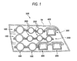
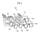
- Figs. 1 and 2 illustrate an example of the structure of a lighting unit 500 for a vehicle according to an exemplary embodiment of the invention.
- Fig. 1 is a front view showing the lighting unit 500 for a vehicle.
- Fig. 2 is a perspective view showing the lighting unit 500 for a vehicle with a transparent cover 400, shown in Fig. 1, removed.
- Fig. 2 is seen from an oblique and forward view.
- longitudinal, transverse and vertical directions are coincident with the longitudinal, transverse and vertical directions of the vehicle, respectively.
- the lighting unit 500 for a vehicle is a headlamp for irradiating, for example, a low beam.
- the lighing unit accommodates a plurality of light source units 100, 200 and 300 in a lamp housing constituted by the transparent cover 400 and a bracket 54.
- the light source units are classified into the first light source unit 100 having a circular shape and having a comparatively large diameter, the second light source unit 200 having a circular shape and having a comparatively small diameter, and the third light source unit 300 which has a rectangular shape.
- Each of the light source units has, as a light source, a semiconductor light emitting unit which will be described below, and each of the light units irradiates a light generated from the semiconductor light emitting unit from the forward part of the vehicle.
- the semiconductor light emitting unit can be, for example, a light emitting diode unit (LED) or a laser diode.
- the light source units are attached to the bracket 54, which can be turned downward at an angle of approximately 0.5 to 0. 6 degrees with respect to the forward part of the vehicle.
- the bracket 54 is tiltably attached to the lighting unit 500 for a vehicle by means of an aiming mechanism for regulating the direction of the optical axis of the light source unit.
- the light source units 100, 200 and 300 have predetermined light distribution patterns.
- the light source units 100, 200, 300 collectively form a light distribution pattern required for the lighting unit 500 for a vehicle.
- Fig. 3 is an exploded perspective view showing the first light source unit 100.
- the first light source unit 100 provides an intense irradiation of light on a comparatively small range in the light distribution pattern of the lighting unit 500 for a vehicle.
- the first light source unit 100 comprises a light emitting module 10a including an LED unit 40 having a semiconductor light emitting unit 44 mounted thereon and an attachment 16a for surrounding and holding the LED unit 40, a light source pedestal 50a for positioning and supporting the light emitting module 10a, a clip 30a for fixing the light emitting module 10a to the light source pedestal 50a, a reflector 80a for reflecting a light emitted from the semiconductor light emitting unit 44 onto the forward part of the lighting unit, a lens 90a for projecting the light reflected by the reflector 80a onto the forward part of the lighting unit, and screws 28 for fastening the reflector 80a and the lens 90a to the light source pedestal 50a.
- the light emitting module 10a holds the LED unit 40 with a part of lower and side surfaces of
- the reflector 80a is an almost dome-shaped member fixed above the semiconductor light emitting unit 44.
- the reflector 80a has, on an inside surface, a reflecting plane having the shape of part of an almost elliptical sphere, with the optical axis of the first light source unit 100 as a central axis of the elliptical sphere.
- the reflecting plane is formed so that a section of the reflecting plane has the shape of almost 1/4 ellipse, in which common vertex is provided rearward from the semiconductor light emitting unit 44.
- the reflector 80a collects a light emitted from the semiconductor light emitting unit 44 and reflects the light forward close to the optical axis of the lens 90a.
- the lens 90a includes a shade 92a on a side of the lens 90a that is provided close to the LED unit 40.
- the shade 92a shields or reflects apart of a light reflected from the reflector 80a, thereby causing a ray forming the light distribution pattern of the first light source unit 100 to be incident on the lens portion.
- the light source pedestal 50a has an assembly reference plane 59.
- the assembly reference plane 59 determines positions in the direction of the optical axis of the reflector 80a and the lens 90a in relation to the direction of irradiation of the lighting unit 500 for a vehicle with high precision with respect to the light source pedestal 50a, and a positioning projection 57 protruded from the assembly reference plane 59 almost perpendicularly.
- the positioning projection 57 determines the positions of the reflector 80a and the lens 90a in a perpendicular direction to the optical axis with high precision.
- all of the LED unit 40, the reflector 80a and the lens 90a can be positioned with respect to the light source pedestal 50a with high precision and are fixed in this state. Consequently, the relative positions of the reflector 80a and the lens 90a with respect to the semiconductor light emitting unit 44 are determined with high precision. Accordingly, the light generated from the semiconductor light emitting unit 44 can be caused to be incident on the lens 90a with high precision, thereby forming a light distribution pattern with high precision in the forward part of the vehicle.
- the reflector 80a and the lens 90a are taken as a non-limiting example of the optical member according to the invention.
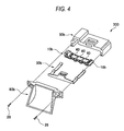
- Fig. 4 is an exploded perspective view showing the third light source unit 300.
- the third light source unit 300 is designed to irradiate a light having the largest range in a transverse direction in the light distribution pattern of the lighting unit 500 for a vehicle.
- the third light source unit 300 includes an oblong light emitting module 10b having a plurality of LED units 40 arranged and mounted in a line, a light source pedestal 50b for positioning the light emitting module 10b thereon in a downward and transverse direction, a clip 30b for fixing the light emitting module 10b with respect to the lower surface of the light source pedestal 50b, and a reflector 80b for irradiating a light emitted downward from the semiconductor light emitting unit 44 over the forward part of the lighting unit 500 for a vehicle.
- the inner reflecting plane of the reflector 80b has a section that is vertical with respect to the longitudinal direction of the lighting unit 500 for a vehicle.
- the vertical section includes a portion that is the shape of an almost 1/4 ellipse.
- the vertex of a major axis of the ellipse is provided in contact with the light source pedestal 50b.
- the whole region of the internal reflecting plane of the reflector is provided behind the semiconductor light emitting unit 44.
- the reflector 80b irradiates lights emitted from the semiconductor light emitting units 44 arranged in the transverse direction over the largest range in the transverse direction in the light distribution pattern of the lighting unit 500 for a vehicle, and furthermore, provides a light within a constant range which is smaller in the vertical direction than that in the transverse direction.
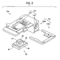
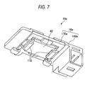
- Figs. 5, 6 and 7 are perspective views showing the light emitting module 10a.
- Figs. 5 and 6 are exploded perspective views showing the light emitting module 10a seen from above and below, respectively.
- Fig. 7 is an assembled perspective view showing the light emitting module 10a seen from below.
- the light emitting module 10a includes the LED unit 40 and the attachment 16a.
- the LED unit 40 has the semiconductor light emitting unit 44, a radiating board 42, and a contact 46.
- the semiconductor light emitting unit 44 is directly fixed to an upper surface of the radiating board 42
- the contact 4 6 formed on the radiating board 42 serves to input a power for causing the semiconductor light emitting unit 44 to emit a light.
- the attachment 16a surrounds and holds the LED unit 40 in a state in which at least a part of the lower and side surfaces of the radiating board 42 and the upper part of the semiconductor light emitting unit 44 are open. In the example, the LED unit 40 is held in a state in which most of the lower surface of the radiating board 42 is exposed.
- the attachment 16a has a power supply portion 162 for supplying a power that causes the semiconductor light emitting unit 44 to emit a light from an external power plug to the contact 46.
- the radiating board 42 is a material having a high thermal conductivity and a low coefficient of thermal expansion, for example, ceramic.
- the radiating board has an almost rectangular shape.
- a pair of contacts 46 are formed on both ends in the longitudinal direction of the radiating board 42 with the semiconductor light emitting unit 44 interposed therebetween.
- the LED unit 40 further has a dome lens 48 fixed to the upper surface of the radiating board 42 and serving to cover the semiconductor light emitting unit 44.
- the dome lens 48 is, for example, a hollow glass lens and has a diameter which is almost equal to that of the side surface of the radiating board 42.
- the light emitting module 10a holds the LED unit 40 in a state in which most of the lower surface of the radiating board 42 is open. Therefore, a heat generated with the light emission of the semiconductor light emitting unit 44 is radiated efficiently. Accordingly, a rise in the temperature of the semiconductor light emitting unit 44 is suppressed and a high light emitting efficiency is obtained. Consequently, it is possible to continuously emit a light having a high luminance. Moreover, the light emitting module 10a holds the LED unit 40 in a state in which at least a part of the side surface of the radiating board 42 is exposed. In the case in which the light emitting module 10a is to be fixed to the lighting unit, consequently, the radiating board 42 can be directly positioned.
- the attachment 16a surrounds and holds the LED unit 40. Therefore, there is no possibility that hands or tools might touch the contact 46 of the LED unit 40, and foreign matters can be prevented from sticking to the contact 46.
- the attachment 16a includes an attachment body 160a and a lower surface support member 170a.
- the attachment body 160a energizes the LED unit 40 downward.
- the lower surface support member 170a is slid and fitted in the attachment body 160a from a side and interposes and holds the LED unit 40 together with the attachment body 160a. According to such a structure, the LED unit 40 can be stably held by the pressing force of the attachment body 160a. Because of the structure in which the lower surface support member 170a is slid and fitted in the attachment body 160a from the side, moreover, the height of the light emitting module 10a can be reduced.
- the attachment body 160a has the power supply portion 1.62.
- the power supply portion 162 includes an input portion 163 connected electrically and a spring terminal 164.
- the input portion 163 acquires a power for causing the semiconductor light emitting unit 44 to emit a light when an external power plug is inserted.
- the spring terminal 164 presses the upper surface of the contact 46 downward and is thus connected electrically to the contact 46, thereby supplying a power for causing the semiconductor light emitting unit 44 to emit a light.
- the positive and negative sides of the spring terminal 164 come in contact with the contact 46 by means of a plurality of independent springs, respectively. Accordingly, the contact 46 and the spring terminal 164 have a highly reliable electrical connection. More specifically, the light emitting module 10a can stably implement the hold of the LED unit 40 and the supply of a power by the energizing force of the spring terminal 164.
- the attachment body 160a has board guides 165 and 166 for positioning the LED unit 40 with respect to the attachment body 160a.
- the board guides 165 and 166 are provided at an almost identical interval to the external shape of the radiating board 42, and the side surfaces of the radiating board 42 are guided by slanted faces provided on their inside surfaces, thereby positioning the LED unit 40.
- the lower surface support member 170a has an almost U shape.
- a tip engagement portion 174 is provided on each of the tips of open ends of the U-shaped lower surface support member, and a rear end engagement portion 176 is provided in a central part on the side opposite the tip engagement portion 174.
- the attachment body 160a is provided with an engagement click 167 engaged with each of the tip engagement portions 174 and serving to hold the tip engagement portion 174 on the attachment body 160a side.
- the attachment body 160a is provided with an engagement click 168 for holding the rear end engagement portion 17 6 on the attachment body 160a side when the engagement click 167 and the tip engagement portion 174 are engaged with each other.
- the lower surface support member 170a further has a contact holding portion 172 for holding the lower surface of the LED unit 40 and maintaining contact between the contact 46 and the spring terminal 164.
- the light emitting module 10a is assembled by following procedure. First, the LED unit 40 is assembled into the attachment body 160a in a state in which the contact 46 of the LED unit 40 is opposed to the spring terminal 164 of the attachment body 160a. Next, the tip engagement portion 174 and the rear end engagement portion 176 are slid to be engaged with the engagement click 167 and the engagement click 168 respectively with the contact holding portion 172 of the lower surface support member 170a placed on a lower side. Consequently, the contact holding portion 172 is guided along the lower surface of the LED unit 40 and the LED unit 40 is fixed in a state shown in Fig. 7. Thus, the assembly of the light emitting module 10a is finished.
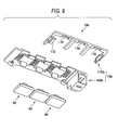
- Figs. 8, 9 and 10 are perspective views showing a light emitting module 10b for mounting a plurality of LED units 40 thereon.
- Figs. 8 and 9 are exploded perspective views showing the light emitting module 10b seen from above and below, respectively.
- Fig. 10 is a perspective view showing a state in which the light emitting module 10b is assembled.
- the light emitting module 10b according to the example has three LED units 40 arranged in a transverse line, the number and array of the LED units 40 is not restricted by the example.
- the structures that are the same as those as the light emitting module 10a shown in Figs. 5, 6 and 7 have been provided the same reference numerals and, therefore, description of these structures will be omitted. Description will be given to different structures from the light emitting module 10a.
- the light emitting module 10b has three LED units 40 and an attachment 16b for surrounding and holding each of the three LED units 40.
- the attachment 16b includes an attachment body 160b and a lower surface support member 170b.
- the attachment body 160b has three pairs of spring terminals 164 for supplying a power to the three LED units 40, respectively. The power is supplied to each of the three pairs of spring terminals 164 through an input portion 163.
- the lower surface support member 170b includes a contact holding portion 172 for supporting the back face of a portion in which the spring terminal 164 and the contact 46 come in contact with each other.
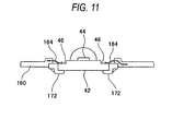
- Fig. 11 is a sectional view taken along the contact 46 and the spring terminal 164 of the light emitting modules 10a and 10b. As shown in Fig. 11, the contact holding portion 172 supports a portion of the lower surface of the radiating board 42 which is opposite the contact 46. Accordingly, it is possible to reliably maintain contact of the spring terminal 164 with the contact 46.
- Fig. 12 is a perspective view showing a state in which the light emitting module 10a is fixed to a light source pedestal 50a with a clip 30a.
- Fig. 13 shows a state in which the clip 30a and the attachment 16a are omitted from Fig. 12.
- the light source pedestal 50a has a positioning portion 56 for directly abutting the side surface of the radiating board 42 in order to position the radiating board 42.
- the light source pedestal also has a support surface 55 for directly coming in contact with the lower surface of the radiating board 42 to support the LED unit 40.
- the light source pedestal 50a has an engagement surface 51 formed almost parallel with the support surface 55 below the support surface 55.
- the clip 30a has a pair of upper surface pressing portions 32 for pressing both left and right ends of the upper surface of the attachment 16a against the light source pedestal 50a.
- the clip 30a also has a lower surface engagement portion 36 to be engaged with the engagement surface 51 shown in Fig. 13.
- Left and right ends of the upper surface of the attachment 16a and the engagement surface 51 are interposed between the upper surface pressing portions 32 and the lower surface engagement portion 36 of the clip 30a, thereby pressing the lower surface of the radiating board 42 against the support surface 55 through the attachment 16a.
- the upper surface of the attachment 16a and the engagement surface 51 being interposed by the portions clip 30a causes the spring terminal 164 to strongly press against the contact 46 . Consequently, it is possible to enhance the reliability of the electrical connection of the contact 46 and the spring terminal 164.
- the light source pedestal 50a has a holding portion 58 for abutting on the upper surface of the tip of the upper surface pressing portion 32.
- the holding portion 58 holds the tip of the upper surface pressing portion 32 so that the light emitting module 10 can be pressed against the light source pedestal 50a more reliably.
- the clip 30a can stably fix the light emitting module 10a to the light source pedestal 50a, and furthermore, a heat generated from the semiconductor light emittingunit 44 can be efficiently radiated to the light source pedestal 50a through the radiating board 42. Consequently, a reduction in the quantity of a light of the semiconductor light emitting unit 44'caused by the heat can be prevented.
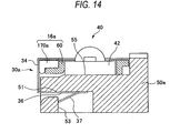
- Figs. 14 and 15 are sectional views showing an A cross-section and a B cross-section of Fig. 12, respectively.
- a cutback 37 is provided on the tip of the lower surface engagement portion 36 of the clip 30a.
- the cutback 37 is engaged with an engagement surface 53 provided vertically below the engagement surface 51 so that the clip 30a is fixed.
- the clip 30a has a side surface pressing portion 34 that abuts the side surface of the attachment 16a.
- the side surface pressing portion 34 presses the side surface of the attachment 16a against the inner part of the light source pedestal 50a (a rightward direction of the drawing) when the cutback 37 is engaged wi th the engagement surface 53.
- the attachment 16a has a regulating rib 60 that abuts a side surface in the radiating board 42, the side surface being provided on the opposite side of radiating board 42 with respect to the positioning portion 56.
- the side surface pressing portion 34 presses the side surface of the attachment 16a against the light source pedestal 50a
- the regulating rib 60 presses the radiating board 42 against the positioning portion 56 as shown in Fig. 15. Consequently, the LED unit 40 is directly positioned so that it abuts the light source pedestal 50a.
- the reference position of the light emitting region of the semiconductor light emitting unit 44 is positioned with high precision in a horizontal direction with respect to the positioning portion 56 of the light source pedestal 50a.
- the reflector 80a and the lens 90a are positioned with high precision with respect to the assembly reference plane 59 and the positioning projection 57 as described above.
- the LED unit 40 is stably fixed to the support surface 55 of the light sourcepedestal 50a in a vertical direction.
- the positions of the reflector 80a and the lens 90a in the vertical direction are determined with high precision by the positioning projection 57 as described above.
- By managing a distance in the vertical direction from the support surface 55 for supporting the LED unit 40 to the positioning projection 57 with high precision it is possible to maintain the relative positions in the vertical direction of the center of the light emitting region of the semiconductor light emitting unit 44 with the reflector 80a and the lens 90a with high precision.
- the relative positions of the light emitting region of the semiconductor light emitting unit 44 with the reflector 80a and the lens 90a are maintained with high precision in both the horizontal and vertical directions of the first light source unit 100,. Accordingly, the first light source unit 100 can irradiate a light generated from the semiconductor-light emitting unit 44 to an outside with high precision.
- the radiating board 42 is mainly made of a material having a high thermal conductivity and a low coefficient of thermal expansion, for example, a metal or ceramic. Therefore, the external shape of the radiating board 42 is not easily changed by the heat generated from the semiconductor light emitting unit 44.
- the relative positions of the light emitting region of the semiconductor light emitting unit 44 with the reflector 80a and the lens 90a are not changed by the generation of the heat of the semiconductor light emitting unit 44 so that the first light source unit 100 can irradiate the light of the semiconductor light emitting unit 44 to the outside with higher precision.
- the relative positions of the reflector 80a and the lens 90a with the semiconductor light emitting unit 44 are maintained with high precision.
- the reference of the semiconductor light emitting unit 44 for example, the center of an optical region is aligned with the optical center of the reflector 80a with high precision. Accordingly, the lighting unit 500 for a vehicle can form a predetermined light distribution pattern with high precision.
- the lighting unit 500 for a vehicle effectively radiates the heat generated from the semiconductor light emitting unit 44 so that a reduction in the luminance of the semiconductor light emitting unit 44 can be prevented.
- the attachment 16 includes a power circuit in the middle of a power supply path between the input portion 163 and the spring terminal 164.
- the power circuit converts a voltage and a current to be supplied from an external power plug to the input portion 163 into a current and a voltage for operating the LED unit 40.
- the power circuit is formed on a circuit board incorporated in the attachment 16.
- the circuit board and the power supply portion 162 are connected to each other through a soft flexible substrate.
- the flexible substrate is a sufficient length for the incorporation and connection of the circuit board. Since the flexible substrate has a predetermined flexure, it can be prevented from being disconnected even if a vibration is applied to the lighting unit 500 for a vehicle.
- the attachment 16 may further include a fail safe circuit or an interface circuit in the middle of the power supply path from the input portion 163 to the spring terminal 164.
- the circuit board is provided apart from the radiating board 42. Accordingly, the temperature of the semiconductor light emitting unit 44 can be prevented from being raised by the heat generated from the power circuit. Moreover, it is desirable that the circuit board should be covered with a metal case having a high thermal conductivity and a high radiating property. Consequently, it is possible to efficiently radiate the heat generated from the power circuit. Furthermore, it is desirable that the metal case should be connected to the ground plane of the circuit board. Consequently, it is possible to effectively block the radiation of a noise generated from the power circuit onto an outside.
- the circuit board should be exchangeable with respect to the attachment 16.
- power circuits having different properties for example, current values
- it is possible to easily implement a light emitting module 10 having a different property while using the same LED unit 40.
- one power circuit By causing one power circuit to correspond to one LED unit 40, thus, it is possible to advantageously standardize the LED unit 40.
Landscapes
- Engineering & Computer Science (AREA)
- General Engineering & Computer Science (AREA)
- Physics & Mathematics (AREA)
- Microelectronics & Electronic Packaging (AREA)
- Optics & Photonics (AREA)
- Non-Portable Lighting Devices Or Systems Thereof (AREA)
- Arrangement Of Elements, Cooling, Sealing, Or The Like Of Lighting Devices (AREA)
- Fastening Of Light Sources Or Lamp Holders (AREA)
Applications Claiming Priority (1)
| Application Number | Priority Date | Filing Date | Title |
|---|---|---|---|
| JP2004244435A JP4350617B2 (ja) | 2004-08-24 | 2004-08-24 | 灯具 |
Publications (3)
| Publication Number | Publication Date |
|---|---|
| EP1630474A2 true EP1630474A2 (de) | 2006-03-01 |
| EP1630474A3 EP1630474A3 (de) | 2008-07-02 |
| EP1630474B1 EP1630474B1 (de) | 2013-10-02 |
Family
ID=34982459
Family Applications (1)
| Application Number | Title | Priority Date | Filing Date |
|---|---|---|---|
| EP05018084.3A Ceased EP1630474B1 (de) | 2004-08-24 | 2005-08-19 | Lichtemittierendes Modul und Beleuchtungseinheit |
Country Status (5)
| Country | Link |
|---|---|
| US (1) | US7290913B2 (de) |
| EP (1) | EP1630474B1 (de) |
| JP (1) | JP4350617B2 (de) |
| KR (1) | KR100646641B1 (de) |
| CN (1) | CN1740632B (de) |
Cited By (9)
| Publication number | Priority date | Publication date | Assignee | Title |
|---|---|---|---|---|
| EP1936263A1 (de) * | 2006-12-18 | 2008-06-25 | Ichikoh Industries, Ltd. | Befestigungsstruktur für eine lichtemittierende Diode |
| EP2131101A1 (de) | 2008-06-02 | 2009-12-09 | odelo GmbH | Leuchte |
| FR2950673A1 (fr) * | 2009-09-30 | 2011-04-01 | Valeo Vision | Support pour source lumineuse de module d'eclairage |
| WO2012136779A1 (de) * | 2011-04-05 | 2012-10-11 | Jb-Lighting Lichtanlagen Gmbh | Scheinwerfer mit leuchtdioden |
| WO2012136637A1 (de) * | 2011-04-05 | 2012-10-11 | Jb-Lighting Lichtanlagentechnik Gmbh | Scheinwerfer mit leuchtdioden |
| EP2673165A4 (de) * | 2011-02-09 | 2014-07-30 | Truck Lite Co Llc | Scheinwerferanordnung mit planarer kühlkörperstruktur |
| EP2317213A3 (de) * | 2009-11-03 | 2015-09-02 | Automotive Lighting Reutlingen GmbH | Leuchtdiodenmodul einer Kraftfahrzeugbeleuchtungseinrichtung und Kraftfahrzeugbeleuchtungseinrichtung |
| WO2017143372A1 (de) * | 2016-02-24 | 2017-08-31 | Zkw Group Gmbh | Halterungsvorrichtung für ein elektronisches bauteil |
| EP2218962A3 (de) * | 2009-02-16 | 2018-04-11 | Koito Manufacturing Co., Ltd. | Lichtquellenmodul und Fahrzeuglampe |
Families Citing this family (54)
| Publication number | Priority date | Publication date | Assignee | Title |
|---|---|---|---|---|
| JP4500273B2 (ja) * | 2006-01-31 | 2010-07-14 | 株式会社小糸製作所 | 車両用前照灯 |
| JP4535453B2 (ja) * | 2006-03-06 | 2010-09-01 | 株式会社小糸製作所 | 光源モジュール及び車輌用灯具 |
| US7440280B2 (en) * | 2006-03-31 | 2008-10-21 | Hong Kong Applied Science & Technology Research Institute Co., Ltd | Heat exchange enhancement |
| US20070230185A1 (en) * | 2006-03-31 | 2007-10-04 | Shuy Geoffrey W | Heat exchange enhancement |
| US7593229B2 (en) * | 2006-03-31 | 2009-09-22 | Hong Kong Applied Science & Technology Research Institute Co. Ltd | Heat exchange enhancement |
| JP2008016362A (ja) * | 2006-07-07 | 2008-01-24 | Koito Mfg Co Ltd | 発光モジュール及び車輌用灯具 |
| JP4702326B2 (ja) * | 2007-06-08 | 2011-06-15 | 市光工業株式会社 | 照明装置用の発光ダイオード固定構造 |
| JP4835605B2 (ja) * | 2008-02-19 | 2011-12-14 | 市光工業株式会社 | 車両用灯具 |
| JP2009199780A (ja) * | 2008-02-19 | 2009-09-03 | Ichikoh Ind Ltd | 車両用灯具 |
| US20090207617A1 (en) * | 2008-02-20 | 2009-08-20 | Merchant Viren B | Light emitting diode (led) connector clip |
| JP5035995B2 (ja) * | 2008-03-21 | 2012-09-26 | 株式会社小糸製作所 | 光源モジュール及び車輌用灯具 |
| JP5232555B2 (ja) | 2008-07-23 | 2013-07-10 | スタンレー電気株式会社 | 光半導体装置モジュール |
| JP5073617B2 (ja) * | 2008-08-27 | 2012-11-14 | 株式会社小糸製作所 | 車両用灯具 |
| JP2010073428A (ja) * | 2008-09-17 | 2010-04-02 | Ichikoh Ind Ltd | 車両用灯具 |
| KR101009786B1 (ko) * | 2008-10-23 | 2011-01-19 | 에프씨산업 주식회사 | Led 조명등 |
| US8651711B2 (en) | 2009-02-02 | 2014-02-18 | Apex Technologies, Inc. | Modular lighting system and method employing loosely constrained magnetic structures |
| JP5409217B2 (ja) * | 2009-09-07 | 2014-02-05 | 株式会社小糸製作所 | 車両用灯具 |
| US8308320B2 (en) | 2009-11-12 | 2012-11-13 | Cooper Technologies Company | Light emitting diode modules with male/female features for end-to-end coupling |
| KR101627866B1 (ko) * | 2009-12-29 | 2016-06-07 | 엘지이노텍 주식회사 | 차량 헤드램프용 액츄에이터 |
| US8616720B2 (en) | 2010-04-27 | 2013-12-31 | Cooper Technologies Company | Linkable linear light emitting diode system |
| WO2011139768A2 (en) | 2010-04-28 | 2011-11-10 | Cooper Technologies Company | Linear led light module |
| JP5570331B2 (ja) | 2010-07-12 | 2014-08-13 | 株式会社小糸製作所 | 車両用灯具 |
| CN103026132A (zh) * | 2010-07-14 | 2013-04-03 | 皇家飞利浦电子股份有限公司 | 具有用于光学器件的安装元件的led照明组件 |
| DE102010033092A1 (de) * | 2010-08-02 | 2012-02-02 | Osram Opto Semiconductors Gmbh | Optoelektronisches Leuchtmodul und Kfz-Scheinwerfer |
| JP5666882B2 (ja) * | 2010-11-18 | 2015-02-12 | 株式会社小糸製作所 | ハイビーム用灯具ユニット |
| US9301416B2 (en) * | 2010-12-15 | 2016-03-29 | Molex, Llc | Energy consuming device and assembly |
| CN103403445B (zh) * | 2011-03-03 | 2016-09-14 | 皇家飞利浦有限公司 | 带有弹簧加载的led保持器的发光装置 |
| JP2011187451A (ja) * | 2011-04-28 | 2011-09-22 | Koito Mfg Co Ltd | 発光モジュール及び車輌用灯具 |
| JP5767853B2 (ja) | 2011-05-12 | 2015-08-19 | 株式会社小糸製作所 | 車両用灯具 |
| KR101240449B1 (ko) | 2011-07-14 | 2013-03-11 | 김정열 | 엘이디 바 그리퍼 |
| JP2013045680A (ja) * | 2011-08-25 | 2013-03-04 | Stanley Electric Co Ltd | 車両用灯具のled基板固定構造 |
| JP5931410B2 (ja) | 2011-11-15 | 2016-06-08 | 株式会社小糸製作所 | 発光モジュールとその製造方法及び車両用灯具 |
| CN104246353B (zh) * | 2012-04-13 | 2017-06-27 | 松下知识产权经营株式会社 | 灯和照明装置 |
| DE102013106451B4 (de) * | 2013-06-20 | 2021-03-25 | HELLA GmbH & Co. KGaA | Lichtmodul mit einem Blendenelement für einen Scheinwerfer eines Fahrzeugs |
| JP5702843B2 (ja) * | 2013-10-30 | 2015-04-15 | 株式会社小糸製作所 | 光源モジュール及び車輌用灯具 |
| EP2915698B1 (de) * | 2014-03-06 | 2021-05-05 | HDO -Druckguss- und Oberflächentechnik GmbH | LED-Leuchte |
| DE102014109114B4 (de) * | 2014-06-30 | 2024-04-25 | HELLA GmbH & Co. KGaA | Anordnung eines Kühlkörpers in einem Scheinwerfer |
| KR200480827Y1 (ko) * | 2014-08-18 | 2016-07-12 | 에스엘 주식회사 | 차량용 램프 어셈블리 |
| FR3026467B1 (fr) * | 2014-09-30 | 2019-10-04 | Valeo Vision | Module lumineux comportant au moins un composant et un connecteur disposes sur un dissipateur de chaleur, et dispositif d'eclairage pour vehicule automobile comportant un tel module |
| FR3026360B1 (fr) * | 2014-09-30 | 2018-03-23 | Valeo Vision | Dispositif de positionnement sur un dispositif optique d'un module comportant une source lumineuse |
| JP6481481B2 (ja) * | 2015-04-20 | 2019-03-13 | 市光工業株式会社 | 車両用灯具 |
| US9903538B2 (en) * | 2015-10-07 | 2018-02-27 | Smk Corporation | Connector for LED module substrate |
| FR3055397B1 (fr) * | 2016-08-30 | 2021-04-30 | Valeo Vision | Module lumineux comportant au moins une source lumineuse amovible |
| US9945541B1 (en) | 2016-12-20 | 2018-04-17 | Keeper Technology Co., Ltd. | Light-emitting diode module holder |
| US10260696B2 (en) * | 2016-12-22 | 2019-04-16 | Keeper Technology Co., Ltd. | Light-emitting diode module holder |
| TWI623700B (zh) * | 2017-07-11 | 2018-05-11 | Light-emitting diode fixing device | |
| US10066800B1 (en) | 2017-09-21 | 2018-09-04 | Keeper Technology Co., Ltd. | Light-emitting diode fixing apparatus |
| KR102551746B1 (ko) | 2018-06-05 | 2023-07-07 | 삼성전자주식회사 | 광원모듈 |
| US11250284B2 (en) * | 2019-09-18 | 2022-02-15 | Veoneer Us, Inc. | Device for emitting radiation |
| KR102252480B1 (ko) | 2020-03-27 | 2021-05-14 | 에스엘 주식회사 | 차량용 램프 및 차량용 램프를 조립하는 방법 |
| KR102322468B1 (ko) | 2019-12-02 | 2021-11-05 | 에스엘 주식회사 | 차량용 램프 및 차량용 램프를 조립하는 방법 |
| KR102313643B1 (ko) | 2020-05-29 | 2021-10-18 | 에스엘 주식회사 | 차량용 램프 및 차량용 램프를 조립하는 방법 |
| US11199317B1 (en) | 2020-08-14 | 2021-12-14 | Scott Fetzer SFEG | Light stick bus system |
| US20240145989A1 (en) * | 2022-10-31 | 2024-05-02 | Valeo North America, Inc. | Supplemental spring lock for connector interface |
Citations (2)
| Publication number | Priority date | Publication date | Assignee | Title |
|---|---|---|---|---|
| JPH0689601A (ja) | 1992-09-04 | 1994-03-29 | Koito Mfg Co Ltd | 車輌用前照灯の反射鏡 |
| WO2004071143A1 (en) | 2003-02-07 | 2004-08-19 | Matsushita Electric Industrial Co., Ltd. | Socket for led light source and lighting system using the socket |
Family Cites Families (7)
| Publication number | Priority date | Publication date | Assignee | Title |
|---|---|---|---|---|
| JP3987257B2 (ja) * | 1999-12-10 | 2007-10-03 | ローム株式会社 | 液晶表示装置 |
| US6582100B1 (en) * | 2000-08-09 | 2003-06-24 | Relume Corporation | LED mounting system |
| US20030099114A1 (en) * | 2001-11-28 | 2003-05-29 | Kazuhiro Ohara | Disk box with flashing circuit |
| JP4080780B2 (ja) * | 2002-04-23 | 2008-04-23 | 株式会社小糸製作所 | 光源ユニット |
| JP2004047351A (ja) * | 2002-07-15 | 2004-02-12 | Koito Mfg Co Ltd | 車両用灯具 |
| JP4194828B2 (ja) | 2002-11-29 | 2008-12-10 | 豊田合成株式会社 | Ledランプ |
| JP4102240B2 (ja) * | 2003-04-08 | 2008-06-18 | 株式会社小糸製作所 | 車両用前照灯 |
-
2004
- 2004-08-24 JP JP2004244435A patent/JP4350617B2/ja not_active Expired - Fee Related
-
2005
- 2005-08-09 US US11/199,248 patent/US7290913B2/en not_active Expired - Lifetime
- 2005-08-19 EP EP05018084.3A patent/EP1630474B1/de not_active Ceased
- 2005-08-23 KR KR1020050077446A patent/KR100646641B1/ko not_active Expired - Fee Related
- 2005-08-24 CN CN2005100930177A patent/CN1740632B/zh not_active Expired - Fee Related
Patent Citations (2)
| Publication number | Priority date | Publication date | Assignee | Title |
|---|---|---|---|---|
| JPH0689601A (ja) | 1992-09-04 | 1994-03-29 | Koito Mfg Co Ltd | 車輌用前照灯の反射鏡 |
| WO2004071143A1 (en) | 2003-02-07 | 2004-08-19 | Matsushita Electric Industrial Co., Ltd. | Socket for led light source and lighting system using the socket |
Cited By (15)
| Publication number | Priority date | Publication date | Assignee | Title |
|---|---|---|---|---|
| EP1936263A1 (de) * | 2006-12-18 | 2008-06-25 | Ichikoh Industries, Ltd. | Befestigungsstruktur für eine lichtemittierende Diode |
| EP2131101A1 (de) | 2008-06-02 | 2009-12-09 | odelo GmbH | Leuchte |
| EP2218962A3 (de) * | 2009-02-16 | 2018-04-11 | Koito Manufacturing Co., Ltd. | Lichtquellenmodul und Fahrzeuglampe |
| US8591053B2 (en) | 2009-09-30 | 2013-11-26 | Valeo Vision | Light source support of lighting module |
| EP2306599A1 (de) | 2009-09-30 | 2011-04-06 | Valeo Vision | Halterung für Lichtquelle eines Beleuchtungsmoduls |
| FR2950673A1 (fr) * | 2009-09-30 | 2011-04-01 | Valeo Vision | Support pour source lumineuse de module d'eclairage |
| EP2317213A3 (de) * | 2009-11-03 | 2015-09-02 | Automotive Lighting Reutlingen GmbH | Leuchtdiodenmodul einer Kraftfahrzeugbeleuchtungseinrichtung und Kraftfahrzeugbeleuchtungseinrichtung |
| EP2673165A4 (de) * | 2011-02-09 | 2014-07-30 | Truck Lite Co Llc | Scheinwerferanordnung mit planarer kühlkörperstruktur |
| EP3260327A1 (de) * | 2011-02-09 | 2017-12-27 | Truck-Lite Co. LLC | Scheinwerferanordnung mit planarer kühlkörperstruktur |
| WO2012136779A1 (de) * | 2011-04-05 | 2012-10-11 | Jb-Lighting Lichtanlagen Gmbh | Scheinwerfer mit leuchtdioden |
| WO2012136637A1 (de) * | 2011-04-05 | 2012-10-11 | Jb-Lighting Lichtanlagentechnik Gmbh | Scheinwerfer mit leuchtdioden |
| US9194543B2 (en) | 2011-04-05 | 2015-11-24 | Jb-Lighting Lichtanlagentechnik Gmbh | Floodlight comprising light-emitting diodes |
| US9696024B2 (en) | 2011-04-05 | 2017-07-04 | Jb-Lighting Lichtanlagentechnik Gmbh | Headlight comprising light-emitting diodes |
| WO2017143372A1 (de) * | 2016-02-24 | 2017-08-31 | Zkw Group Gmbh | Halterungsvorrichtung für ein elektronisches bauteil |
| US10429024B2 (en) | 2016-02-24 | 2019-10-01 | Zkw Group Gmbh | Retaining device for an electronic component |
Also Published As
| Publication number | Publication date |
|---|---|
| EP1630474A3 (de) | 2008-07-02 |
| CN1740632B (zh) | 2010-06-16 |
| JP4350617B2 (ja) | 2009-10-21 |
| CN1740632A (zh) | 2006-03-01 |
| KR100646641B1 (ko) | 2006-11-23 |
| EP1630474B1 (de) | 2013-10-02 |
| US7290913B2 (en) | 2007-11-06 |
| US20060044840A1 (en) | 2006-03-02 |
| JP2006066108A (ja) | 2006-03-09 |
| KR20060050580A (ko) | 2006-05-19 |
Similar Documents
| Publication | Publication Date | Title |
|---|---|---|
| EP1630474B1 (de) | Lichtemittierendes Modul und Beleuchtungseinheit | |
| CN1644978B (zh) | 灯具 | |
| JP5570331B2 (ja) | 車両用灯具 | |
| JP5746930B2 (ja) | 車両用灯具 | |
| US7665872B2 (en) | Vehicle headlamp | |
| US7985014B2 (en) | Light source module | |
| JP4593661B2 (ja) | 車両用灯具 | |
| US9267655B2 (en) | Vehicle lamp | |
| JP2005044698A (ja) | 車両用灯具及び光源モジュール | |
| JP2005044699A (ja) | 車両用灯具及び光源モジュール | |
| JP2005209538A (ja) | 灯具 | |
| JP4295126B2 (ja) | 灯具 | |
| JP5749837B2 (ja) | 光源固定用アタッチメント | |
| JP2005209537A (ja) | 灯具 | |
| JP4523030B2 (ja) | 車両用灯具 | |
| JP4523031B2 (ja) | 車両用灯具 | |
| JP2018081935A (ja) | アタッチメントおよび照明装置 |
Legal Events
| Date | Code | Title | Description |
|---|---|---|---|
| PUAI | Public reference made under article 153(3) epc to a published international application that has entered the european phase |
Free format text: ORIGINAL CODE: 0009012 |
|
| AK | Designated contracting states |
Kind code of ref document: A2 Designated state(s): AT BE BG CH CY CZ DE DK EE ES FI FR GB GR HU IE IS IT LI LT LU LV MC NL PL PT RO SE SI SK TR |
|
| AX | Request for extension of the european patent |
Extension state: AL BA HR MK YU |
|
| PUAL | Search report despatched |
Free format text: ORIGINAL CODE: 0009013 |
|
| AK | Designated contracting states |
Kind code of ref document: A3 Designated state(s): AT BE BG CH CY CZ DE DK EE ES FI FR GB GR HU IE IS IT LI LT LU LV MC NL PL PT RO SE SI SK TR |
|
| AX | Request for extension of the european patent |
Extension state: AL BA HR MK YU |
|
| 17P | Request for examination filed |
Effective date: 20081027 |
|
| AKX | Designation fees paid |
Designated state(s): DE FR GB |
|
| 17Q | First examination report despatched |
Effective date: 20101213 |
|
| GRAP | Despatch of communication of intention to grant a patent |
Free format text: ORIGINAL CODE: EPIDOSNIGR1 |
|
| INTG | Intention to grant announced |
Effective date: 20130423 |
|
| GRAS | Grant fee paid |
Free format text: ORIGINAL CODE: EPIDOSNIGR3 |
|
| GRAA | (expected) grant |
Free format text: ORIGINAL CODE: 0009210 |
|
| AK | Designated contracting states |
Kind code of ref document: B1 Designated state(s): DE FR GB |
|
| REG | Reference to a national code |
Ref country code: GB Ref legal event code: FG4D |
|
| REG | Reference to a national code |
Ref country code: DE Ref legal event code: R096 Ref document number: 602005041364 Country of ref document: DE Effective date: 20131128 |
|
| REG | Reference to a national code |
Ref country code: DE Ref legal event code: R097 Ref document number: 602005041364 Country of ref document: DE |
|
| PLBE | No opposition filed within time limit |
Free format text: ORIGINAL CODE: 0009261 |
|
| STAA | Information on the status of an ep patent application or granted ep patent |
Free format text: STATUS: NO OPPOSITION FILED WITHIN TIME LIMIT |
|
| 26N | No opposition filed |
Effective date: 20140703 |
|
| REG | Reference to a national code |
Ref country code: DE Ref legal event code: R097 Ref document number: 602005041364 Country of ref document: DE Effective date: 20140703 |
|
| PGFP | Annual fee paid to national office [announced via postgrant information from national office to epo] |
Ref country code: GB Payment date: 20140813 Year of fee payment: 10 |
|
| GBPC | Gb: european patent ceased through non-payment of renewal fee |
Effective date: 20150819 |
|
| REG | Reference to a national code |
Ref country code: FR Ref legal event code: PLFP Year of fee payment: 12 |
|
| PG25 | Lapsed in a contracting state [announced via postgrant information from national office to epo] |
Ref country code: GB Free format text: LAPSE BECAUSE OF NON-PAYMENT OF DUE FEES Effective date: 20150819 |
|
| REG | Reference to a national code |
Ref country code: FR Ref legal event code: PLFP Year of fee payment: 13 |
|
| REG | Reference to a national code |
Ref country code: FR Ref legal event code: PLFP Year of fee payment: 14 |
|
| PGFP | Annual fee paid to national office [announced via postgrant information from national office to epo] |
Ref country code: DE Payment date: 20190806 Year of fee payment: 15 Ref country code: FR Payment date: 20190711 Year of fee payment: 15 |
|
| REG | Reference to a national code |
Ref country code: DE Ref legal event code: R119 Ref document number: 602005041364 Country of ref document: DE |
|
| PG25 | Lapsed in a contracting state [announced via postgrant information from national office to epo] |
Ref country code: FR Free format text: LAPSE BECAUSE OF NON-PAYMENT OF DUE FEES Effective date: 20200831 Ref country code: DE Free format text: LAPSE BECAUSE OF NON-PAYMENT OF DUE FEES Effective date: 20210302 |