EP1630492A2 - Temperaturregeleinheit und dieser benutzender Behälter - Google Patents
Temperaturregeleinheit und dieser benutzender Behälter Download PDFInfo
- Publication number
- EP1630492A2 EP1630492A2 EP05015587A EP05015587A EP1630492A2 EP 1630492 A2 EP1630492 A2 EP 1630492A2 EP 05015587 A EP05015587 A EP 05015587A EP 05015587 A EP05015587 A EP 05015587A EP 1630492 A2 EP1630492 A2 EP 1630492A2
- Authority
- EP
- European Patent Office
- Prior art keywords
- temperature controlling
- lid
- container
- insulating container
- controlling unit
- Prior art date
- Legal status (The legal status is an assumption and is not a legal conclusion. Google has not performed a legal analysis and makes no representation as to the accuracy of the status listed.)
- Withdrawn
Links
Images


Classifications
-
- F—MECHANICAL ENGINEERING; LIGHTING; HEATING; WEAPONS; BLASTING
- F25—REFRIGERATION OR COOLING; COMBINED HEATING AND REFRIGERATION SYSTEMS; HEAT PUMP SYSTEMS; MANUFACTURE OR STORAGE OF ICE; LIQUEFACTION SOLIDIFICATION OF GASES
- F25D—REFRIGERATORS; COLD ROOMS; ICE-BOXES; COOLING OR FREEZING APPARATUS NOT OTHERWISE PROVIDED FOR
- F25D19/00—Arrangement or mounting of refrigeration units with respect to devices or objects to be refrigerated, e.g. infrared detectors
- F25D19/003—Arrangement or mounting of refrigeration units with respect to devices or objects to be refrigerated, e.g. infrared detectors with respect to movable containers
-
- F—MECHANICAL ENGINEERING; LIGHTING; HEATING; WEAPONS; BLASTING
- F25—REFRIGERATION OR COOLING; COMBINED HEATING AND REFRIGERATION SYSTEMS; HEAT PUMP SYSTEMS; MANUFACTURE OR STORAGE OF ICE; LIQUEFACTION SOLIDIFICATION OF GASES
- F25B—REFRIGERATION MACHINES, PLANTS OR SYSTEMS; COMBINED HEATING AND REFRIGERATION SYSTEMS; HEAT PUMP SYSTEMS
- F25B9/00—Compression machines, plants or systems, in which the refrigerant is air or other gas of low boiling point
- F25B9/14—Compression machines, plants or systems, in which the refrigerant is air or other gas of low boiling point characterised by the cycle used, e.g. Stirling cycle
-
- F—MECHANICAL ENGINEERING; LIGHTING; HEATING; WEAPONS; BLASTING
- F25—REFRIGERATION OR COOLING; COMBINED HEATING AND REFRIGERATION SYSTEMS; HEAT PUMP SYSTEMS; MANUFACTURE OR STORAGE OF ICE; LIQUEFACTION SOLIDIFICATION OF GASES
- F25D—REFRIGERATORS; COLD ROOMS; ICE-BOXES; COOLING OR FREEZING APPARATUS NOT OTHERWISE PROVIDED FOR
- F25D11/00—Self-contained movable devices, e.g. domestic refrigerators
-
- F—MECHANICAL ENGINEERING; LIGHTING; HEATING; WEAPONS; BLASTING
- F25—REFRIGERATION OR COOLING; COMBINED HEATING AND REFRIGERATION SYSTEMS; HEAT PUMP SYSTEMS; MANUFACTURE OR STORAGE OF ICE; LIQUEFACTION SOLIDIFICATION OF GASES
- F25D—REFRIGERATORS; COLD ROOMS; ICE-BOXES; COOLING OR FREEZING APPARATUS NOT OTHERWISE PROVIDED FOR
- F25D19/00—Arrangement or mounting of refrigeration units with respect to devices or objects to be refrigerated, e.g. infrared detectors
- F25D19/02—Arrangement or mounting of refrigeration units with respect to devices or objects to be refrigerated, e.g. infrared detectors plug-in type
-
- F—MECHANICAL ENGINEERING; LIGHTING; HEATING; WEAPONS; BLASTING
- F25—REFRIGERATION OR COOLING; COMBINED HEATING AND REFRIGERATION SYSTEMS; HEAT PUMP SYSTEMS; MANUFACTURE OR STORAGE OF ICE; LIQUEFACTION SOLIDIFICATION OF GASES
- F25D—REFRIGERATORS; COLD ROOMS; ICE-BOXES; COOLING OR FREEZING APPARATUS NOT OTHERWISE PROVIDED FOR
- F25D2323/00—General constructional features not provided for in other groups of this subclass
- F25D2323/06—Details of walls not otherwise covered
- F25D2323/061—Collapsible walls
Definitions
- the present invention relates to a temperature controlling unit and a container using the same, and more particularly, to a container for transportation.
- a conventional container for transportation comprises an insulating container and a cover, both made of foam synthetic resins, and holds solid carbon dioxide, a cold reserving agent or the like inside, thereby cooling the interior of the container.
- Japanese Unexamined Patent Publication No. 2000-304402 discloses an electronic cooling or heating container comprising an insulating container with an openable and closable lid, in which the insulating container has a built-in cooling or heating unit (corresponding to a temperature controlling unit of the present invention).
- 2553022 discloses a cooling or heating container with a lid which openably and closably covers the opening of an insulating box (corresponding to an insulating container of the present invention), and has a built-in cooling or heating apparatus (corresponding to the temperature controlling unit of the present invention).
- Japanese Unexamined Patent Publication No. 2001-311576 discloses a cooling box with a lid which openably and closably covers the opening of a box (corresponding to the insulating container of the present invention), and has a built-in a cooling apparatus (corresponding to the temperature controlling unit of the present invention).
- the container which cools the interior by solid carbon dioxide, a cold reserving agent or the like has a problem such that as solid carbon dioxide sublimes or the cold reserving agent melts down due to heat from stored items or heat from the exterior of the container, it takes a lot of trouble for refilling solid carbon dioxide or replacing the cold reserving agent to keep the stored items in the container for a long time.
- solid carbon dioxide its repetitive use over a long period of time increases not only the amount of the solid carbon dioxide, which eventually increases the running cost, but also the density of carbon dioxide in the atmosphere as the solid carbon dioxide gasifies due to the sublimation.
- the present invention has been made to solve the aforementioned problems, and it is an object of the present invention to provide a container which enables storage of items for a long period at low running cost and allows its volume to be set relatively freely, and a temperature controlling unit which constitutes the container.
- Another object of the present invention is to provide a relatively lightweight and inexpensive container as well as a temperature controlling unit which constitutes the container.
- a temperature controlling unit is a temperature controlling unit which comprises: an insulative lid; and a temperature controlling subunit which includes a temperature controlling device provided on the lid, and includes a temperature control effect member which is thermally exposed at one surface side of the lid.
- the temperature controlling subunit may further include an attachment member for attaching the temperature controlling subunit to the lid.
- the temperature controlling device may include a Stirling refrigerator.
- a container according to a second aspect of the present invention is a container which comprises: an insulating container which has an opening; and the aforementioned temperature controlling unit which is independent of the insulating container, wherein the temperature controlling unit is detachably attached to the opening of the insulating container in such a manner as to close and seal the opening.
- the lid and the insulating container may be made of foam synthetic resins.
- the opening of the insulating container may be openable and closable selectively by the temperature controlling unit or an insulative second lid.
- the temperature control effect member may be thermally exposed at the interior of the insulating container.
- the temperature controlling device may include a Stirling refrigerator.
- a temperature controlling unit is a temperature controlling unit which comprises: an insulative main lid; an insulative sub-lid; and a temperature controlling subunit which includes a temperature controlling device provided on the sub-lid, wherein the temperature controlling subunit includes a temperature control effect member which is thermally exposed at one surface side of the sub-lid.
- the temperature controlling subunit may further include an attachment member for attaching the temperature controlling subunit to the sub-lid.
- the temperature controlling device may include a Stirling refrigerator.
- a container according to a fourth aspect of the present invention is a container which comprises: an insulating container which has an opening; and the temperature controlling unit which is independent of the insulating container, wherein the sub-lid of the temperature controlling unit is detachably attached to the opening of the insulating container in such a manner as to close and seal a portion of the opening, and the main lid of the temperature controlling unit is attached to the opening of the insulating container in such a manner as to close and seal an other portion of the opening.
- the main lid, the sub-lid and the insulating container may be made of foam synthetic resins.
- the temperature controlling device may include a Stirling refrigerator.
- a temperature controlling unit is a temperature controlling unit which comprises: a frame which has an opening; an insulative main lid so attached to the frame as to freely open and close a portion of the opening of the frame; an insulative sub-lid so attached to the frame as to cover the other portion of the opening of the frame; and a temperature controlling subunit which is attached to said sub-lid, and includes a Stirling refrigerator, wherein the temperature controlling subunit includes a temperature control effect member thermally exposed at one surface side of the sub-lid.
- the temperature controlling subunit may further include an attachment member for attaching the temperature controlling subunit to the sub-lid.
- a container according to the sixth aspect of the present invention is a container which comprises: an insulating container which has an opening: and the temperature controlling unit which is independent of the insulating container, and is detachably attached to the opening of the insulating container in such a manner as to close and seal the opening.
- the main lid, the sub-lid and the insulating container may be made of insulative materials in tabular shapes.
- the frame may be made of a low heat-conductive material.
- the insulating container may have a foldable structure.
- the main lid and the sub-lid may be covered by an infrared reflection film.
- Reference number 1 denotes a container, and the container 1 comprises a temperature controlling unit 2 and an insulating container 3.
- the temperature controlling unit 2 comprises a lid 4 formed with a through-hole 4A in a substantial center thereof, and a temperature controlling subunit 5.
- the lid 4 is made of an insulative foam synthetic resin in a tabular shape, in a single-piece manner, and its entire surface is covered with an infrared reflection film as an infrared reflection layer.
- a step member 4B is formed on the through-hole 4A, and a later described base 8 of the temperature controlling subunit 5 is placed on the step member 4B.
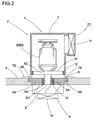
- the temperature controlling subunit 5 comprises a Stirling refrigerator 6 as a temperature controlling device, a casing 7 for containing the Stirling refrigerator 6, and the base 8 for supporting the Stirling refrigerator 6 and the casing 7.
- the Stirling refrigerator 6 is set up side down.
- a heat absorbing sink 9 is attached to a heat absorbing portion 6B, formed on a leading end of a cylindrical portion 6A of the Stirling refrigerator 6, in a heat-conductive manner, and a heat exhausting sink 10 is attached to a heat exhausting portion 6C formed on a base end of the cylindrical portion 6A in a heat-conductive manner.
- the heat absorbing sink 9 is attached to a lower surface side of the base 8 in an exposed manner, and the heat exhausting sink 10 is arranged in the interior of the casing 7.
- a lower portion of the casing 7 is formed with an opening 7A for air intake and an attachment member 7B for fixing the temperature controlling subunit 5.
- An upper portion thereof is formed with an opening 7C for air exhaust, and a fan 11 is attached to the opening 7C.
- a sealing member 12 is provided in between the outer circumference of the heat exhausting sink 10 and the inner wall of the casing 7, so that the space can be sealed.
- a substantial center of the base 8 is formed with a through-hole 8A, and the outer circumference of the base 8 is formed with a step member 8B in association with the step member 4B, so that the base 8 can fit into the through-hole 4A.
- the inner diameter of the through-hole 8A is larger than the outer diameter of the cylindrical portion 6A of the Stirling refrigerator 6, and space between the cylindrical portion 6A and the through-hole 8A is sealed by a sealing member 13 which is made of an insulative foam rubber or the like.
- the heat absorbing sink 9 is so formed as to have a size not to protrude from the outer circumference of a lower portion of the base 8.
- a fan 14 is so provided adjacent to the heat absorbing sink 9 as to allow airflow to pass through the heat absorbing sink 9.
- a temperature control effect member A is structured by the heat absorbing portion 6B of the Stirling refrigerator 6, the heat absorbing sink 9 and the fan 14.
- An operating member 15 is provided on a front side of the casing 7, and a non-illustrated controlling circuit is accommodated in the operating member 15.
- the insulating container 3 is so structured as to include a right wall 3A, a left wall 3B, a front wall 3C, a rear wall 3D, a bottom wall 3E and a lid 16 for the insulating container 3 as a second lid.
- Each of the walls 3A, 3B, 3C, 3D, 3E, and lid 16 is made of an insulative foam synthetic resin in a tabular shape, in a single-piece manner, and each of the entire surfaces is covered with an infrared reflection film as an infrared reflection layer.
- the surfaces of the walls 3A, 3B, 3C, 3D and 3E to be the outside surface of the container are covered with a cover 17 made of an infrared reflection film.
- the edge of the lid 16 is attached to an upper end of the cover 17. According to the aforementioned structure, it is possible to easily and inexpensively manufacture the insulating container 3 of an arbitrary size.
- the temperature controlling subunit 5 is assembled.
- the heat exhausting sink 10 is attached to the heat exhausting portion 6C of the Stirling refrigerator 6, and the sealing member 13 is attached to the outer circumference between the heat absorbing portion 6B and the heat exhausting portion 6C in the cylindrical portion 6A.
- the sealing member 12 is attached to the circumference of the heat exhausting sink 10, the Stirling refrigerator 6 is accommodated in the casing 7 with the Stirling refrigerator 6 being in a handstand condition.
- the fan 11 is attached to the exhausting opening 7C of the casing 7.
- the casing 7 accommodating the Stirling refrigerator 6 is attached to the base 8 by the attachment member 7B, and the cylindrical portion 6A of the Stirling refrigerator 6 is fit through the through-hole 8A of the base 8. At this time, the space between the through-hole 8A and the cylindrical portion 6A is sealed by the sealing member 13.
- the heat absorbing sink 9 is attached to the heat absorbing portion 6B formed on the leading end of a cylindrical portion 6A of the Stirling refrigerator 6, and the fan 14 is attached to adjacent to the heat absorbing sink 9. Electrical wirings of the Stirling refrigerator 6, the fans 11 and 14 are connected to the non-illustrated controlling circuit, and the controlling circuit is accommodated in the operating member 15.
- the temperature controlling subunit 5 is assembled thus way.
- the assembled temperature controlling subunit 5 is attached to the through-hole 4A of the lid 4.
- the base 8 is fitted in and engaged with the through-hole 4A in such a manner as to allow the step member 8B formed on the base 8 of the temperature controlling subunit 5 to mount the step 4B of the through-hole 4A, whereby the temperature controlling subunit 5 is attached to the lid 4.
- the heat absorbing sink 9 since the heat absorbing sink 9 is formed to have the size not to protrude from the outer circumference of the lower portion of the base 8, the heat absorbing sink 9 does not interfere with the through-hole 4A when the temperature controlling subunit 5 is attached to the lid 4.
- the temperature controlling unit 2 is structured by attaching the temperature controlling subunit 5 to the lid 4 thus way, it is possible to obtain the temperature controlling units 2 of various sizes, that is, the temperature controlling units 2 that can match the insulating containers 3 of various sizes, by using the common temperature controlling subunit 5 and changing the lid 4 only.
- the lid 4 is covered with an infrared reflection film, but basically made of an insulative foam synthetic resin in a tabular shape, in a single-piece manner, and thus the lids 4 of various sizes can be easily and inexpensively obtained. Accordingly, it is possible to manufacture the temperature controlling unit 2 inexpensively.
- the heat absorbing portion 6B brought into the low temperature state absorbs heat from the heat absorbing sink 9 thermally contacting the heat absorbing portion 6B and the air inside the insulating container 3 where the heat absorbing sink 9 is exposed, and conducts this absorbed heat to the heat exhausting portion 6C.
- the heat conducted to the heat exhausting portion 6C is exhausted from the heat exhausting sink 10. As the air inside the insulating container 3 is allowed to flow the heat absorbing sink 9 by the fan 14, it is evenly and efficiently cooled by the Stirling refrigerator 6.
- the insulating container 3 itself is made of a light foam synthetic resin in a tabular shape and an infrared reflection film, it has an extremely light-weight structure, and the temperature controlling unit 2 also has a relatively light-weight structure as including the lid 4 made of a foam synthetic resin in a tabular shape and an infrared reflection film, and the temperature controlling subunit 5 using the relatively light Stirling refrigerator 6. Accordingly, the container 1 using the temperature controlling unit 2 as a whole can have a relatively light-weight structure.
- the interior of the container 1 can be not only efficiently cooled, but also cooled to a very low temperature.
- the temperature controlling unit 2 may be detached and the opening 3F of the insulating container 3 may be closed and sealed by the lid 16 of the insulating container 3, when the cooling of the temperature controlling unit 2 is not required.
- the temperature controlling subunit 5, using the Stirling refrigerator 6 as the temperature controlling device is attached to the insulative lid 4, and the heat absorbing sink 9, forming the temperature control effect member A of the temperature control subunit 5, is thermally exposed at one side of the lid 4 as to work as the temperature controlling unit 2, whereby the interior of the insulating container 3 of an arbitrary size, with the opening 3F closed and sealed by the temperature controlling unit 2, can be cooled, and thus items to be stored can be continuously stored for a longer time compared with solid carbon dioxide and a cold reserving agent conventionally used.
- the first embodiment of the present invention not only enables the lid 4 and further the entire temperature controlling unit 2 to be light and inexpensive, but also allows the lid 4 to be easily structured in an arbitrary size.
- the Stirling refrigerator 6 is attached to the lid 4 together with the temperature controlling subunit 5 by the attachment member 7B, whereby the temperature controlling units 2 of various sizes can be easily assembled by attaching the common temperature controlling subunit 5 to the lids 4 of various sizes.
- the running cost can be reduced, and environmental burden can be suppressed as gasified carbon dioxide is not generated.
- Making the insulating container 3 of foam synthetic resin can make the insulating container 3 light and inexpensive. Accordingly, not only the whole container 1 can be made light and inexpensive, but also the insulating container 3 can be easily structured in an arbitrary size.
- the temperature controlling unit 2 in transporting the container 1 whose interior is cooled by the temperature controlling unit 2, by manpower, the temperature controlling unit 2 may be detached and the opening 3F of the insulating container 3 may be closed and sealed by the lid 16 of the insulating container 3, when the cooling of the temperature controlling unit 2 is not required, whereby the container 1 as a whole when transported by manpower can be made lighter.
- the temperature controlling device is the Stirling refrigerator 6 which is small in size and light, and able to cool the interior of the container 1 to a very low temperature at low power, the interior of the container 1 can be cooled to a very low temperature at a low running cost, and the container 1 as a whole can have a light-weight structure.
- a temperature controlling unit 21 of a container 20 comprises a lid 22 formed with a through-hole 22A on a substantial center thereof, and a temperature controlling subunit 23.
- the lid 22 is made of an insulative foam synthetic resin in a tabular shape, in a single-piece manner, and its entire surface is covered with an infrared reflection film as an infrared reflection layer.
- a step member 22B is formed on the through-hole 22A, and a later described base 25 of the temperature controlling subunit 23 is placed on the step member 22B.
- the temperature controlling subunit 23 is so comprised as to include the Stirling refrigerator 6 as the temperature controlling device, a casing 24 for containing the Stirling refrigerator 6, and the base 25 for supporting the Stirling refrigerator 6 and the casing 24.
- the Stirling refrigerator 6 is laterally supported, a heat absorbing sink 27 is attached to the heat absorbing portion 6B, formed on the leading end of the cylindrical portion 6A of the Stirling refrigerator 6, in a heat-conductive manner via a heat conductive block 26, and the heat exhausting sink 10 is attached to the heat exhausting portion 6C formed on the base end of the cylindrical portion 6A in a heat-conductive manner.
- the heat absorbing sink 27 is attached to a lower surface side of the base 25 in an exposed manner, and the heat exhausting sink 10 is arranged inside the casing 24.
- the heat absorbing portion 6B and the heat conductive block 26 are covered with an insulating material 28 inside the casing 24.
- the casing 24 is formed with an opening 24A for air intake on a cylindrical portion 6A side of the Stirling refrigerator 6.
- a lower portion of the casing 24 is formed with an attachment member 24B for fixing the temperature controlling subunit 23.
- a body portion 6D side of the Stirling refrigerator 6 of the casing 24 is formed with opening 24C for air exhaust, and the fan 11 is attached to the opening 24C.
- a through-hole 24D for allowing the heat conductive block 26 to pass through is formed on a lower portion of the casing 24 adjacent to the cylindrical portion 6A of the Stirling refrigerator 6.
- the sealing member 12 is provided in between the outer circumference of the heat exhausting sink 10 and the inner wall of the casing 24, so that the space can be sealed.
- the base 25 is formed with a through-hole 25A in association with the heat conductive block 26, and the outer circumference of the base 25 is formed with a step member 25B in association with the step member 22B, so that the base 25 can fit into the through-hole 22A.
- the inner size of the through-hole 25A is larger than the outer size of the heat conductive block 26, and space between the heat conductive block 26 and the through-hole 25A is sealed by a sealing member 29 which is made of an insulative foam rubber or the like.
- the heat absorbing sink 27 is so formed as to have a size not to protrude from the outer circumference of a lower portion of the base 25.
- the fan 14 is so provided adjacent to the heat absorbing sink 27 as to allow airflow to pass through the heat absorbing sink 27.
- a temperature control effect member B is structured by the heat absorbing portion 6B of the Stirling refrigerator 6, the heat conductive block 26, the heat absorbing sink 27 and the fan 14.
- a non-illustrated operating member is provided on a front side of the casing 24, and a non-illustrated controlling circuit is accommodated in the operating member.
- the temperature controlling subunit 23 is assembled.
- the heat exhausting sink 10 is attached to the heat exhausting portion 6C of the Stirling refrigerator 6,
- the heat conductive block 26 is attached to the heat absorbing portion 6B of the cylindrical portion 6A, and the outer circumferences of the heat absorbing portion 6B and the heat conductive block 26 are covered with the insulating material 28 and the sealing member 29.
- the sealing member 12 is attached to the circumference of the heat exhausting sink 10, the Stirling refrigerator 6 is laterally accommodated in the casing 24.
- the heat conductive block 26 is allowed to pass through the through-hole 24D.
- the fan 11 is attached to the exhausting opening 24C of the casing 24.
- the casing 24 accommodating the Stirling refrigerator 6 is attached to the base 25 by the attachment member 24B, and the heat conductive block 26 is fit through the through-hole 25A of the base 25. At this time, the space between the through-hole 25A and the heat conductive block 26 is sealed by the sealing member 29.
- the heat absorbing sink 27 is attached to a lower end of the heat conductive block 26, and the fan 14 is attached to adjacent to the heat absorbing sink 27.
- the electrical wirings of the Stirling refrigerator 6, the fans 11 and 14 are connected to the non-illustrated controlling circuit, and the controlling circuit is accommodated in the non-illustrated operating member.
- the temperature controlling subunit 23 is assembled thus way. The assembled temperature controlling subunit 23 is attached to the through-hole 22A of the lid 22.
- the base 25 is fitted in and engaged with the through-hole 22A in such a manner as to allow the step member 25B formed on the base 25 of the temperature controlling subunit 23 to mount the step 22B of the through-hole 22A, whereby the temperature controlling subunit 23 is attached to the lid 22.
- the heat absorbing sink 27 is formed to have the size not to protrude from the outer circumference of the lower portion of the base 25, the heat absorbing sink 27 does not interfere with the through-hole 22A when the temperature controlling subunit 23 is attached to the lid 22.
- the temperature controlling unit 21 is structured by attaching the temperature controlling subunit 23 to the lid 22 thus way, it is possible to obtain the temperature controlling units 21 of various sizes, that is, the temperature controlling units 21 that can match the insulating containers 3 of various sizes, by using the common temperature controlling subunit 23 and changing the lid 22 only.
- the lid 22 is covered with an infrared reflection film, but basically made of an insulative foam synthetic resin in a tabular shape, in a single-piece manner, and thus the lids 22 of various sizes can be easily and inexpensively obtained. Accordingly, it is possible to manufacture the temperature controlling unit 21 inexpensively.
- the operation of the second embodiment will now be explained.
- items which were refrigerated or frozen beforehand by a refrigerator or a freezer is taken in the insulating container 3, and the temperature controlling unit 21 is attached to the opening 3F of the insulating container 3.
- the temperature controlling unit 21 is so attached as to allow the heat absorbing sink 27 and the fan 14 to be in the interior of the insulating container 3.
- the non-illustrated operating member is operated, thereby operating the Stirling refrigerator 6 and the fans 11, 14.
- the heat absorbing portion 6B is brought into a low temperature state
- the heat exhausting portion 6C is brought into a high temperature state.
- the heat absorbing portion 6B brought into the low temperature state absorbs heat from the heat conductive block 26 and the heat absorbing sink 27 both thermally contacting the heat absorbing portion 6B and the air inside the insulating container 3 where the heat absorbing sink 27 is exposed, and conducts this absorbed heat to the heat exhausting portion 6C.
- the heat conducted to the heat exhausting portion 6C is exhausted from the heat exhausting sink 10. As the air inside the insulating container 3 is allowed to flow the heat absorbing sink 27 by the fan 14, it is evenly and efficiently cooled by the Stirling refrigerator 6.
- the insulating container 3 itself is made of a light foam synthetic resin in a tabular shape and an infrared reflection film, it has an extremely light-weight structure, and the temperature controlling unit 21 also has a relatively light-weight structure as including the lid 22 made of a foam synthetic resin in a tabular shape and an infrared reflection film, and the temperature controlling subunit 23 using the relatively light Stirling refrigerator 6. Accordingly, the container 20 using the temperature controlling unit 21 as a whole can have a relatively light-weight structure.
- the interior of the container 20 can be not only efficiently cooled, but also cooled to a very low temperature.
- Reference number 30 denotes a container, and the container 30 comprises a temperature controlling unit 31 and a lid 32.
- the lid 32 is made of an insulative foam synthetic resin in a tabular shape, in a single-piece manner, and its entire surface is covered with an infrared reflection film as an infrared reflection layer.
- the lid 32 is openably and closably attached to an opening 33F of a later described insulating container 33 which constitutes the temperature controlling unit 31.
- the temperature controlling unit 31 comprises an insulating container 33 and the temperature controlling subunit 23.
- the insulating container 33 is so structured as to include a right wall 33A, a left wall 33B, a front wall (not illustrated), a rear wall 33D and a bottom wall 33E.
- Each of the walls 33A, 33B, 33D, 33E, and non-illustrated front wall is made of an insulative foam synthetic resin in a tabular shape, in a single-piece manner, and each of the entire surfaces is covered with an infrared reflection film as an infrared reflection layer.
- the surfaces of the walls 33A, 33B, 33D, and 33E, and the non-illustrated front wall to be the outside surface of the container are covered with a cover 34 made of an infrared reflection film.
- the right wall 33A is formed with a through-hole 33G
- the through-hole 33G is formed with a step member 33H
- the step member 25B formed on the outer circumference of the base 25 of the temperature controlling subunit 23 contact the step member 33H in association with the step member 33H, so that the base 25 can fit into the through-hole 33G.
- the Stirling refrigerator 6 inside thereof is in a standing condition, other structures thereof are the same as those of the second embodiment.
- the temperature controlling subunit 23 is assembled.
- the assembling of the temperature controlling subunit 23 is the same as that of the second embodiment.
- the assembled temperature controlling subunit 23 is attached to the through-hole 33G formed in the right wall 33A of the insulating container 33. That is, the base 25 is fitted in and engaged with the through-hole 33G in such a manner as to allow the step member 25B formed on the base 25 of the temperature controlling subunit 23 to contact the step member 33H of the through-hole 33G, whereby the temperature controlling subunit 23 is attached to the insulating container 33.
- the heat absorbing sink 27 since the heat absorbing sink 27 is formed to have the size not to protrude from the outer circumference of the lower portion of the base 25, the heat absorbing sink 27 does not interfere with the through-hole 33G when the temperature controlling subunit 23 is attached to the insulating container 33.
- the temperature controlling unit 31 is structured by attaching the temperature controlling subunit 23 to the insulating container 33 thus way, it is possible to obtain the temperature controlling units 31 of various sizes, that is, the temperature controlling units 31 that can match the lids 32 of various sizes, by using the common temperature controlling subunit 23 and changing the insulating container 33 only.
- each of the walls 33A, 33B, 33D, 33E and the non-illustrated front wall of the insulating container 33 is basically made of an insulative foam synthetic resin in a tabular shape, in a single-piece manner, and thus the insulating containers 33 of various sizes can be easily and inexpensively obtained. Accordingly, it is possible to manufacture the temperature controlling unit 31 inexpensively.
- the walls 33A, 33B, 33D, 33E and the non-illustrated front wall of the insulating container 33 are individually formed, but they may be integrally formed with one another. The insulating containers 33 of various sizes can be also easily and inexpensively obtained in this case.
- the operation of the third embodiment will now be explained.
- items which were refrigerated or frozen beforehand by a refrigerator or a freezer is taken in the insulating container 33 of the temperature controlling unit 31, and the lid 32 is attached to an opening 33F of the insulating container 33.
- the operation of the temperature controlling subunit 23 is the same as those of the second embodiment.
- the lid 32 itself is made of a light foam synthetic resin in a tabular shape and an infrared reflection film, it has an extremely light-weight structure
- the temperature controlling unit 31 also has a relatively light-weight structure as including the insulating container 33 made of a foam synthetic resin in a tabular shape and an infrared reflection film, and the temperature controlling subunit 23 using the relatively light Stirling refrigerator 6.
- the container 30 using the temperature controlling unit 31 as a whole can have a relatively light-weight structure.
- the insulating container 33 is made of a foam synthetic resin
- the insulating container 33, and further the entire temperature controlling unit 31 can be light and inexpensive, but also the insulating container 33 can be structured in an arbitrary size.
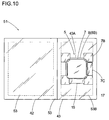
- Reference number 40 denotes a container, and the container 40 comprises a temperature controlling unit 41, a main lid 42 and the insulating container 3.
- the temperature controlling unit 41 comprises a sub-lid 43 formed with a through-hole 43A on a substantial center thereof, and the temperature controlling subunit 5.
- the sub-lid 43 is made of an insulative foam synthetic resin in a tabular shape, in a single-piece manner, and its entire surface is covered with an infrared reflection film as an infrared reflection layer.
- the sub-lid 43 is so formed as to have a size partially closing and sealing the opening 3F of the insulating container 3.
- a step member 43B is formed on the through-hole 43A, and the step member 8B, formed on the outer circumference of the base 8 of the temperature controlling subunit 5 in association with the step member 43B, so contacts the step member 43B as to allow the base 8 to fit into the through-hole 43A, whereby the base 8 of the temperature controlling subunit 5 is placed on the sub-lid 43.
- the main lid 42 is made of an insulative foam synthetic resin in a tabular shape, in a single-piece manner, and its entire surface is covered with an infrared reflection film as an infrared reflection layer.
- the main lid 42 is openably and closably attached to the opening 3F in such a manner as to close and seal the remaining portion of the opening 3F not closed and sealed by the temperature controlling unit 41.
- the temperature controlling subunit 5 is assembled.
- the assembling of the temperature controlling subunit 5 is the same as that of the first embodiment.
- the assembled temperature controlling subunit 5 is attached to the through-hole 43A formed in the sub-lid 43. That is, the base 8 is fitted in and engaged with the through-hole 43A in such a manner as to allow the step member 8B formed on the base 8 of the temperature controlling subunit 5 to mount on the step 43B of the through-hole 43A, whereby the temperature controlling subunit 5 is attached to the sub-lid 43.
- the heat absorbing sink 9 since the heat absorbing sink 9 is formed to have the size not to protrude from the outer circumference of the lower portion of the base 8, the heat absorbing sink 9 does not interfere with the through-hole 43A when the temperature controlling subunit 5 is attached to the sub-lid 43.
- the temperature controlling unit 41 is structured by attaching the temperature controlling subunit 5 to the sub-lid 43 thus way, it is possible to obtain the temperature controlling units 41 of various sizes, that is, the temperature controlling units 41 that can match the insulating containers 3 and the main lids 42 of various sizes, by using the common temperature controlling subunit 5 and changing the sub-lid 43 only.
- the sub-lid 43 is covered with an infrared reflection film, but basically made of an insulative foam synthetic resin in a tabular shape, in a single-piece manner, and thus the sub-lids 43 of various sizes can be easily and inexpensively obtained. Accordingly, it is possible to manufacture the temperature controlling unit 41 inexpensively.
- the temperature controlling unit 41 is so attached to the opening 3F of the insulating container 3 as to partially close and seal the opening 3F, and the main lid 42 is so attached to the remaining portion of the opening 3F which is not closed and sealed by the temperature controlling unit 41.
- the temperature controlling unit 41 is so attached as to allow the heat absorbing sink 9 and the fan 14 to be the interior of the insulating container 3.
- the operation of the temperature controlling subunit 5 is the same as those of the first embodiment, and thus explanations thereof will be omitted at here.
- the insulating container 3 and the main lid 42 are made of a light foam synthetic resin in a tabular shape and an infrared reflection film, they have extremely light-weight structure, and the temperature controlling unit 41 also has a relatively light-weight structure as including the sub-lid 43 made of a foam synthetic resin in a tabular shape and an infrared reflection film, and the temperature controlling subunit 5 using the relatively light Stirling refrigerator 6. Accordingly, the container 40 using the temperature controlling unit 41 as a whole can have a relatively light-weight structure.
- the sub-lid 43 and the insulating container 3 are covered with infrared reflection films, it is possible to prevent infrared, that is, heat from entering into the interior of the container 40 from the outside thereof, the interior of the container 40 can be not only efficiently cooled, but also cooled to a very low temperature. Further, as the temperature controlling unit 41 and the main lid 42 are individually provided, the opening 3F of the insulating container 3 included in the container 40 can be easily opened and items to be stored can be easily put into and taken out from the container 40 with the temperature controlling unit 41 attached to the opening 3F and the light main lid 42 opened.
- the fourth embodiment is made of a foam synthetic resin in a tabular shape, in a single-piece manner, the sub-lid 43 and further the entire temperature controlling unit 41 can be light and inexpensive. Moreover, the sub-lid 43 can be easily structured in an arbitrary size.
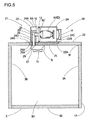
- Reference number 50 denotes a container, and the container 50 comprises a temperature controlling unit 51 and an insulating container 3.
- the temperature controlling unit 51 comprises a frame 53 which is formed in such a shape that two quadrangles with same widths are arranged as to have respective one edges to come in contact with each other, thereby having the common edge, the main lid 42 openably and closably attached to a first opening 53A as the opening of the frame 53, the sub-lid 43 attached to a second opening 53B, as the opening of the frame 53, and formed with the through-hole 43A on the substantial center thereof, and the temperature controlling subunit 5 to be attached to the through-hole 43A.
- the frame 53 is so formed that the first opening 53A is larger than the second opening 53B.
- the frame 53 is made of a material having small heat conductivity like a synthetic resin, and desirably, engineering plastic of high-strength.
- the main lid 42 and the sub-lid 43 have the same structures as the fourth embodiment.
- foam synthetic resin of the main lid 42 and the sub-lid 43 foam polyurethane, foam polystyrene, etc. can be used.
- one edge of the main lid 42 is freely movably fixed to the frame 53, thereby openably and closably closing and sealing the first opening 53A.
- the sub-lid 43 has, as same as the fourth embodiment, the through-hole 43A formed with the step member 43B for placing the base 8 of the temperature controlling subunit 5.
- the temperature controlling subunit 5 has the same structure as the first embodiment.
- the insulating container 3 has the right wall 3A, the left wall 3B, the front wall 3C, the rear wall 3D, the bottom wall 3E and the lid 16 for the insulating container 3 as the second lid, and it has a foldable structure.
- Each of the walls 3A, 3B, 3C, 3D, and 3E, and the lid 16 is made of an insulative foam synthetic resin in a tabular shape, in a single-piece manner, and each of the entire surfaces is covered with an infrared reflection film as an infrared reflection layer.
- the cover 17 is as same as that of the first embodiment.
- the edge of the lid 16 is freely movably attached to the upper end of the cover 17. As the insulating container 3 is foldable, it can save space by folding the walls 3A, 3B, 3C, 3D, 3E and the lid 16 when unused.
- the temperature controlling subunit 5 is assembled and attached to the sub-lid 43.
- the heat absorbing sink 9 does not interfere with the through-hole 43A when the temperature controlling subunit 5 is attached to the sub-lid 43.
- the main lid 42 and the sub-lid 43 with the temperature controlling subunit 5, attached thereto thus way, are attached to the first opening 53A and the second opening 53B, respectively.
- the sub-lid 43 is fixed to the second opening 53B of the frame 53, while the main lid 42 is so attached to the first opening 53A as to allow the one edge thereof to be freely movable for the frame 53. That is, the main lid 42 freely movably attached to the frame 53 openably and closably closes and seals the first opening 53A.
- the temperature controlling unit 51 is structured by attaching the main lid 42 and the sub-lid 43 with the temperature controlling subunit 5 attached thereto, to the frame 53, the same effectiveness as those of the aforementioned embodiments can be obtained by using the common temperature controlling subunit 5 and changing the frame 53, the main lid 42 and the sub-lid 43.
- the main lid 42 and the sub-lid 43 are also covered with an infrared reflection film in this embodiment, but each basically made of an insulative foam synthetic resin in a tabular shape, in a single-piece manner, and thus they can obtain the same effectiveness as those of the aforementioned embodiments.
- the operation of the fifth embodiment will now be explained.
- items which were refrigerated or frozen beforehand by a refrigerator or a freezer is taken in the insulating container 3, and the temperature controlling unit 51 is so attached to the upper end of the insulating container 3 as to close and seal the opening of the insulating container 3.
- the temperature controlling unit 51 is so attached as to allow the frame 53 to contact the upper end of the insulating container 3, that is, as to allow the heat absorbing sink 9 and the fan 14 to be the interior of the insulating container 3.
- the operation of the temperature controlling subunit 5, the main lid 42, the sub-lid 43 and the insulating container 53 are the same as the aforementioned embodiment.
- the frame 53 is made of a low heat-conductive material, it is possible to prevent infrared, that is, heat from entering into the interior of the container 50 from the outside thereof via the frame 53.
- infrared that is, heat from entering into the interior of the container 50 from the outside thereof via the frame 53.
- the container 50 is unused, it can save space by detaching the temperature controlling unit 51 and folding the insulating container 52 as explained above.
- the same effectiveness as those of the aforementioned embodiments can be obtained by the fifth embodiment.
- the frame 53 is made of a synthetic resin or the like as a low heat-conductive material, it is possible to prevent heat from entering into the interior of the container 50 from the outside thereof, and thus the temperature of the interior thereof can be efficiently controlled.
- the present invention is not limited to the aforementioned embodiments, and can be modified within the scope of the present invention.
- a thermo module utilizing the Peltier effect may be used as illustrated in FIG. 12, or a heater may be used as illustrated in FIG. 13.
- the temperature controlling subunit is exposed from the lid, the sub-lid or the insulating container, but it may be so structured as to be accommodated by the lid, the sub-lid or the insulating container.
- the second lid is attached to the insulating container, but it may be an independent lid from the insulating container.
- the main lid is freely movably attached to the frame in the fifth embodiment, but as long as it opens or closes the opening of the frame, it may be freely movably attached to, for instance, the sub-lid.
- the frame is formed with two openings in the fifth embodiment, but it may be formed with one opening and both the main lid and the sub-lid may cover this opening.
- the frame may be formed with more than or equal to three openings, the sub-lid may cover one of the openings, and the other openings may be opened or closed by several main lids.
- the main lid, the sub-lid and the insulating container are made of foam synthetic resins, but other insulating materials, for instance, a vacuum insulation panel or the like may be used.
- a vacuum insulation panel or the like may be used.
- insulation characteristics thereof are improved, thus preventing heat from entering the interior of the container from the outside thereof, whereby the interior of the container can be cooled to further cold temperature and rapidly.
Landscapes
- Engineering & Computer Science (AREA)
- Physics & Mathematics (AREA)
- Mechanical Engineering (AREA)
- Thermal Sciences (AREA)
- General Engineering & Computer Science (AREA)
- Chemical & Material Sciences (AREA)
- Combustion & Propulsion (AREA)
- Devices That Are Associated With Refrigeration Equipment (AREA)
Applications Claiming Priority (2)
| Application Number | Priority Date | Filing Date | Title |
|---|---|---|---|
| JP2004242952A JP4235151B2 (ja) | 2004-08-23 | 2004-08-23 | 貯蔵庫 |
| JP2004278464A JP2006090665A (ja) | 2004-09-24 | 2004-09-24 | 冷却ユニット及びこの冷却ユニットを用いた保冷庫 |
Publications (2)
| Publication Number | Publication Date |
|---|---|
| EP1630492A2 true EP1630492A2 (de) | 2006-03-01 |
| EP1630492A3 EP1630492A3 (de) | 2008-10-29 |
Family
ID=35457463
Family Applications (1)
| Application Number | Title | Priority Date | Filing Date |
|---|---|---|---|
| EP05015587A Withdrawn EP1630492A3 (de) | 2004-08-23 | 2005-07-19 | Temperaturregeleinheit und dieser benutzender Behälter |
Country Status (2)
| Country | Link |
|---|---|
| US (1) | US20060037327A1 (de) |
| EP (1) | EP1630492A3 (de) |
Cited By (2)
| Publication number | Priority date | Publication date | Assignee | Title |
|---|---|---|---|---|
| DE102009023978A1 (de) | 2009-06-05 | 2010-12-09 | Danfoss Compressors Gmbh | Stirling-Kühleinrichtung |
| DE102009023970A1 (de) | 2009-06-05 | 2011-06-16 | Danfoss Flensburg Gmbh | Stirling-Kühleinrichtung |
Families Citing this family (3)
| Publication number | Priority date | Publication date | Assignee | Title |
|---|---|---|---|---|
| US8559101B2 (en) * | 2005-08-26 | 2013-10-15 | Panasonic Corporation | Reflector and apparatus including the reflector |
| CN106880244B (zh) * | 2017-03-23 | 2018-02-23 | 佳木斯大学 | 一种医用保温杯及使用方法 |
| CN108224834A (zh) * | 2017-12-26 | 2018-06-29 | 宁波华斯特林电机制造有限公司 | 一种制冷模块以及使用该制冷模块的制冷设备 |
Citations (3)
| Publication number | Priority date | Publication date | Assignee | Title |
|---|---|---|---|---|
| JPH0253022U (de) | 1988-10-11 | 1990-04-17 | ||
| JP2000304402A (ja) | 1999-04-23 | 2000-11-02 | Twinbird Corp | 電子式温冷蔵庫 |
| JP2001311576A (ja) | 2000-04-27 | 2001-11-09 | Sharp Corp | 保冷庫 |
Family Cites Families (15)
| Publication number | Priority date | Publication date | Assignee | Title |
|---|---|---|---|---|
| NL148795C (de) * | 1964-07-24 | |||
| US4723418A (en) * | 1987-04-27 | 1988-02-09 | Whitmer Ii Robert L | Self-contained portable refrigeration unit |
| EP0366818A1 (de) * | 1988-11-02 | 1990-05-09 | Leybold Aktiengesellschaft | Kryostat mit einem Flüssig-Stickstoff (LN2)-Bad |
| JPH0726784B2 (ja) * | 1992-09-25 | 1995-03-29 | 岩谷産業株式会社 | 簡易液体窒素製造装置 |
| JP2001082852A (ja) * | 1999-09-09 | 2001-03-30 | Sharp Corp | 解凍室付冷蔵庫 |
| US6266963B1 (en) * | 1999-10-05 | 2001-07-31 | The Coca-Cola Company | Apparatus using stirling cooler system and methods of use |
| WO2001084065A1 (en) * | 2000-04-27 | 2001-11-08 | Sharp Kabushiki Kaisha | Cold insulating chamber |
| JP2002062033A (ja) * | 2000-08-11 | 2002-02-28 | Fujitsu General Ltd | 組立式冷温蔵庫 |
| JP2002090022A (ja) * | 2000-09-14 | 2002-03-27 | Sharp Corp | 携帯用冷温蔵庫 |
| US6550255B2 (en) * | 2001-03-21 | 2003-04-22 | The Coca-Cola Company | Stirling refrigeration system with a thermosiphon heat exchanger |
| US6581389B2 (en) * | 2001-03-21 | 2003-06-24 | The Coca-Cola Company | Merchandiser using slide-out stirling refrigeration deck |
| JP3930312B2 (ja) * | 2001-12-17 | 2007-06-13 | 松下冷機株式会社 | 熱電装置とこの装置を備えた貯蔵庫とこの貯蔵庫の組み立て方法 |
| US6751963B2 (en) * | 2002-09-24 | 2004-06-22 | The Coleman Company, Inc. | Portable insulated container with refrigeration |
| JP2004176952A (ja) * | 2002-11-25 | 2004-06-24 | Twinbird Corp | 冷却庫 |
| JP2004225942A (ja) * | 2003-01-20 | 2004-08-12 | Twinbird Corp | 低温収納庫 |
-
2005
- 2005-07-19 EP EP05015587A patent/EP1630492A3/de not_active Withdrawn
- 2005-07-20 US US11/185,050 patent/US20060037327A1/en not_active Abandoned
Patent Citations (3)
| Publication number | Priority date | Publication date | Assignee | Title |
|---|---|---|---|---|
| JPH0253022U (de) | 1988-10-11 | 1990-04-17 | ||
| JP2000304402A (ja) | 1999-04-23 | 2000-11-02 | Twinbird Corp | 電子式温冷蔵庫 |
| JP2001311576A (ja) | 2000-04-27 | 2001-11-09 | Sharp Corp | 保冷庫 |
Cited By (2)
| Publication number | Priority date | Publication date | Assignee | Title |
|---|---|---|---|---|
| DE102009023978A1 (de) | 2009-06-05 | 2010-12-09 | Danfoss Compressors Gmbh | Stirling-Kühleinrichtung |
| DE102009023970A1 (de) | 2009-06-05 | 2011-06-16 | Danfoss Flensburg Gmbh | Stirling-Kühleinrichtung |
Also Published As
| Publication number | Publication date |
|---|---|
| US20060037327A1 (en) | 2006-02-23 |
| EP1630492A3 (de) | 2008-10-29 |
Similar Documents
| Publication | Publication Date | Title |
|---|---|---|
| US20090200320A1 (en) | Storage container | |
| US6751963B2 (en) | Portable insulated container with refrigeration | |
| US5605047A (en) | Enclosure for thermoelectric refrigerator and method | |
| WO2018233611A1 (zh) | 一种便携式制冷盒 | |
| JP4903831B2 (ja) | 配送用保冷容器 | |
| EP1630492A2 (de) | Temperaturregeleinheit und dieser benutzender Behälter | |
| US3018638A (en) | Portable refrigeration apparatus | |
| JPH0771890B2 (ja) | 自動車のグラブコンパートメントを冷却する装置 | |
| JP2007045519A (ja) | 保冷ボックス、蓄冷材等の組合せによる要冷品の温度管理方法 | |
| JP2020176790A (ja) | 保冷ボックスおよび食品配送用バイク | |
| JP2007240021A (ja) | 折畳み式保冷庫 | |
| WO2018101144A1 (ja) | 保温又は保冷庫 | |
| JP4235151B2 (ja) | 貯蔵庫 | |
| JPH09280718A (ja) | 冷却貯蔵庫 | |
| JP2006090665A (ja) | 冷却ユニット及びこの冷却ユニットを用いた保冷庫 | |
| JPH08296941A (ja) | 携帯用電子加熱冷却容器 | |
| JP3321798B2 (ja) | 電子式冷蔵庫 | |
| CN221444562U (zh) | 一种柔性分体式冰箱 | |
| JPH1068570A (ja) | 電子冷温蔵庫 | |
| CN223015402U (zh) | 存储箱 | |
| JP2007271091A (ja) | 保冷箱 | |
| JP2001321071A (ja) | 低温漬物器 | |
| JP2006118834A (ja) | 冷却ユニット及びこの冷却ユニットを用いた保冷庫 | |
| JP2002017583A (ja) | 穀物保冷装置 | |
| JPH1078280A (ja) | 化粧品等の携帯用クーラボックスの冷却装置 |
Legal Events
| Date | Code | Title | Description |
|---|---|---|---|
| PUAI | Public reference made under article 153(3) epc to a published international application that has entered the european phase |
Free format text: ORIGINAL CODE: 0009012 |
|
| AK | Designated contracting states |
Kind code of ref document: A2 Designated state(s): AT BE BG CH CY CZ DE DK EE ES FI FR GB GR HU IE IS IT LI LT LU LV MC NL PL PT RO SE SI SK TR |
|
| AX | Request for extension of the european patent |
Extension state: AL BA HR MK YU |
|
| PUAL | Search report despatched |
Free format text: ORIGINAL CODE: 0009013 |
|
| AK | Designated contracting states |
Kind code of ref document: A3 Designated state(s): AT BE BG CH CY CZ DE DK EE ES FI FR GB GR HU IE IS IT LI LT LU LV MC NL PL PT RO SE SI SK TR |
|
| AX | Request for extension of the european patent |
Extension state: AL BA HR MK YU |
|
| 17P | Request for examination filed |
Effective date: 20090427 |
|
| 17Q | First examination report despatched |
Effective date: 20090604 |
|
| AKX | Designation fees paid |
Designated state(s): DE FR GB IT |
|
| STAA | Information on the status of an ep patent application or granted ep patent |
Free format text: STATUS: THE APPLICATION IS DEEMED TO BE WITHDRAWN |
|
| 18D | Application deemed to be withdrawn |
Effective date: 20111025 |