EP1630496A2 - Système de refroidissement - Google Patents
Système de refroidissement Download PDFInfo
- Publication number
- EP1630496A2 EP1630496A2 EP05255234A EP05255234A EP1630496A2 EP 1630496 A2 EP1630496 A2 EP 1630496A2 EP 05255234 A EP05255234 A EP 05255234A EP 05255234 A EP05255234 A EP 05255234A EP 1630496 A2 EP1630496 A2 EP 1630496A2
- Authority
- EP
- European Patent Office
- Prior art keywords
- refrigerant
- evaporator
- expansion
- cooling system
- evaporators
- Prior art date
- Legal status (The legal status is an assumption and is not a legal conclusion. Google has not performed a legal analysis and makes no representation as to the accuracy of the status listed.)
- Withdrawn
Links
Images


Classifications
-
- F—MECHANICAL ENGINEERING; LIGHTING; HEATING; WEAPONS; BLASTING
- F25—REFRIGERATION OR COOLING; COMBINED HEATING AND REFRIGERATION SYSTEMS; HEAT PUMP SYSTEMS; MANUFACTURE OR STORAGE OF ICE; LIQUEFACTION SOLIDIFICATION OF GASES
- F25B—REFRIGERATION MACHINES, PLANTS OR SYSTEMS; COMBINED HEATING AND REFRIGERATION SYSTEMS; HEAT PUMP SYSTEMS
- F25B39/00—Evaporators; Condensers
- F25B39/02—Evaporators
- F25B39/022—Evaporators with plate-like or laminated elements
-
- F—MECHANICAL ENGINEERING; LIGHTING; HEATING; WEAPONS; BLASTING
- F25—REFRIGERATION OR COOLING; COMBINED HEATING AND REFRIGERATION SYSTEMS; HEAT PUMP SYSTEMS; MANUFACTURE OR STORAGE OF ICE; LIQUEFACTION SOLIDIFICATION OF GASES
- F25B—REFRIGERATION MACHINES, PLANTS OR SYSTEMS; COMBINED HEATING AND REFRIGERATION SYSTEMS; HEAT PUMP SYSTEMS
- F25B47/00—Arrangements for preventing or removing deposits or corrosion, not provided for in another subclass
- F25B47/02—Defrosting cycles
-
- F—MECHANICAL ENGINEERING; LIGHTING; HEATING; WEAPONS; BLASTING
- F25—REFRIGERATION OR COOLING; COMBINED HEATING AND REFRIGERATION SYSTEMS; HEAT PUMP SYSTEMS; MANUFACTURE OR STORAGE OF ICE; LIQUEFACTION SOLIDIFICATION OF GASES
- F25D—REFRIGERATORS; COLD ROOMS; ICE-BOXES; COOLING OR FREEZING APPARATUS NOT OTHERWISE PROVIDED FOR
- F25D21/00—Defrosting; Preventing frosting; Removing condensed or defrost water
- F25D21/06—Removing frost
-
- F—MECHANICAL ENGINEERING; LIGHTING; HEATING; WEAPONS; BLASTING
- F25—REFRIGERATION OR COOLING; COMBINED HEATING AND REFRIGERATION SYSTEMS; HEAT PUMP SYSTEMS; MANUFACTURE OR STORAGE OF ICE; LIQUEFACTION SOLIDIFICATION OF GASES
- F25B—REFRIGERATION MACHINES, PLANTS OR SYSTEMS; COMBINED HEATING AND REFRIGERATION SYSTEMS; HEAT PUMP SYSTEMS
- F25B2347/00—Details for preventing or removing deposits or corrosion
- F25B2347/02—Details of defrosting cycles
- F25B2347/021—Alternate defrosting
-
- F—MECHANICAL ENGINEERING; LIGHTING; HEATING; WEAPONS; BLASTING
- F25—REFRIGERATION OR COOLING; COMBINED HEATING AND REFRIGERATION SYSTEMS; HEAT PUMP SYSTEMS; MANUFACTURE OR STORAGE OF ICE; LIQUEFACTION SOLIDIFICATION OF GASES
- F25B—REFRIGERATION MACHINES, PLANTS OR SYSTEMS; COMBINED HEATING AND REFRIGERATION SYSTEMS; HEAT PUMP SYSTEMS
- F25B2400/00—Component parts or details not otherwise provided for in this subclass
- F25B2400/05—Compression system with heat exchange between particular parts of the system
- F25B2400/052—Compression system with heat exchange between particular parts of the system between the capillary tube and another part of the refrigeration cycle
-
- F—MECHANICAL ENGINEERING; LIGHTING; HEATING; WEAPONS; BLASTING
- F25—REFRIGERATION OR COOLING; COMBINED HEATING AND REFRIGERATION SYSTEMS; HEAT PUMP SYSTEMS; MANUFACTURE OR STORAGE OF ICE; LIQUEFACTION SOLIDIFICATION OF GASES
- F25B—REFRIGERATION MACHINES, PLANTS OR SYSTEMS; COMBINED HEATING AND REFRIGERATION SYSTEMS; HEAT PUMP SYSTEMS
- F25B2500/00—Problems to be solved
- F25B2500/18—Optimization, e.g. high integration of refrigeration components
-
- F—MECHANICAL ENGINEERING; LIGHTING; HEATING; WEAPONS; BLASTING
- F25—REFRIGERATION OR COOLING; COMBINED HEATING AND REFRIGERATION SYSTEMS; HEAT PUMP SYSTEMS; MANUFACTURE OR STORAGE OF ICE; LIQUEFACTION SOLIDIFICATION OF GASES
- F25B—REFRIGERATION MACHINES, PLANTS OR SYSTEMS; COMBINED HEATING AND REFRIGERATION SYSTEMS; HEAT PUMP SYSTEMS
- F25B2600/00—Control issues
- F25B2600/25—Control of valves
- F25B2600/2511—Evaporator distribution valves
Definitions
- the present invention relates to a cooling system, and more particularly, to a cooling system efficiently defrosting an evaporator without an extra defrosting heater.
- a cooling system (or a cooling cycle) includes a closed circuit having a compressor, a condenser, an evaporator and related devices.
- a refrigerant compressed in the compressor is condensed into a liquid by the condenser, and then evaporated in the evaporator.
- the evaporator generates cool air in the process of evaporating the refrigerant by using latent heat around the evaporator.
- a defrosting unit is generally placed in the cooling system to defrost the evaporator.
- defrosting unit includes: a defrosting heater at a lower part of an evaporator; a hot pipe between a compressor and a condenser; a defrosting pipe branched from the hot pipe, passing by the evaporator and connected to an entrance of the evaporator; and a control valve controlling a path of a refrigerant at a branching point of the hot pipe and the defrosting pipe.
- An aspect of the present invention provides a cooling system efficiently defrosting an evaporator without an extra defrosting heater, thereby having an improved cooling efficiency and decreased power consumption.
- a cooling system including a compressor compressing a refrigerant and a condenser condensing the compressed refrigerant.
- the cooling system includes: an evaporator section having a plurality of evaporators evaporating the refrigerant condensed in the condenser; a switching valve on a refrigerant line between the condenser and the evaporator, and selectively switching a refrigerant supply to the plurality of evaporators; and a refrigerant expansion part adjacent to at least one of the evaporators, allowing refrigerant introduced into the plurality of evaporators through the switching valve to expand.
- a refrigerant inlet of the refrigerant expansion part adjacent to any of the evaporators is connected to the switching valve, and a refrigerant outlet thereof is connected to an inlet of another evaporator.
- each of the evaporating parts may include a refrigerant pipe and a plurality of fins provided transversely to the lengthwise direction of the refrigerant pipe, and the refrigerant expansion part is provided along each of the refrigerant pipes.
- each of the evaporating parts may include a refrigerant pipe and a plurality of fins provided transversely to the lengthwise direction of the refrigerant pipe, and the refrigerant expansion part is provided in parallel with each of the refrigerant pipes.
- the refrigerant expansion part may be a capillary tube.
- the switching valve may include a solenoid valve.
- a cooling system including a compressor compressing a refrigerant and a condenser condensing the compressed refrigerant.
- the cooling system includes: an evaporator having a first evaporating part and a second evaporating part evaporating the condensed refrigerant; a switching valve on a refrigerant line between the condenser and the evaporator, and selectively supplying refrigerant to the first evaporating part and the second evaporating part; a first refrigerant expansion part in at least a portion of the second evaporating part, and allowing the refrigerant introduced into the first evaporating part through the switching valve to expand; and a second refrigerant expansion part provided in at least a portion of the first evaporating part, and allowing the refrigerant introduced into the second evaporating part through the switching valve to expand.
- a first circulation in which the condensed refrigerant is supplied to the first evaporating part through the first refrigerant expansion part, and a second circulation in which the refrigerant from the condenser is introduced into the second evaporating part through the second refrigerant expansion part, are selectively provided.
- the second evaporating part is defrosted during the first circulation by heat from the first refrigerant expansion part, and the first evaporating part is defrosted during the second circulation by heat from the second refrigerant expansion part.
- the first evaporating part and the second evaporating part may respectively include a refrigerant pipe and a plurality of fins arranged transversely to the lengthwise direction of the refrigerant pipe, and the first and second refrigerant expansion parts may be respectively provided along a surface of the refrigerant pipe of the first and second evaporating parts.
- the switching valve may include a solenoid valve.
- a cooling system including: a first loop including a first refrigerant expansion section allowing compressed refrigerant flowing therethrough to expand and a first evaporator downstream of the first refrigerant expansion section; and a second loop including a second refrigerant expansion section allowing compressed refrigerant flowing therethrough to expand and a second evaporator downstream of the second refrigerant expansion section.
- first loop including a first refrigerant expansion section allowing compressed refrigerant flowing therethrough to expand and a first evaporator downstream of the first refrigerant expansion section
- a second loop including a second refrigerant expansion section allowing compressed refrigerant flowing therethrough to expand and a second evaporator downstream of the second refrigerant expansion section.
- a method of preventing frost on evaporators of a cooling system including: supplying compressed refrigerant to a first expansion section allowing the compressed refrigerant to expand and heat the first expansion section and then to a first evaporator downstream of the first expansion section; and supplying compressed refrigerant to a second expansion section allowing the compressed refrigerant to expand and heat the second expansion section and then to a second evaporator downstream of the second expansion section.
- the first expansion section is proximate to the second evaporator and the second expansion section is proximate to the first evaporator.
- a cooling system includes a compressor 10 compressing a refrigerant to a high temperature and a high pressure; a condenser 60 condensing the compressed refrigerant into a liquid; and respective first and second evaporators 51, 52 evaporating the condensed refrigerant.
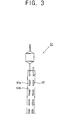
- the first evaporator 51 includes a refrigerant pipe 51a through which the refrigerant flows and a plurality of plate-shaped fins 51b arranged in parallel at specified intervals to be crossed with the refrigerant pipe 51a.
- a first capillary tube 41 On a refrigerant line connecting the switching valve 30 and the first evaporator 51 is a first capillary tube 41 as a first refrigerant expansion part decompressing the high-pressure refrigerant from the condenser 60.
Landscapes
- Engineering & Computer Science (AREA)
- Physics & Mathematics (AREA)
- Mechanical Engineering (AREA)
- Thermal Sciences (AREA)
- General Engineering & Computer Science (AREA)
- Chemical & Material Sciences (AREA)
- Combustion & Propulsion (AREA)
- Defrosting Systems (AREA)
- Compression-Type Refrigeration Machines With Reversible Cycles (AREA)
Applications Claiming Priority (1)
| Application Number | Priority Date | Filing Date | Title |
|---|---|---|---|
| KR1020040068118A KR100597748B1 (ko) | 2004-08-27 | 2004-08-27 | 냉동시스템 |
Publications (2)
| Publication Number | Publication Date |
|---|---|
| EP1630496A2 true EP1630496A2 (fr) | 2006-03-01 |
| EP1630496A3 EP1630496A3 (fr) | 2007-08-29 |
Family
ID=35414552
Family Applications (1)
| Application Number | Title | Priority Date | Filing Date |
|---|---|---|---|
| EP05255234A Withdrawn EP1630496A3 (fr) | 2004-08-27 | 2005-08-25 | Système de refroidissement |
Country Status (3)
| Country | Link |
|---|---|
| US (1) | US20060042310A1 (fr) |
| EP (1) | EP1630496A3 (fr) |
| KR (1) | KR100597748B1 (fr) |
Cited By (3)
| Publication number | Priority date | Publication date | Assignee | Title |
|---|---|---|---|---|
| CN109442836A (zh) * | 2018-10-23 | 2019-03-08 | 海信(山东)冰箱有限公司 | 一种冷柜及其控制方法 |
| DE102015120138B4 (de) | 2014-11-27 | 2021-10-21 | Espec Corp. | Umgebungs-Testvorrichtung, Kühleinrichtung und Umgebungs-Testverfahren |
| CN115264793A (zh) * | 2022-06-17 | 2022-11-01 | 青岛海尔空调器有限总公司 | 用于控制空调节能的方法、装置、空调和存储介质 |
Families Citing this family (5)
| Publication number | Priority date | Publication date | Assignee | Title |
|---|---|---|---|---|
| KR101345666B1 (ko) * | 2007-05-25 | 2013-12-30 | 엘지전자 주식회사 | 냉장고 |
| US8794026B2 (en) | 2008-04-18 | 2014-08-05 | Whirlpool Corporation | Secondary cooling apparatus and method for a refrigerator |
| KR101542171B1 (ko) * | 2013-10-29 | 2015-08-06 | 한국에너지기술연구원 | 히트펌프 시스템 |
| US12366390B2 (en) * | 2020-05-29 | 2025-07-22 | The Coca-Cola Company | Double skin heat exchanger apparatus and system |
| CN115540405A (zh) * | 2021-06-29 | 2022-12-30 | 青岛海尔电冰箱有限公司 | 用于冷藏冷冻装置的制冷系统以及冷藏冷冻装置 |
Family Cites Families (15)
| Publication number | Priority date | Publication date | Assignee | Title |
|---|---|---|---|---|
| US2708348A (en) * | 1951-11-02 | 1955-05-17 | Nash Kelvinator Corp | Defrosting means for refrigerating apparatus |
| US3218819A (en) * | 1963-05-16 | 1965-11-23 | Revco Inc | Refrigeration apparatus |
| US4122687A (en) * | 1976-12-09 | 1978-10-31 | Mckee Thomas M | Refrigeration system with low energy defrost |
| GB2143014B (en) * | 1983-05-16 | 1986-09-17 | Hotpoint Ltd | Refrigerator/freezer units |
| US5241838A (en) * | 1991-12-26 | 1993-09-07 | General Electric Company | Refrigerator with spine fin evaporator |
| US5551250A (en) * | 1994-09-08 | 1996-09-03 | Traulsen & Co. Inc. | Freezer evaporator defrost system |
| JP3177428B2 (ja) * | 1995-10-11 | 2001-06-18 | 三洋電機株式会社 | 低温ショーケース |
| US5901570A (en) * | 1997-06-30 | 1999-05-11 | Daewoo Electronics Co., Ltd. | Refrigerator having a refrigeration system |
| US20010035016A1 (en) * | 1997-12-09 | 2001-11-01 | Weber Paul R. | Compressor control mechanism and method |
| NO20005575D0 (no) * | 2000-09-01 | 2000-11-03 | Sinvent As | Metode og arrangement for avriming av kulde-/varmepumpeanlegg |
| ES2266001T3 (es) * | 2000-11-03 | 2007-03-01 | Arcelik A.S. | Un metodo de descongelacion y un aparato de refrigeracion que usa el mismo. |
| JP3576092B2 (ja) * | 2000-11-10 | 2004-10-13 | 松下冷機株式会社 | 冷蔵庫 |
| JP3956674B2 (ja) * | 2001-11-13 | 2007-08-08 | ダイキン工業株式会社 | 冷媒回路 |
| TWI301188B (en) * | 2002-08-30 | 2008-09-21 | Sanyo Electric Co | Refrigeant cycling device and compressor using the same |
| US7210303B2 (en) * | 2003-12-04 | 2007-05-01 | Carrier Corporation | Transcritical heat pump water heating system using auxiliary electric heater |
-
2004
- 2004-08-27 KR KR1020040068118A patent/KR100597748B1/ko not_active Expired - Fee Related
-
2005
- 2005-08-25 EP EP05255234A patent/EP1630496A3/fr not_active Withdrawn
- 2005-08-26 US US11/211,479 patent/US20060042310A1/en not_active Abandoned
Cited By (3)
| Publication number | Priority date | Publication date | Assignee | Title |
|---|---|---|---|---|
| DE102015120138B4 (de) | 2014-11-27 | 2021-10-21 | Espec Corp. | Umgebungs-Testvorrichtung, Kühleinrichtung und Umgebungs-Testverfahren |
| CN109442836A (zh) * | 2018-10-23 | 2019-03-08 | 海信(山东)冰箱有限公司 | 一种冷柜及其控制方法 |
| CN115264793A (zh) * | 2022-06-17 | 2022-11-01 | 青岛海尔空调器有限总公司 | 用于控制空调节能的方法、装置、空调和存储介质 |
Also Published As
| Publication number | Publication date |
|---|---|
| EP1630496A3 (fr) | 2007-08-29 |
| US20060042310A1 (en) | 2006-03-02 |
| KR20060019433A (ko) | 2006-03-03 |
| KR100597748B1 (ko) | 2006-07-07 |
Similar Documents
| Publication | Publication Date | Title |
|---|---|---|
| US8479527B2 (en) | Refrigerator and control method for the same | |
| KR101212698B1 (ko) | 히트 펌프식 급탕장치 | |
| CN111102770A (zh) | 连续制热的空调系统 | |
| CN109328287B (zh) | 制冷循环装置 | |
| US20110271703A1 (en) | Refrigerator | |
| KR101190492B1 (ko) | 히트펌프 연동 급탕장치 | |
| JP4269323B2 (ja) | ヒートポンプ給湯機 | |
| EP1347255A1 (fr) | Dégivrage d'un évaporateur de pompe à chaleur | |
| EP2354722A2 (fr) | Procédé de contrôle d'un système de réfrigération | |
| US7104084B2 (en) | Heat pump and structure of extraction heat exchanger thereof | |
| KR101401909B1 (ko) | 무착상 연속운전용 실외 열교환기가 형성된 히트펌프장치 및 제상방법 | |
| KR20190023010A (ko) | 핫가스 제상방식을 적용한 공기조화기 | |
| JP5404761B2 (ja) | 冷凍装置 | |
| EP1630496A2 (fr) | Système de refroidissement | |
| US11965683B2 (en) | Cooling system for low temperature storage | |
| WO2016046882A1 (fr) | Dispositif à cycle de réfrigération | |
| JP2009052880A (ja) | ヒートポンプ給湯機 | |
| KR100929192B1 (ko) | 공기 조화기 | |
| JP4428341B2 (ja) | 冷凍サイクル装置 | |
| KR101124872B1 (ko) | 복수 개의 증발부재를 구비한 히트펌프 | |
| KR102329452B1 (ko) | 냉장고 | |
| KR100558652B1 (ko) | 냉·난방기 | |
| EP3175184B1 (fr) | Appareil de réfrigération comportant un circuit de dégivrage d'évaporateur de compartiment congélation | |
| KR101164360B1 (ko) | 증기 분사 압축기를 포함하는 히트 펌프 장치 | |
| KR100794815B1 (ko) | 공기 조화 시스템 |
Legal Events
| Date | Code | Title | Description |
|---|---|---|---|
| PUAI | Public reference made under article 153(3) epc to a published international application that has entered the european phase |
Free format text: ORIGINAL CODE: 0009012 |
|
| 17P | Request for examination filed |
Effective date: 20050908 |
|
| AK | Designated contracting states |
Kind code of ref document: A2 Designated state(s): AT BE BG CH CY CZ DE DK EE ES FI FR GB GR HU IE IS IT LI LT LU LV MC NL PL PT RO SE SI SK TR |
|
| AX | Request for extension of the european patent |
Extension state: AL BA HR MK YU |
|
| PUAL | Search report despatched |
Free format text: ORIGINAL CODE: 0009013 |
|
| AK | Designated contracting states |
Kind code of ref document: A3 Designated state(s): AT BE BG CH CY CZ DE DK EE ES FI FR GB GR HU IE IS IT LI LT LU LV MC NL PL PT RO SE SI SK TR |
|
| AX | Request for extension of the european patent |
Extension state: AL BA HR MK YU |
|
| 17Q | First examination report despatched |
Effective date: 20071011 |
|
| AKX | Designation fees paid | ||
| REG | Reference to a national code |
Ref country code: DE Ref legal event code: 8566 |
|
| STAA | Information on the status of an ep patent application or granted ep patent |
Free format text: STATUS: THE APPLICATION IS DEEMED TO BE WITHDRAWN |
|
| 18D | Application deemed to be withdrawn |
Effective date: 20080222 |