EP1630980A2 - Procédé et dispositif de transmission de données par deux modes de transmission différents - Google Patents
Procédé et dispositif de transmission de données par deux modes de transmission différents Download PDFInfo
- Publication number
- EP1630980A2 EP1630980A2 EP05017359A EP05017359A EP1630980A2 EP 1630980 A2 EP1630980 A2 EP 1630980A2 EP 05017359 A EP05017359 A EP 05017359A EP 05017359 A EP05017359 A EP 05017359A EP 1630980 A2 EP1630980 A2 EP 1630980A2
- Authority
- EP
- European Patent Office
- Prior art keywords
- transmission
- data
- radio
- stationary
- mobile
- Prior art date
- Legal status (The legal status is an assumption and is not a legal conclusion. Google has not performed a legal analysis and makes no representation as to the accuracy of the status listed.)
- Granted
Links
Images



Classifications
-
- H—ELECTRICITY
- H04—ELECTRIC COMMUNICATION TECHNIQUE
- H04B—TRANSMISSION
- H04B7/00—Radio transmission systems, i.e. using radiation field
- H04B7/24—Radio transmission systems, i.e. using radiation field for communication between two or more posts
- H04B7/26—Radio transmission systems, i.e. using radiation field for communication between two or more posts at least one of which is mobile
- H04B7/2628—Radio transmission systems, i.e. using radiation field for communication between two or more posts at least one of which is mobile using code-division multiple access [CDMA] or spread spectrum multiple access [SSMA]
-
- H—ELECTRICITY
- H04—ELECTRIC COMMUNICATION TECHNIQUE
- H04Q—SELECTING
- H04Q2209/00—Arrangements in telecontrol or telemetry systems
- H04Q2209/60—Arrangements in telecontrol or telemetry systems for transmitting utility meters data, i.e. transmission of data from the reader of the utility meter
Definitions
- the invention relates to a method for transmitting data, in particular in the wireless remote reading of home consumption data or measured values by means of radio transmission, with data or radio telegrams, which are transmitted in at least two different transmission modes. Furthermore, an apparatus for carrying out the method is proposed.
- radio transmission a non-wired, per se non-collision-free transmission medium
- the invention can be used to particular advantage in non-wired transmission, it is also suitable for wired transmission systems. This applies in particular if, even in the case of wired transmission with regard to data density and transmission quality, the requirements described below with reference to a radio transmission system exist.
- stationary and mobile receivers are used.
- mobile reception is meant in the following systems in which the radio receiver is free to move. In such a system, the reader goes through a read area with a mobile receiver, receiving the readout Consumption data. These methods are suitable, for example, for a radio remote reading by "WALK-IN”, “WALK-BY” and “DRIVE-BY”.
- stationary reception refers to systems whose receivers are attached to a fixed location in the read area, at which they can receive the radio telegrams with the consumption data.
- Such a stationary receiver can for example be mounted in a freely accessible location in a building equipped with radio-enabled consumption recording devices so that a reading of all consumption data for the building can be made centrally at this stationary receiver, for example with downstream wired or wireless remote data transmission.
- Wireless metering systems that are read with a mobile receiver are particularly suitable for properties that are relatively infrequent, for example, once a year.
- Systems with stationary receivers can be used economically where frequent recording of consumption levels, for example once or twice a month, weekly or daily, is required.
- the transmitters for mobile reception should have the following characteristics: short range, high transmission frequency (at least in the reading period) and short radio telegrams or radio messages.
- the characteristics mentioned result from the high transmitter density in larger buildings, the desire for a quick reading in the case of an on-site inspection and the necessity to keep the intrinsic rate of collision of the radio telegrams on the transmission channel at a low level.
- the transmitters In order to ensure a speedy reading with a mobile receiver, the transmitters must transmit their radio telegrams (radio messages) very frequently.
- the magnitude of the transmission frequency is in the second to minute range.
- a stationary radio receiver can receive the data of the stations associated with it for days or hours, so that significantly longer transmission intervals are sufficient here and the radio channel as a whole is less loaded.
- acquisition devices that are rarely read out by mobile need to transmit more data in the individual radio telegrams than transmitters that are read at shorter intervals with stationary receivers.
- the transmitters it is therefore sufficient for the transmitters to transmit only those data which occur in the period between two transmission or reception times. If, for example, a temporal resolution of the consumption values in the half-monthly grid is required, a transmitter whose data is received and stored once a month by a stationary receiver must transmit only two values in a monthly varying radio message.
- a transmitter that is read only once a year with a mobile receiver must transmit twenty-four half-month values in one or more radio messages at the same time resolution at the time of reading.
- the system dynamics Due to reflections and partial cancellations of the signals, it is usually not possible to determine a receiver location for stationary reception in a building, which creates good reception conditions for all transmitters.
- a consumption meter with a radio transmitter for radio transmission of meter reading information to a mobile or stationary radio receiver is known in which the radio transmitter is prepared for transmitting radio telegrams of at least two different types of telegrams.
- the consumption counter works at times in a for the reception with stationary radio receiving devices optimized transmission mode and temporarily in a optimized for receiving with a mobile receiver transmission mode, in each case a different radio telegram type is used.
- the radio telegram types differ in the transmission power, the transmission frequency and / or the radio telegram length. In particular, it is important that the radio telegrams for stationary reception have a higher transmission power.
- the radio transmitter has a power amplifier output stage and a driver stage for the power amplifier output stage, wherein radio telegrams of the first radio telegram type for the mobile reception with non-activated power amplifier output stage only transmitted via the driver stage and radio telegrams of a second radio telegram type for stationary reception via the power amplifier output stage.
- the object of the invention is therefore to adapt the transmitter in the transmission of data in a simple and cost-effective manner to the requirements of transmission both with high data rates, eg. A mobile receiver, as well as high transmission quality, eg. For a stationary receiver.
- a first transmission mode uses a spread spectrum method according to the Codex principle and a second transmission mode uses a channel coding without code division.
- the transmitter is preferably designed so that the radio or data telegrams with the highest possible transmission step clock and the highest possible data rates (hereinafter also referred to as chip rates) are transmitted in order to make the radio or data telegrams as short as possible with existing data volume and to limit the number of collisions in a transmission channel as much as possible.
- the radio telegrams are made as redundant as possible using the bandwidth.
- a channel coding without code multiplex is used.
- exactly one bit data information can be used in exactly one step clock. It can in the data transmission but also DC-free or DC low-voltage coding methods are used in which the bit information is distributed to so many step clocks (chips) that a sum in the DC-free or low-signal is obtained.
- Known channel codings are, for example, data whitening, which represents a bitwise superimposition of the useful data stream with a pseudo-random binary stream having the same clock rate, or an efficient RLL coding, which has been described, for example, in DE 101 48 245 A1 of the Applicant.
- the number of step clocks used for the transmission of the data thus essentially corresponds to the number of data bits to be transmitted, with smaller differences in the number of step clocks and data bits used, in particular due to the requirement for DC freedom. Due to the efficient utilization of the step clocks for the transmission of data information, relatively short radio telegrams with large amounts of data can be transmitted. This allows a comparatively high transmission frequency, preferably in the reading period provided for reading, so that the efficient channel coding without code division fulfills the requirements for mobile reception.
- the technically identical transmitter for the preparation of the radio or data telegrams uses a spread spectrum method according to the code division multiplex principle, in which a data bit is sent as a specific, fixed predetermined sequence of several transmission step clocks (chips). It is also possible to combine a group of data bits for a specific sequence of chips.
- a data bit of a large number of transmission step clocks (chips) to be transmitted is assigned in a precisely defined chip sequence with changing signal values, for example signal values of +1 and -1 that change at a specific rhythm. This assignment is called spreading.
- the input signal is multiplied by an identical chip sequence as in the transmitter, and the resulting signal is integrated for despreading in order to obtain the original signal value.
- the receiving side despreading of the useful signal stochastically distributed, possibly existing interference signal are spread simultaneously, so that they make little sense in the signal level of the integrated signal.
- the energy of the interference signal is thus distributed to the full bandwidth, and correspondingly low is the interference component that falls within the bandwidth of the filter in the correlator of the receiver.
- the useful signal is correspondingly despread, so that its energy falls completely in the bandwidth of the filter in the correlator.
- This effect is based on the spread spectrum method typical process gain, which despite possible existing interference signals to a total sufficient reception leads even at lower radio or transmission quality, so that by the spread spectrum method according to the code division multiple higher range for the same Transmission power can be achieved. Therefore, this transmission mode for stationary reception is particularly suitable, especially since in stationary mode usually less data information must be transmitted and therefore the radio or data telegrams obtained by the spreading of a data bit is not excessively large length.
- the computational or theoretical process gain is 15 decibels (dB) by the application of the code division multiple, although the same transmitter, transmission power, and transmission frequency are used for both transmission modes.
- the same clock rates for mobile and stationary reception within the control unit of a consumption meter, work different, in particular all transmission modes with an identical transmission step clock (chip rate), wherein preferably the maximum transmission step clock is selected.
- the system is usually less expensive to implement, since the bandwidth of the baseband remains unchanged and simplifies the dimensioning of high-frequency circuit parts. Therefore, it is also particularly advantageous if the transmission modes, in particular the first transmission mode and the second transmission mode or all transmission modes, have the same carrier frequency, high-frequency carrier modulation and / or transmission power.
- the maximum utilization of a radio channel by a radio system is often determined by legal requirements, it is particularly advantageous if different or all transmission modes have a same time radio telegram length, which is predetermined by a certain number of transmission step clocks (chips). Since a different number of data information can be accommodated in a given number of chips in the various transmission modes, according to the invention the number of data information contained in the radio telegrams and to be transmitted is varied.
- a suitable compression method is described, for example, in the applicant's German patent 103 09 455, the content of which is incorporated by reference into this application.
- the data to be transmitted for a transmission mode can not be integrated into the time-defined radio or data telegram length, it can be provided according to the invention that the data to be transmitted is divided into several radio or data telegrams Radio or data telegram sequence are divided. These radio or data telegrams are then interpreted accordingly in the receiver in order to reassemble the desired information.
- different transmission modes can be activated and deactivated at different times.
- suitable time periods can be defined in which, in particular, a mobile and / or stationary reading can take place.
- a mobile radio reading of consumption data is preferably carried out during the day, while a stationary reception with fixed stationary receivers is also possible at night.
- the activation and deactivation of different transmission modes is carried out according to a transmission scheme in which a cyclically repeating period of time is subdivided into subsections for the respective transmission modes, for example a subsection for the transmission of radio messages for the mobile reading and one Subsection for the transmission of radio messages for stationary reading.
- Transmit-free buffer times may lie between the respective subsections in order to avoid overlapping of time or subsections with different transmission modes, even with typical timing tolerances.
- the duration of a subsection or a plurality of subsections can be increased in particular gradually over time to provide a sufficiently large overlap of the scheduled transmission periods in a transmission mode at transmitter and receiver with the occurrence of timing tolerances over a longer period.
- the transmission-free buffer times can be reduced stepwise accordingly.
- the invention further relates to a corresponding device for transmitting data, in particular a consumption detection device for wireless radio reading of home consumption data by means of radio transmission, with a memory in which the data to be transmitted are stored, a control unit for processing the data to radio telegrams and a transmitter ,
- the control unit is set up to carry out the above-described method, comprising a channel coder and coder without code multiplex, a coder and a code multiplexed channel coder, and a signal multiplexer controlled by the control unit, which channel coding with or without code division to the transmitter.
- a system according to the invention for mobile and / or stationary ferming of data can have at least one mobile and / or stationary receiver which can receive and evaluate at least one transmission mode according to the invention in which the transmitter transmits the data.
- a stationary receiver can be set up to receive spread spectrum-coded messages or data telegrams and a mobile receiver to receive non-span-coded messages.
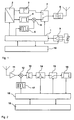
- the apparatus shown in FIG. 1 for the wireless transmission of data, in particular via radio has a control unit 1, to which a measured value detection 9 with sensors for recording consumption values, a memory 10 for storing in particular the consumption values and a transmitter 8 for transmitting the consumption values are connected.
- the transmitter 8 is a high-frequency transmitter with modulator and antenna.
- the present invention is not limited to a consumption meter for remote reading of home consumption data, but may generally be applied to the transmission of measurements or data to be received in various types of reception, in particular both from stationary and mobile receivers. This also applies to a wired transmission.
- the control unit 1 processes the measured values supplied to it by the measured value detection 9 and stores them as data to be transmitted in the memory 10. For transmitting the data, the control unit combines radio telegrams with the information to be sent, in particular the consumption values, but also further information such as Device identification, a time or the like., May contain. Furthermore, the control device 1 prepares the data to be transmitted for transmission by the transmitter 8 and forwards it to it. In this case, the control device 1 uses two different transmission modes, which are optimized once for a stationary and once for a mobile reception.
- the transmitters 8 should have a sufficient but small range for the mobile reception since the mobile reading devices are brought into the vicinity of the transmitters 8 during reading. Because such a manual reading usually takes place comparatively rarely, short radio telegrams with a high transmission frequency in the reading period and larger amounts of data should be transmitted so that all relevant information is contained in one or a few successive radio telegrams.
- the same transmitter 8 should have a high range when using stationary receivers in order to reach more distant receiver can. If the transmission frequency is low, several short or longer radio telegrams can be sent out with a small amount of data and the information collected in the stationary receiver.
- the same transmission power and the same transmission frequency for both modes should be used.
- the transmitter 8 is designed so that it is able to operate with the highest possible data rates (chip rates) by specifying a desired transmission step clock for the transmitter 8.
- the radio messages are made as redundant as possible while utilizing the bandwidth.
- a channel coding is selected, such as, for example, data whitening (bitwise superimposition of the user data stream with a pseudo-random binary stream having the same clock rate), efficient RLL coding or another, DC-free or DC-low coding method in which a data bit to be transmitted is essentially one or more is assigned to a few transmission step files (chips).
- chips transmission step files
- a radio telegram compiled by the control unit 1 is fed to a parallel / serial converter 2, which decomposes the radio telegram into a sequence of signals which follow one another in time.
- These Signal sequence is translated into signals to be transmitted in a channel coder and signal conditioner 3 for mobile telegrams for mobile reading, which predefines the chip rate and fed to the transmitter 8 via a switched from the control unit 1 signal multiplexer 7 for operation or transmission mode switching mobile / stationary.
- the channel encoder 3 the efficient channel coding for the mobile reading is applied.
- the same transmitter 8 with the same or a different chip rate is now used.
- the higher range in stationary operation is achieved according to the invention by a Sp Dahlbandmaschinen.
- Spread spectrum techniques which offer good interference suppression despite high bandwidth requirements, are for example time-division multiplexing (TDM), frequency division multiplexing (eg frequency hopping) or code division multiplexing (CDM).
- TDM time-division multiplexing
- CDM code division multiplexing
- Coordinated time and frequency multiplexing methods can typically only be used effectively in bidirectional systems since a synchronization mechanism must be implemented.
- Radio-readable consumption recording devices often have only one transmission part and, for reasons of cost, dispense with a radio receiver. A synchronization method is thus not feasible on the side of the detection devices.
- each individual data bit or a group of data bits is transmitted as a specific sequence of several chips. This is illustrated in the first line of Fig. 3, which shows a payload data bit which is multiplied in the spread spectrum method according to the code division multiple access principle with a chip sequence of thirty-two chips. Instead of a chip with the user data information Thirty-two chips are transmitted with predetermined data values.
- control unit 1 This is done in the control unit 1 by shaping the payload information in a signal shaper 4 for radio telegrams for the stationary reading as a signal with the 32-times chip length.
- This signal is superimposed with the given chip sequence of thirty-two chips from a CDM sequence generator 5 in a multiplier unit 6 by multiplying the two signals.
- the signal thus generated is fed via the signal multiplexer 7 to the transmitter 8 and interpreted accordingly by the receiver.
- G [ d B ] 10 ⁇ log ⁇ ( Chip data rate [ chip / s ] usable data [ bit / s ] )
- the process gain is shown in the bottom line of FIG.
- the stationary radio receiver requires a correlator, in which the input signal is multiplied chip-synchronously with an identical chip sequence or sequence as in the transmitter 8 after an adjustment phase and the resulting signal is integrated.
- the receiver shown in FIG. 2 has a control unit 18 with a memory unit 19 and a receiver 11 with a high-frequency input amplifier.
- the received signal is multiplied in a multiplication unit 12 by the chip sequence used in the transmission from a CMD sequence generator 17 and then summed up or integrated in an integrator 13.
- a synchronous detector 14 cooperating with the control unit 18 and a switch 15 controlled by the control unit 18, the useful data signal is reconstructed in a regenerator 16 and further processed by the control unit 18 and / or stored in the memory unit 19 for later use.
- the receiving side despreading of the useful signal existing interference signals are spread.
- the energy of the interference signal is thus distributed to the full bandwidth and correspondingly low is the interference component, which falls within the bandwidth of the filter in the correlator.
- the useful signal is despread, so that its energy falls completely in the bandwidth of the filter in the correlator. This process is based on the typical process gain for spread spectrum techniques.
- the autocorrelation functions of suitable code sequences only have a maximum when the code sequence is in-phase with itself.
- a sequence with the desired properties is, for example, the 11-chip Barker code 10110111000 known from the IEEE 802.11. If the binary 0 is assigned the signal value -1, then the autocorrelation function (AKF) or cross-correlation function shown in FIG. 4 is obtained (KKF) with the inverted sequence. Chip sequences with the property shown are suitable for processing with a correlation receiver.
- the consumption data can additionally be compressed by a suitable compression method.
- a known method for data reduction forms, for example, a chain of differential values from numerical data, wherein the difference values are scaled to a shortened binary representation via a common scaling factor.
- the time division multiplexing method for operating mode control is superimposed on the switchable code division multiplex method for range control.
- short radio telegrams are sent in short transmission intervals in the second transmission mode with efficient channel coding. Short radio telegrams can be achieved in the mobile reading case by omitting the CDM coding by utilizing the full bandwidth for data transmission.
- the transmitter 8 of a battery-powered consumption meter can be made particularly inexpensive if it can be dispensed with a charge pump for the increased transmission power requirements and instead a direct buffering in the form of a backup capacitor is used in parallel to the battery.
- Advantage of this circuit variant is that no converter losses to book and so the available battery capacity is better utilized.
- the thereby available, comparatively small voltage swing allows only a limited buffer time for the supply of the transmitter 8. This means that the length of the radio messages is limited in this circuit variant and is usually designed for the needs of mobile radio reading with short radio messages. If CDM coding (code division multiplex coding) is applied via the radio telegram at the same chip rate, then the transmittable data quantity is reduced by the factor corresponding to the ratio of chips per bit (see also FIG.
- the individual radiotelegrams of the multi-frame sequence are composed of three essential components: a device identification that is unique at least for the reception area, a sequence number and a user data part.
- the timers and clocks integrated in the control unit 1 of the transmitters and the control unit 18 of the stationary receivers have timing tolerances. To compensate for these timing tolerances of transmitters and stationary receivers, it is assumed that the timers of the transmitters are subject to age, production and temperature deviations.
- the consumption detection devices contain timers derived from an oscillation quartz frequency.
- the tolerances of such oscillating crystals are typically of the order of magnitude of ⁇ 100 ppm, that is to say at a maximum of approximately 53 minutes per year. The longer the total operating time of such devices, the lower the permissible deviation of the used oscillating crystals must be selected.
- TCXO temperature compensation
- DCF77 time signal receiver
- a time control in the transmitters and the stationary receivers should enable the following reading scenarios for a consumption reading: 1 to 7 days per week mobile reception at selected times of day.
- a typical application provides that accounting-relevant data is available after a programmable key date and that a mobile meter reading takes place after the key date.
- the period after reaching the cut-off date may be a few days, weeks, or months, depending on how often meter-readable key date values are generated.
- the radio messages for mobile reception are to be sent at short intervals. Outside of these periods preferred for a mobile reading, the frequency of the radio transmission should be reduced. This method avoids an unnecessarily high transmission current requirement in the majority of battery-operated measuring and transmitting devices.
- a transmission scheme which avoids the overlapping of time intervals for the transmission of radio messages for the reception with a mobile receiver and the reception with a stationary receiver is preferred.
- This temporal separation of the radio reading modes is advantageous because with a large number of transmitters and a high transmission frequency in periods of mobile readings of the radio channel is heavily loaded and the self-collision rate of the radio messages leads to range losses.
- an undisturbed transmission channel is needed in order to achieve high ranges.
- cyclically repeating time or subsections t m for the mobile reading and also cyclically repeating time or subsections t s for the reading with stationary receivers are defined.
- buffer times t a are inserted for compensating variations in the course of the timers.
- the buffer times t a are chosen so that they are at most completely used up by timer tolerances at the end of the life. used up in this sense means that the transmission time intervals t m and t s are continuously increased, with the buffer times t a lying between t m and t s correspondingly reduced, so that a predetermined total cycle duration t z remains unchanged.
- the total cycle time t z may be, for example, a day, a week, a month or a year.
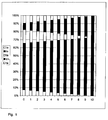
- a corresponding transmission scheme is shown in Fig. 5 for a period of use of 10 years.
- the percentage refers to the proportion of the total cycle time t z .
- FIG. 6 a transmission scheme is given on a daily basis, with the columns "years" and “weeks” meaning the duration of use in years plus weeks.
- the individual time or subsections t s , t m and buffer times t a are each in hours.
- An overview of the permissible operating time in Years without overlapping the transmission time intervals t m and t s for different timing tolerances and given buffer time t a (4h) is shown in FIG. 7.
- the cycle time t z 24 hours or exactly one day.
- the stationary receiver switches on in this example at selected times only for a maximum of the initial transmission time t s , so here for a maximum of 2 hours.
- the receiver does not increase its receive window over the duration of use, since the receiver power requirement is a critical factor in battery operation.
- the time-controlled switching on of the receiver can be reduced to a few time intervals t s adapted to the reading frequency in order to further reduce the power consumption of the receiver.
- the timing tolerances of the stationary receiver are completely absorbed by the transmission scheme in this proposal.
- the transmission time intervals t s for the stationary reading are increased stepwise over the period of use by the amount resulting from the cumulative maximum timer tolerances of sender and receiver.
- the transmission time intervals t s for the steady-state reading can be selected to be constant.
- the receiving window is thereby successively increased over the period of use of the system so that the transmission time intervals t s incl. All timer tolerances of transmitter and receiver find space in it.
- timing tolerances still have to be taken into account since the mobile reading is on oriented to absolute times.
- the transmission time intervals t m must therefore be adjusted depending on the tolerances of the transmitter clocks over the period of use.
- one or more selected days of the week may be reserved for inpatient reading, e.g. Sunday, and the other days of the week are reserved for mobile reading.
- the buffer times t a between the transmission sections t m and t s can be further increased, so that can reach very long periods and / or very inexpensive quartz crystals with low accuracy can be used as a timer.
- the method according to the invention for the radio transmission of data for stationary reception can be used without changes of the hardware. All features of the stationary variant are with the Characteristics of the mobile variant compatible. The same transmission rate, the same radio telegram length, the same RF modulation type and the same transmission power can be used. The range gain in stationary reception is achieved exclusively by the use of a code multiplex coding. It can be implemented as a pure software solution in the control devices of the devices without hardware modification. This is possible with little effort.
- the measuring devices can be read at any time both with a mobile radio receiver and via (subsequently installed) stationary receivers (in the building).
- the coexistence of two types of meters for reading with mobile receivers or with stationary receivers can be attributed to a universal data readout, without additional electronic components, for example, must be provided to increase the transmission power. This helps to reduce manufacturing and logistics costs.
Landscapes
- Engineering & Computer Science (AREA)
- Computer Networks & Wireless Communication (AREA)
- Signal Processing (AREA)
- Mobile Radio Communication Systems (AREA)
- Communication Control (AREA)
Priority Applications (1)
| Application Number | Priority Date | Filing Date | Title |
|---|---|---|---|
| PL05017359T PL1630980T5 (pl) | 2004-08-27 | 2005-08-10 | Sposób i urządzenie do transmisji danych z dwoma różnymi trybami nadawczymi |
Applications Claiming Priority (1)
| Application Number | Priority Date | Filing Date | Title |
|---|---|---|---|
| DE102004041421A DE102004041421C5 (de) | 2004-08-27 | 2004-08-27 | Verfahren und Vorrichtung zur Funkübertragung von Daten |
Publications (4)
| Publication Number | Publication Date |
|---|---|
| EP1630980A2 true EP1630980A2 (fr) | 2006-03-01 |
| EP1630980A3 EP1630980A3 (fr) | 2007-12-05 |
| EP1630980B1 EP1630980B1 (fr) | 2009-11-04 |
| EP1630980B2 EP1630980B2 (fr) | 2013-03-06 |
Family
ID=34937950
Family Applications (1)
| Application Number | Title | Priority Date | Filing Date |
|---|---|---|---|
| EP05017359A Expired - Lifetime EP1630980B2 (fr) | 2004-08-27 | 2005-08-10 | Procédé et dispositif de transmission de données par deux modes de transmission différents |
Country Status (5)
| Country | Link |
|---|---|
| EP (1) | EP1630980B2 (fr) |
| AT (1) | ATE447800T1 (fr) |
| DE (2) | DE102004041421C5 (fr) |
| DK (1) | DK1630980T4 (fr) |
| PL (1) | PL1630980T5 (fr) |
Families Citing this family (6)
| Publication number | Priority date | Publication date | Assignee | Title |
|---|---|---|---|---|
| DE102010005587B4 (de) * | 2010-01-22 | 2019-11-14 | Diehl Metering Systems Gmbh | Bidirektionales Funk-Datenübertragungsverfahren |
| DE102011101314A1 (de) | 2011-05-12 | 2012-11-15 | Hydrometer Electronic Gmbh | Verfahren und Einrichtung zum Übermitteln von Verbrauchsdaten |
| DE102017004888B4 (de) | 2017-05-20 | 2018-11-29 | Diehl Metering Systems Gmbh | Verfahren zum Betrieb eines Versorgungssystems |
| DE102017005625B4 (de) | 2017-06-14 | 2018-12-27 | Diehl Metering Systems Gmbh | Verfahren zum Betrieb eines elektronischen Datenerfassungsgeräts und Datenerfassungsgerät |
| DE102017119629B4 (de) | 2017-08-28 | 2024-06-06 | Techem Energy Services Gmbh | Verfahren zur Funkübertragung von Daten in einem Erfassungssystem sowie Sensorsende- und Empfangsgerät |
| DE102018133076B3 (de) * | 2018-12-20 | 2020-04-09 | Qundis Gmbh | Verbrauchswerterfassungseinheit mit zumindest einer Funkschnittstelle |
Citations (2)
| Publication number | Priority date | Publication date | Assignee | Title |
|---|---|---|---|---|
| WO2001048490A2 (fr) | 1999-12-29 | 2001-07-05 | Siemens Power Transmission & Distribution, Inc. | Dispositif de radiocommunication adaptatif pour compteur |
| DE10148275A1 (de) | 2001-05-21 | 2003-02-06 | Techem Service Ag | Verfahren zum Kodieren und Dekodieren von Datenströmen |
Family Cites Families (5)
| Publication number | Priority date | Publication date | Assignee | Title |
|---|---|---|---|---|
| US5438329A (en) * | 1993-06-04 | 1995-08-01 | M & Fc Holding Company, Inc. | Duplex bi-directional multi-mode remote instrument reading and telemetry system |
| KR100266806B1 (ko) * | 1996-12-11 | 2000-09-15 | 윤종용 | 휴대용무선통신단말기의전력제어회로및방법 |
| US5923269A (en) * | 1997-06-06 | 1999-07-13 | Abb Power T&D Company Inc. | Energy meter with multiple protocols for communication with local and wide area networks |
| DE10133367C2 (de) * | 2001-07-10 | 2003-10-23 | Horst Ziegler | Vebrauchszähler mit einer Funksendeeinrichtung zur Funkübertragung von Zählerstandsinformationen |
| DE10133366C2 (de) * | 2001-07-10 | 2003-11-06 | Horst Ziegler | Verfahren zur Erfassung von Zählerstandsdaten und Verbrauchsdaten-Erfassungssystem |
-
2004
- 2004-08-27 DE DE102004041421A patent/DE102004041421C5/de not_active Expired - Fee Related
-
2005
- 2005-08-10 EP EP05017359A patent/EP1630980B2/fr not_active Expired - Lifetime
- 2005-08-10 PL PL05017359T patent/PL1630980T5/pl unknown
- 2005-08-10 DK DK05017359.0T patent/DK1630980T4/da active
- 2005-08-10 AT AT05017359T patent/ATE447800T1/de active
- 2005-08-10 DE DE502005008433T patent/DE502005008433D1/de not_active Expired - Lifetime
Patent Citations (2)
| Publication number | Priority date | Publication date | Assignee | Title |
|---|---|---|---|---|
| WO2001048490A2 (fr) | 1999-12-29 | 2001-07-05 | Siemens Power Transmission & Distribution, Inc. | Dispositif de radiocommunication adaptatif pour compteur |
| DE10148275A1 (de) | 2001-05-21 | 2003-02-06 | Techem Service Ag | Verfahren zum Kodieren und Dekodieren von Datenströmen |
Also Published As
| Publication number | Publication date |
|---|---|
| ATE447800T1 (de) | 2009-11-15 |
| PL1630980T5 (pl) | 2013-08-30 |
| EP1630980A3 (fr) | 2007-12-05 |
| EP1630980B1 (fr) | 2009-11-04 |
| DK1630980T3 (da) | 2010-02-15 |
| DE502005008433D1 (de) | 2009-12-17 |
| DE102004041421B4 (de) | 2009-01-22 |
| DE102004041421A1 (de) | 2006-03-09 |
| DK1630980T4 (da) | 2013-05-27 |
| PL1630980T3 (pl) | 2010-10-29 |
| EP1630980B2 (fr) | 2013-03-06 |
| DE102004041421C5 (de) | 2011-08-18 |
Similar Documents
| Publication | Publication Date | Title |
|---|---|---|
| DE60111175T2 (de) | Energiesparschaltung eines empfängers | |
| EP2752060B1 (fr) | Concept pour la transmission bidirectionnelle de données entre une station de base et un noeud | |
| EP3474563B1 (fr) | Procédé de transmission de données | |
| EP2591557A1 (fr) | Système de réception basse consommation pour la réception sans fil de données | |
| EP4187992A1 (fr) | Procédé de fonctionnement d'un système de transmission radio et agencement d'un système de transmission radio | |
| EP1630980B1 (fr) | Procédé et dispositif de transmission de données par deux modes de transmission différents | |
| DE102004005340A1 (de) | Verfahren zur Gewinnung von Zeitinformationen, Empfängerschaltung und Funkuhr | |
| DE19824471B4 (de) | Verfahren zur Übertragung von Daten | |
| EP1791100B1 (fr) | Système de transmission sans fil avec stabilité de fréquence de diffusion compensé et recherche de fréquence de réception correspondante | |
| DE102017119629B4 (de) | Verfahren zur Funkübertragung von Daten in einem Erfassungssystem sowie Sensorsende- und Empfangsgerät | |
| DE102019005681A1 (de) | Verfahren zum bidirektionalen Übertragen von Daten, insbesondere Sensordaten sowie funkfähiger Knoten | |
| EP1750475B1 (fr) | Système de transmission de données et procédé de fonctionnement d'un système de transmission de données | |
| DE60130643T2 (de) | Sender-Empfänger für CDMA-Kommunikation mit Driftkorrektur einer Chipzählvorrichtung | |
| EP3579624B1 (fr) | Procédé de fonctionnement d'un système de transmission radio ainsi qu'agencement d'un système de transmission radio | |
| DE102022101405A1 (de) | Verfahren zum Betrieb eines Knotens in einem Funknetzwerk | |
| DE10238692A1 (de) | Verfahren zum unidirektionalen Übertragen von Meßdaten | |
| EP1765027A2 (fr) | Radio système et récepteur primaire pour un tel système | |
| EP1705846B1 (fr) | Méthode pour la transmission sans fil de données et compteur de consommation électronique | |
| EP3917152B1 (fr) | Procédé de transmission de données entre un noeud et une station de base dans un système de communication, ainsi que système de communication | |
| DE102017127242B4 (de) | Verbrauchswertsendeeinheit und Verfahren zu deren Betrieb, Verbrauchswertempfangseinheit und Verfahren zu deren Betrieb sowie Sender-Empfänger-Anordnung und Verfahren zu deren Betrieb | |
| EP1791255B1 (fr) | Système de radiocommunication | |
| DE4118387C2 (de) | Synchronisationseinrichtung für eine Schaltuhr | |
| EP4683343A1 (fr) | Emetteur radio | |
| EP3487184A1 (fr) | Unité émettrice de la valeur de consommation et son procédé de fonctionnement, unité réceptrice de la valeur de consommation et son procédé de fonctionnement ainsi que dispositif émetteur-récepteur et son procédé de fonctionnement | |
| CH689929A5 (de) | Verfahren zur Informationsübertragung in Rundsteuersystemen. |
Legal Events
| Date | Code | Title | Description |
|---|---|---|---|
| PUAI | Public reference made under article 153(3) epc to a published international application that has entered the european phase |
Free format text: ORIGINAL CODE: 0009012 |
|
| AK | Designated contracting states |
Kind code of ref document: A2 Designated state(s): AT BE BG CH CY CZ DE DK EE ES FI FR GB GR HU IE IS IT LI LT LU LV MC NL PL PT RO SE SI SK TR |
|
| AX | Request for extension of the european patent |
Extension state: AL BA HR MK YU |
|
| PUAL | Search report despatched |
Free format text: ORIGINAL CODE: 0009013 |
|
| AK | Designated contracting states |
Kind code of ref document: A3 Designated state(s): AT BE BG CH CY CZ DE DK EE ES FI FR GB GR HU IE IS IT LI LT LU LV MC NL PL PT RO SE SI SK TR |
|
| AX | Request for extension of the european patent |
Extension state: AL BA HR MK YU |
|
| RIC1 | Information provided on ipc code assigned before grant |
Ipc: G08C 17/02 20060101ALI20071031BHEP Ipc: H04B 7/26 20060101AFI20050922BHEP |
|
| 17P | Request for examination filed |
Effective date: 20080520 |
|
| 17Q | First examination report despatched |
Effective date: 20080703 |
|
| AKX | Designation fees paid |
Designated state(s): AT BE BG CH CY CZ DE DK EE ES FI FR GB GR HU IE IS IT LI LT LU LV MC NL PL PT RO SE SI SK TR |
|
| GRAP | Despatch of communication of intention to grant a patent |
Free format text: ORIGINAL CODE: EPIDOSNIGR1 |
|
| GRAS | Grant fee paid |
Free format text: ORIGINAL CODE: EPIDOSNIGR3 |
|
| GRAA | (expected) grant |
Free format text: ORIGINAL CODE: 0009210 |
|
| AK | Designated contracting states |
Kind code of ref document: B1 Designated state(s): AT BE BG CH CY CZ DE DK EE ES FI FR GB GR HU IE IS IT LI LT LU LV MC NL PL PT RO SE SI SK TR |
|
| REG | Reference to a national code |
Ref country code: GB Ref legal event code: FG4D Free format text: NOT ENGLISH |
|
| REG | Reference to a national code |
Ref country code: CH Ref legal event code: EP |
|
| REG | Reference to a national code |
Ref country code: CH Ref legal event code: NV Representative=s name: BOHEST AG |
|
| REG | Reference to a national code |
Ref country code: IE Ref legal event code: FG4D |
|
| REF | Corresponds to: |
Ref document number: 502005008433 Country of ref document: DE Date of ref document: 20091217 Kind code of ref document: P |
|
| REG | Reference to a national code |
Ref country code: RO Ref legal event code: EPE |
|
| REG | Reference to a national code |
Ref country code: DK Ref legal event code: T3 |
|
| NLV1 | Nl: lapsed or annulled due to failure to fulfill the requirements of art. 29p and 29m of the patents act | ||
| LTIE | Lt: invalidation of european patent or patent extension |
Effective date: 20091104 |
|
| PG25 | Lapsed in a contracting state [announced via postgrant information from national office to epo] |
Ref country code: SE Free format text: LAPSE BECAUSE OF FAILURE TO SUBMIT A TRANSLATION OF THE DESCRIPTION OR TO PAY THE FEE WITHIN THE PRESCRIBED TIME-LIMIT Effective date: 20091104 Ref country code: PT Free format text: LAPSE BECAUSE OF FAILURE TO SUBMIT A TRANSLATION OF THE DESCRIPTION OR TO PAY THE FEE WITHIN THE PRESCRIBED TIME-LIMIT Effective date: 20100304 Ref country code: LT Free format text: LAPSE BECAUSE OF FAILURE TO SUBMIT A TRANSLATION OF THE DESCRIPTION OR TO PAY THE FEE WITHIN THE PRESCRIBED TIME-LIMIT Effective date: 20091104 Ref country code: ES Free format text: LAPSE BECAUSE OF FAILURE TO SUBMIT A TRANSLATION OF THE DESCRIPTION OR TO PAY THE FEE WITHIN THE PRESCRIBED TIME-LIMIT Effective date: 20100215 Ref country code: FI Free format text: LAPSE BECAUSE OF FAILURE TO SUBMIT A TRANSLATION OF THE DESCRIPTION OR TO PAY THE FEE WITHIN THE PRESCRIBED TIME-LIMIT Effective date: 20091104 Ref country code: IS Free format text: LAPSE BECAUSE OF FAILURE TO SUBMIT A TRANSLATION OF THE DESCRIPTION OR TO PAY THE FEE WITHIN THE PRESCRIBED TIME-LIMIT Effective date: 20100304 |
|
| REG | Reference to a national code |
Ref country code: IE Ref legal event code: FD4D |
|
| PG25 | Lapsed in a contracting state [announced via postgrant information from national office to epo] |
Ref country code: LV Free format text: LAPSE BECAUSE OF FAILURE TO SUBMIT A TRANSLATION OF THE DESCRIPTION OR TO PAY THE FEE WITHIN THE PRESCRIBED TIME-LIMIT Effective date: 20091104 Ref country code: SI Free format text: LAPSE BECAUSE OF FAILURE TO SUBMIT A TRANSLATION OF THE DESCRIPTION OR TO PAY THE FEE WITHIN THE PRESCRIBED TIME-LIMIT Effective date: 20091104 Ref country code: CY Free format text: LAPSE BECAUSE OF FAILURE TO SUBMIT A TRANSLATION OF THE DESCRIPTION OR TO PAY THE FEE WITHIN THE PRESCRIBED TIME-LIMIT Effective date: 20091104 |
|
| PG25 | Lapsed in a contracting state [announced via postgrant information from national office to epo] |
Ref country code: EE Free format text: LAPSE BECAUSE OF FAILURE TO SUBMIT A TRANSLATION OF THE DESCRIPTION OR TO PAY THE FEE WITHIN THE PRESCRIBED TIME-LIMIT Effective date: 20091104 Ref country code: IE Free format text: LAPSE BECAUSE OF FAILURE TO SUBMIT A TRANSLATION OF THE DESCRIPTION OR TO PAY THE FEE WITHIN THE PRESCRIBED TIME-LIMIT Effective date: 20091104 Ref country code: BG Free format text: LAPSE BECAUSE OF FAILURE TO SUBMIT A TRANSLATION OF THE DESCRIPTION OR TO PAY THE FEE WITHIN THE PRESCRIBED TIME-LIMIT Effective date: 20100204 |
|
| PLBI | Opposition filed |
Free format text: ORIGINAL CODE: 0009260 |
|
| PG25 | Lapsed in a contracting state [announced via postgrant information from national office to epo] |
Ref country code: SK Free format text: LAPSE BECAUSE OF FAILURE TO SUBMIT A TRANSLATION OF THE DESCRIPTION OR TO PAY THE FEE WITHIN THE PRESCRIBED TIME-LIMIT Effective date: 20091104 |
|
| PLAX | Notice of opposition and request to file observation + time limit sent |
Free format text: ORIGINAL CODE: EPIDOSNOBS2 |
|
| 26 | Opposition filed |
Opponent name: ISTA INTERNATIONAL GMBH Effective date: 20100804 |
|
| PG25 | Lapsed in a contracting state [announced via postgrant information from national office to epo] |
Ref country code: GR Free format text: LAPSE BECAUSE OF FAILURE TO SUBMIT A TRANSLATION OF THE DESCRIPTION OR TO PAY THE FEE WITHIN THE PRESCRIBED TIME-LIMIT Effective date: 20100205 |
|
| REG | Reference to a national code |
Ref country code: PL Ref legal event code: T3 |
|
| PLAF | Information modified related to communication of a notice of opposition and request to file observations + time limit |
Free format text: ORIGINAL CODE: EPIDOSCOBS2 |
|
| PG25 | Lapsed in a contracting state [announced via postgrant information from national office to epo] |
Ref country code: MC Free format text: LAPSE BECAUSE OF NON-PAYMENT OF DUE FEES Effective date: 20100831 Ref country code: IT Free format text: LAPSE BECAUSE OF FAILURE TO SUBMIT A TRANSLATION OF THE DESCRIPTION OR TO PAY THE FEE WITHIN THE PRESCRIBED TIME-LIMIT Effective date: 20091104 |
|
| PLBB | Reply of patent proprietor to notice(s) of opposition received |
Free format text: ORIGINAL CODE: EPIDOSNOBS3 |
|
| PLAS | Information related to reply of patent proprietor to notice(s) of opposition deleted |
Free format text: ORIGINAL CODE: EPIDOSDOBS3 |
|
| GBPC | Gb: european patent ceased through non-payment of renewal fee |
Effective date: 20100810 |
|
| PLBB | Reply of patent proprietor to notice(s) of opposition received |
Free format text: ORIGINAL CODE: EPIDOSNOBS3 |
|
| REG | Reference to a national code |
Ref country code: FR Ref legal event code: ST Effective date: 20110502 |
|
| PG25 | Lapsed in a contracting state [announced via postgrant information from national office to epo] |
Ref country code: FR Free format text: LAPSE BECAUSE OF NON-PAYMENT OF DUE FEES Effective date: 20100831 |
|
| PG25 | Lapsed in a contracting state [announced via postgrant information from national office to epo] |
Ref country code: GB Free format text: LAPSE BECAUSE OF NON-PAYMENT OF DUE FEES Effective date: 20100810 |
|
| PG25 | Lapsed in a contracting state [announced via postgrant information from national office to epo] |
Ref country code: HU Free format text: LAPSE BECAUSE OF FAILURE TO SUBMIT A TRANSLATION OF THE DESCRIPTION OR TO PAY THE FEE WITHIN THE PRESCRIBED TIME-LIMIT Effective date: 20100505 Ref country code: NL Free format text: LAPSE BECAUSE OF FAILURE TO SUBMIT A TRANSLATION OF THE DESCRIPTION OR TO PAY THE FEE WITHIN THE PRESCRIBED TIME-LIMIT Effective date: 20091104 Ref country code: LU Free format text: LAPSE BECAUSE OF NON-PAYMENT OF DUE FEES Effective date: 20100810 |
|
| PG25 | Lapsed in a contracting state [announced via postgrant information from national office to epo] |
Ref country code: TR Free format text: LAPSE BECAUSE OF FAILURE TO SUBMIT A TRANSLATION OF THE DESCRIPTION OR TO PAY THE FEE WITHIN THE PRESCRIBED TIME-LIMIT Effective date: 20091104 |
|
| PUAH | Patent maintained in amended form |
Free format text: ORIGINAL CODE: 0009272 |
|
| STAA | Information on the status of an ep patent application or granted ep patent |
Free format text: STATUS: PATENT MAINTAINED AS AMENDED |
|
| 27A | Patent maintained in amended form |
Effective date: 20130306 |
|
| AK | Designated contracting states |
Kind code of ref document: B2 Designated state(s): AT BE BG CH CY CZ DE DK EE ES FI FR GB GR HU IE IS IT LI LT LU LV MC NL PL PT RO SE SI SK TR |
|
| REG | Reference to a national code |
Ref country code: CH Ref legal event code: AELC |
|
| REG | Reference to a national code |
Ref country code: DE Ref legal event code: R102 Ref document number: 502005008433 Country of ref document: DE Effective date: 20130306 |
|
| REG | Reference to a national code |
Ref country code: DK Ref legal event code: T4 |
|
| PG25 | Lapsed in a contracting state [announced via postgrant information from national office to epo] |
Ref country code: LV Free format text: LAPSE BECAUSE OF FAILURE TO SUBMIT A TRANSLATION OF THE DESCRIPTION OR TO PAY THE FEE WITHIN THE PRESCRIBED TIME-LIMIT Effective date: 20130306 |
|
| REG | Reference to a national code |
Ref country code: PL Ref legal event code: T5 |
|
| REG | Reference to a national code |
Ref country code: CH Ref legal event code: PCAR Free format text: NEW ADDRESS: HOLBEINSTRASSE 36-38, 4051 BASEL (CH) |
|
| PGFP | Annual fee paid to national office [announced via postgrant information from national office to epo] |
Ref country code: CZ Payment date: 20160801 Year of fee payment: 12 |
|
| PGFP | Annual fee paid to national office [announced via postgrant information from national office to epo] |
Ref country code: BE Payment date: 20160824 Year of fee payment: 12 |
|
| PGFP | Annual fee paid to national office [announced via postgrant information from national office to epo] |
Ref country code: CH Payment date: 20170525 Year of fee payment: 13 |
|
| PGFP | Annual fee paid to national office [announced via postgrant information from national office to epo] |
Ref country code: DK Payment date: 20170824 Year of fee payment: 13 Ref country code: AT Payment date: 20170821 Year of fee payment: 13 |
|
| PG25 | Lapsed in a contracting state [announced via postgrant information from national office to epo] |
Ref country code: CZ Free format text: LAPSE BECAUSE OF NON-PAYMENT OF DUE FEES Effective date: 20170810 |
|
| REG | Reference to a national code |
Ref country code: BE Ref legal event code: MM Effective date: 20170831 |
|
| PG25 | Lapsed in a contracting state [announced via postgrant information from national office to epo] |
Ref country code: BE Free format text: LAPSE BECAUSE OF NON-PAYMENT OF DUE FEES Effective date: 20170831 |
|
| REG | Reference to a national code |
Ref country code: DK Ref legal event code: EBP Effective date: 20180831 |
|
| REG | Reference to a national code |
Ref country code: CH Ref legal event code: PL |
|
| REG | Reference to a national code |
Ref country code: AT Ref legal event code: MM01 Ref document number: 447800 Country of ref document: AT Kind code of ref document: T Effective date: 20180810 |
|
| PG25 | Lapsed in a contracting state [announced via postgrant information from national office to epo] |
Ref country code: LI Free format text: LAPSE BECAUSE OF NON-PAYMENT OF DUE FEES Effective date: 20180831 Ref country code: AT Free format text: LAPSE BECAUSE OF NON-PAYMENT OF DUE FEES Effective date: 20180810 Ref country code: CH Free format text: LAPSE BECAUSE OF NON-PAYMENT OF DUE FEES Effective date: 20180831 |
|
| PG25 | Lapsed in a contracting state [announced via postgrant information from national office to epo] |
Ref country code: DK Free format text: LAPSE BECAUSE OF NON-PAYMENT OF DUE FEES Effective date: 20180831 |
|
| PGFP | Annual fee paid to national office [announced via postgrant information from national office to epo] |
Ref country code: RO Payment date: 20190806 Year of fee payment: 15 |
|
| PGFP | Annual fee paid to national office [announced via postgrant information from national office to epo] |
Ref country code: PL Payment date: 20190723 Year of fee payment: 15 |
|
| PG25 | Lapsed in a contracting state [announced via postgrant information from national office to epo] |
Ref country code: RO Free format text: LAPSE BECAUSE OF NON-PAYMENT OF DUE FEES Effective date: 20200810 |
|
| REG | Reference to a national code |
Ref country code: DE Ref legal event code: R084 Ref document number: 502005008433 Country of ref document: DE |
|
| PG25 | Lapsed in a contracting state [announced via postgrant information from national office to epo] |
Ref country code: PL Free format text: LAPSE BECAUSE OF NON-PAYMENT OF DUE FEES Effective date: 20200810 |
|
| PGFP | Annual fee paid to national office [announced via postgrant information from national office to epo] |
Ref country code: DE Payment date: 20240926 Year of fee payment: 20 |
|
| REG | Reference to a national code |
Ref country code: DE Ref legal event code: R071 Ref document number: 502005008433 Country of ref document: DE |