EP1631138A2 - Unité de support - Google Patents
Unité de support Download PDFInfo
- Publication number
- EP1631138A2 EP1631138A2 EP05016520A EP05016520A EP1631138A2 EP 1631138 A2 EP1631138 A2 EP 1631138A2 EP 05016520 A EP05016520 A EP 05016520A EP 05016520 A EP05016520 A EP 05016520A EP 1631138 A2 EP1631138 A2 EP 1631138A2
- Authority
- EP
- European Patent Office
- Prior art keywords
- unit according
- support unit
- support
- clamping
- support elements
- Prior art date
- Legal status (The legal status is an assumption and is not a legal conclusion. Google has not performed a legal analysis and makes no representation as to the accuracy of the status listed.)
- Granted
Links
Images


Classifications
-
- H—ELECTRICITY
- H05—ELECTRIC TECHNIQUES NOT OTHERWISE PROVIDED FOR
- H05K—PRINTED CIRCUITS; CASINGS OR CONSTRUCTIONAL DETAILS OF ELECTRIC APPARATUS; MANUFACTURE OF ASSEMBLAGES OF ELECTRICAL COMPONENTS
- H05K13/00—Apparatus or processes specially adapted for manufacturing or adjusting assemblages of electric components
- H05K13/0061—Tools for holding the circuit boards during processing; handling transport of printed circuit boards
- H05K13/0069—Holders for printed circuit boards
-
- H—ELECTRICITY
- H05—ELECTRIC TECHNIQUES NOT OTHERWISE PROVIDED FOR
- H05K—PRINTED CIRCUITS; CASINGS OR CONSTRUCTIONAL DETAILS OF ELECTRIC APPARATUS; MANUFACTURE OF ASSEMBLAGES OF ELECTRICAL COMPONENTS
- H05K3/00—Apparatus or processes for manufacturing printed circuits
- H05K3/30—Assembling printed circuits with electric components, e.g. with resistors
- H05K3/32—Assembling printed circuits with electric components, e.g. with resistors electrically connecting electric components or wires to printed circuits
- H05K3/34—Assembling printed circuits with electric components, e.g. with resistors electrically connecting electric components or wires to printed circuits by soldering
- H05K3/341—Surface mounted components
- H05K3/3415—Surface mounted components on both sides of the substrate or combined with lead-in-hole components
Definitions
- the invention relates to a support unit for the support of an assembly on a height-varying surface contour, in particular for the support of component-mounted printed circuit boards, comprising a base housing in which a plurality of support elements are movable in the direction of their longitudinal direction between a retracted position and an extended position, displacement units, with which the support elements can be acted upon in the direction of the extended position, and fixing units, with which the support elements in their respective positions relative to the base housing can be fixed.
- the invention is therefore based on the object to improve a support unit of the generic type such that an advantageous fixation of the support elements is possible.
- the fixing units comprise clamping bodies acting on the support elements, which can be acted upon by an actuating device.
- the advantage of the solution according to the invention is the fact that the clamping body allow a simple way of fixing the support elements by frictional engagement and that also by the actuator these clamping body can be acted upon in a simple manner to cause them to set the support elements by clamping.
- the clamping body could be formed in various ways.
- the clamping body could be multi-part, designed in the manner of chucks facilities.
- a structurally particularly simple solution provides that the clamping body are designed as clamping sleeves.
- clamping sleeves could for example be made of metal and the support elements have clamping lamellae.
- clamping sleeves are made of an elastic material.
- the support elements can be set particularly favorably when the clamping sleeves are formed from a material having a high static friction on the support elements.
- the clamping sleeves are made of rubber, since such formed of rubber clamping sleeves high friction on the support elements can be realized.
- clamping sleeves are designed as rubber hose pieces, so that they can be produced in a simple manner by a rubber hose by burning of segments.
- a functionally reliable and structurally easy to implement solution provides that the actuator exerts a force on the clamping body by means of a pressurizable medium.
- the actuating device could, for example, have individual pistons which can be acted upon by the medium in order to act on the clamping bodies.
- the actuation has at least one element expandable by the medium, which acts on at least one of the clamping bodies.
- a solution in which the actuating device has an expandable hose body as an expandable element is particularly expedient.
- the hose body can run as desired.
- a structurally particularly expedient solution provides that the hose body has transverse to the longitudinal axes of the support elements and in particular passes laterally past the clamping bodies.
- the hose body could be meandering past the sprags.
- the hose body extends along a series of support elements and the clamping body can be acted upon by the hose body.
- the expandable element is provided on its side acting on the clamping body side with a wall stiffening.
- Such a wall stiffening creates the possibility of receiving the expansion movement over a large area from the expanding element and transferring it to the clamping body.
- the wall stiffening transmits an expansion of an extending beyond the clamping body portion of the expandable member on the clamping body.
- the wall stiffening could be carried out in various ways.
- the wall stiffener could be integrated into a wall of the expandable element. It is particularly favorable, however, if the wall reinforcement is formed as a separate element from the expandable element.
- the wall stiffening could enclose the expandable element similar to a half shell.
- a particularly simple embodiment provides that the wall stiffening is designed as a stiffening strip.
- Such a stiffening strip could be, for example, a plastic material strip or a metal strip.
- the stiffening strip is made of a partially flexible material, so that it can be adapted within limits to the shape of the expandable element.
- the stiffening strip is designed as a narrow steel strip made of spring steel or a partially flexible plastic.
- stiffening strip extends along the clamping body which can be acted upon by the expandable element of one of the rows of supporting elements.
- the base housing for receiving the clamping body and the expandable element comprises two housing parts.
- clamp body and the expanding element can be mounted in a simple manner within the base housing.
- the displacement units have a spring energy storage.
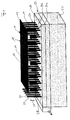
- FIG. 1 An embodiment of a support unit according to the invention, shown in Fig. 1, serves to support an assembly 10, which for example comprises a circuit board 12, on which components 14 are arranged, the overall relative to the board 12, a height-varying surface contour 16 result.
- assembly 10 which for example comprises a circuit board 12, on which components 14 are arranged, the overall relative to the board 12, a height-varying surface contour 16 result.
- a support unit 20 is provided as a whole, which comprises a base housing 22 in which a plurality of support members 24 are movably mounted in a displacement direction 26, wherein the support elements 24 extend with parallel shafts 28 and at a distance from each other via an upper surface 30 of the base housing 22, up to a support head 32, but at different distances is arranged from the top 30, depending on whether the support head 32 of one of the components 14 or the circuit board 12 is supported directly.
- the support elements 24 are arranged at a distance from one another in rows 34, which also extend parallel to each other at a distance from one another, so that in a defined surface pattern support elements 24 for supporting the assembly 10 are available.
- the support elements 24 are, as shown in Fig. 2, movably guided with their respective shaft 28 in the base housing 22 in the displacement direction 26, wherein a guide of the respective shaft 28 by guide surfaces 36, 38 of the base housing 22, preferably on both sides of a Whole with 40 designated clamping body are arranged.
- each shaft 28 can be acted upon in an end region 42 facing away from the support head 32 by an elastic force store 44 which is arranged in a recess 46 in the base housing 22 and with one end 48 on a shoulder 50 of the respective support element 24, for example formed by one on the shaft 28 held in the end portion 42 acts, while the force accumulator 44 is supported at its other end 52 at a bottom 53 of the recess 46.
- the arranged in the recess 46 power storage 54 and the shoulder 50 thus form a total of a displacement device 54 for each support member 24th
- the force accumulator 44 and the recess 46 are located on a side of the clamp body 40 facing away from the support head 32.
- the clamping body 40 is held immovably in the displacement direction 26 in the base housing 22, for example by arranging the same between two support shoulders 56, 58 formed by the base housing 22.
- the clamping body 40 as shown in Fig. 3, as the respective shaft 28 comprising sleeve 60 made of an elastic material, preferably formed from a piece of rubber hose, so that the shaft 28 passes through an inner opening 62 of the sleeve 60.
- the shaft 28 in the opening 62 of the sleeve 60 can be frictionally determined when the sleeve 60 acts in a radial direction to a longitudinal direction 64 of the shaft 28 directed force, which the sleeve 60 with on one side of the shaft 28 applies and thus creates a frictional connection between the shaft 28 and the sleeve 60.
- an actuator 70 which comprises an expandable tubular body 72, the jacket 74 thereof acts on the clamping body 40 in an expansion thereof.
- the expandable tubular body 72 is provided with a wall stiffening 76 which lies between the jacket 74 and the sleeve 60 and extends along the tubular body 72.
- the actuating device 70 serves to actuate the clamping body 40 of two adjacent rows 34a and 34b of support elements 24, wherein the expandable tubular body 72 between the two rows 34a and 34b transversely to the longitudinal direction 64 of the shafts 28 of the respective support elements 24 extends, preferably in a direction perpendicular to these lying plane 78.
- the hose body is located between the clamping bodies 40a, 40b of the support members 24 of the two rows, so that an expansion of the shell 77 of the hose body 72 on the lying on opposite sides of the expandable hose body 72 wall stiffeners 76a, 76b acts and on these on opposite sides of expandable hose body 72 arranged clamp body 40a, 40b acted upon.
- the clamping bodies 40a, 40b lie on opposite sides with respect to a longitudinal direction 80 of the expandable hose body 72, so that the jacket 74 of the expandable hose body 72 in the expanded state, as shown in Fig. 4, between the opposing wall stiffeners 76a, 76b clamped and thereby presses on this, in turn, with their sides facing away from the expandable hose body 72 act on the arranged on opposite sides of the hose body 72 clamp body 40a, 40b and the clamp body 40a, 40b act simultaneously.
- the expandable tubular body 72 and the wall stiffeners 76a and 76b are floating between the clamping bodies 40a, 40b of the two rows 34a, 34b of support members 24a, 24b, so that the expandable tubular body 72 itself between the clamping bodies 40a, 40b, centered and with in substantially the same force is applied to each of the clamping bodies 40a, 40b in a direction extending radially to the longitudinal direction 64 of the respective shaft 28, and thus frictionally secures the respective shank 28a, 28b in the opening 62a, 62b of the respective clamping body, so that the shaft 28 due to Fixing the clamp body 40 between the retaining shoulders 56 and 58 in the base housing 22 is also no longer movable in the direction of displacement 26 relative to the base housing 22.
- a passage 84 extending symmetrically to the plane 78 is preferably provided between receptacles 82a, 82b provided in the base housing 22 and holding shoulders 56 and 58 for the opposite clamping bodies 40a, 40b.
- 82b penetrates and extends between the two rows 34a, 34b of support members 24 over the entire longitudinal extent of the rows 34a, 34b of support members 24a, 24b.
- the aperture 84 is also still formed so that the wall stiffeners 76a, 76b are guided by a approximately parallel to the plane 78 extending bottom surface 86 and an approximately parallel to the plane 78 extending lid surface 88 of the opening 84.
- the opening 84 is formed symmetrically to the plane 78, so that the bottom surface 86 and the lid surface 88 are symmetrical to the plane 78.
- the expandable tubular body 72 is preferably approximately symmetrical about the plane 78 in the same manner as the wall stiffeners 76a and 76b.
- the distance of the bottom surface 86 is selected by the wall surface 88 at each breakthrough, that, as shown in Fig. 4, when expanded hose body 72 of the jacket 74 substantially abuts them, so that the expandable tubular body 72 in the expanded state Also supported on the bottom surface 86 and the lid surface 88, which are opposed to each other, and also the expanded tubular body 72 is supported on the transverse thereto wall stiffeners 76a and 76b in a direction approximately parallel to the bottom surface 86 or cover surface 88 extending direction on opposite sides ,
- the wall stiffeners 76a and 76b are urged by the jacket 74 of the expandable hose body 72 and moved apart to act on the clamp body 40a, 40b for fixing the shafts 28 of the support members 24.
- the support unit 20 now functions so that the forces exerted by the force accumulators 44 are sufficiently strong to extend these in the unloaded state of the support elements 24 this maximum of the base housing 22 and thus the support heads 32 at the maximum possible distance from the top 30 of the base housing 22nd to position.
- each of the support elements 24 supports the assembly 10 to be supported, for example either on the circuit board 10 or on a component 14, whereby the support elements 24 in support of the assembly 10 in a differently far extended from the base housing 22 Standing position.
- the energy storage 44 are preferably designed so that the sum of all the assembly 10 on the Oberfumbleenkontur 16 with their support heads 32 acting support elements 24 is able to carry the assembly in the unbeaten state.
- those support elements 24 which act on the surface contour 16 in its lowest point, so for example, the circuit board 12 directly, maximally extended from the base housing 22, that is, it is in its in Fig. 2 or 4 shown maximum extended position, while those supporting elements 24, which support one of the components 14 on the circuit board 12 with their support heads 32, are in a position partially retracted into the base housing 22.
- the support elements 24 can according to the invention in all positions, that is both in the maximum extended position and a maximum retracted position or an intermediate position by expanding the hose body 72 frictionally in the openings 62 of the clamping elements 40 and thus also fixed non-positively relative to the base housing 22 , so that the assembly 10 can be acted upon on its side 18 with additional forces, which can be taken over the sum of all support members 24 and their non-positive fixing relative to the base housing 22 from the base housing 22 and passed from the base housing 22 via a foot surface 90.
- the expandable hose body 72 is provided in the region of an end 92 with a pressure port 94 and closed in the region of an opposite end 96, for example via a blind plug 98.
- a pressurized medium over the pressure port 94, the hose body 72 is expandable in a simple manner by the feedable medium, wherein this medium may be a liquid or gaseous medium.
- air can be used for this purpose.
- the base housing 22 is preferably provided with a coincident with the plane 78 dividing plane 106, so that the receptacles 82 and the apertures 84 comprehensive area of the base housing 22 in two parts 112 and 116 can be disassembled to the clamping elements 40 and the actuator 70 with the hose body 72 and the wall stiffeners 76 easy to assemble, since the parting plane 106 preferably both the receptacles 82 and the apertures 84 cut approximately half.
- the support unit 20 For mounting the support unit 20 according to the invention in a device, for example in the area near the foot surface 90 holding elements 120 are provided, which may be formed either as threaded holes or as holding magnets to magnetically fix the support units on a substrate.
- each support member 24 is provided with a cap 122 made of electrically conductive plastic, so as not to damage the assembly 10, in particular components 14 thereof during support.
- a second embodiment of a support unit 20 according to the invention shown in Fig. 6 and Fig. 7, those elements which are identical to those of the first embodiment, provided with the same reference numerals, so that with respect to the description of the same fully to the comments on the first embodiment reference can be taken.
- no force accumulator 44 are arranged in the recesses 46, but the recesses 46 are connected via pressure channels 130 to a pressure port 132, via which a medium under pressure can be supplied to the recesses 46 in the region of its bottom 53.
- the support members 24 in the same manner as in the first embodiment, all position so that each of the module 10 can be applied to the supporting elements 24 rests with its support head 32 on the assembly 10 and supports them in the otherwise unloaded condition, so that the overall assembly can be supported by the totality of all arranged in the assembly 10 support elements 24.
- the force with which the support members 24 act on the assembly 10 by varying the pressure of the pressure port 132 and the pressure channels 130 the recesses 46 supplied medium set so that, depending on the weight of the assembly 10 is an adaptation of the Support elements 24 exerted forces is possible.
- the medium flowing past the flange bodies 134 in each case flows around the shaft 28 and flows through the guide surfaces 36, the clamping bodies 40 and the guide surfaces 38, so that the medium in the region of the upper side 30 of the base housing 22 emerges from this again.
- small forces acting on the support elements 24 can be adjusted in order to be able to act on components 14 of the assembly 10 that are sensitive to little force.
- a pressure generator 140 can be used, as shown in FIG. 8.
- This pressurization 140 includes a cylinder body 142 in which a cylinder chamber 144 is disposed, within which a piston 146 is movable.
- the volume of the cylinder chamber 144 can be variably increased and thus accommodate medium 148 or introduce into the interior 100 of the expandable hose body 72 to expand the jacket 74.
- the piston 146 is acted upon by a resilient force storage device 150 in the direction of a maximum cylinder chamber volume corresponding position, so that the piston 146 automatically has the tendency to always go into the position in which the cylinder chamber 144 has the largest volume.
- the piston is further acted upon by an urging device 152, which comprises a threaded spindle 154 which engages with its threaded portion 156 in an internal thread 158 of the cylinder body and with an extension 160 to the piston 146, wherein the extension 160 with a front end 162 on the piston 146 is applied, wherein the piston 146 in turn is held at the end 162 in abutment due to the resilient element 150.
- an urging device 152 which comprises a threaded spindle 154 which engages with its threaded portion 156 in an internal thread 158 of the cylinder body and with an extension 160 to the piston 146, wherein the extension 160 with a front end 162 on the piston 146 is applied, wherein the piston 146 in turn is held at the end 162 in abutment due to the resilient element 150.
- the threaded spindle 156 and thus the extension 160 can be moved in a displacement direction 168 and thus the piston 146 can be displaced in the opposite direction to the action of the resilient element 150 in the direction of a reduction of the cylinder chamber volume. so that thereby the medium 148 is transferred into the inner space 100 of the expandable hose body 72, which thereby expands and the clamping body 40 is applied.
- the end 162 can be moved in the direction of the force action of the resilient element 150, so that the piston moves in the direction of increasing the cylinder chamber volume position due to the action of the resilient element 150 and medium 148 is transferred from the interior 100 of the expandable hose body 72 in the cylinder chamber 44, so that the expandable tubular body 72 reduces its volume and no longer acts the clamping body 40.
- the loading device 152 comprises an eccentric body 172, which is mounted rotatably about a rotation axis 174 in the cylinder body 142.
- the eccentric body 172 in turn acts with its peripheral surface 176 on an end 178 of the plunger 166, which in turn acts in turn on the piston 146 with the end 162 in a known manner.
- the plunger 166 can now be displaced so that it moves the piston 146 into a position which reduces the cylinder chamber volume or allows it to increase in a cylinder chamber volume into which the piston 146 is movable due to the action of the resilient element 150 ,
- both a gaseous medium and a liquid medium that is, for example, air as a gaseous medium or oil as a liquid medium can be used.
Landscapes
- Engineering & Computer Science (AREA)
- Manufacturing & Machinery (AREA)
- Microelectronics & Electronic Packaging (AREA)
- Supports For Pipes And Cables (AREA)
- Jigs For Machine Tools (AREA)
- Actuator (AREA)
- Supply And Installment Of Electrical Components (AREA)
- Mounting Of Printed Circuit Boards And The Like (AREA)
- Sink And Installation For Waste Water (AREA)
- Supplying Of Containers To The Packaging Station (AREA)
- Centrifugal Separators (AREA)
Priority Applications (1)
| Application Number | Priority Date | Filing Date | Title |
|---|---|---|---|
| EP10182416.7A EP2265104B1 (fr) | 2004-08-02 | 2005-07-29 | Unité de support |
Applications Claiming Priority (1)
| Application Number | Priority Date | Filing Date | Title |
|---|---|---|---|
| DE102004037501A DE102004037501A1 (de) | 2004-08-02 | 2004-08-02 | Stützeinheit |
Related Child Applications (1)
| Application Number | Title | Priority Date | Filing Date |
|---|---|---|---|
| EP10182416.7 Division-Into | 2010-09-29 |
Publications (3)
| Publication Number | Publication Date |
|---|---|
| EP1631138A2 true EP1631138A2 (fr) | 2006-03-01 |
| EP1631138A3 EP1631138A3 (fr) | 2007-11-21 |
| EP1631138B1 EP1631138B1 (fr) | 2011-02-16 |
Family
ID=35355574
Family Applications (2)
| Application Number | Title | Priority Date | Filing Date |
|---|---|---|---|
| EP10182416.7A Expired - Lifetime EP2265104B1 (fr) | 2004-08-02 | 2005-07-29 | Unité de support |
| EP05016520A Expired - Lifetime EP1631138B1 (fr) | 2004-08-02 | 2005-07-29 | Unité de support |
Family Applications Before (1)
| Application Number | Title | Priority Date | Filing Date |
|---|---|---|---|
| EP10182416.7A Expired - Lifetime EP2265104B1 (fr) | 2004-08-02 | 2005-07-29 | Unité de support |
Country Status (3)
| Country | Link |
|---|---|
| EP (2) | EP2265104B1 (fr) |
| AT (1) | ATE498993T1 (fr) |
| DE (2) | DE102004037501A1 (fr) |
Cited By (2)
| Publication number | Priority date | Publication date | Assignee | Title |
|---|---|---|---|---|
| WO2011126559A1 (fr) * | 2010-04-05 | 2011-10-13 | Quik-Tool, Llc | Appareil de support de blocage de chevilles |
| FR2982603A1 (fr) * | 2011-11-15 | 2013-05-17 | Peugeot Citroen Automobiles Sa | Dispositif pour le maintien en position d'une piece sur un convoyeur de transfert |
Family Cites Families (4)
| Publication number | Priority date | Publication date | Assignee | Title |
|---|---|---|---|---|
| US5984293A (en) * | 1997-06-25 | 1999-11-16 | Mcms, Inc. | Apparatus for holding printed circuit board assemblies in manufacturing processes |
| SE514024C2 (sv) * | 1998-09-11 | 2000-12-11 | Ascom Tateco Ab | Stödanordning vid montering av komponenter på ett kretskort |
| US6726195B1 (en) * | 1998-10-13 | 2004-04-27 | Dek International Gmbh | Method for ensuring planarity when using a flexible, self conforming, workpiece support system |
| US6711797B1 (en) * | 1999-06-21 | 2004-03-30 | Dek International Gmbh | Hydraulic tooling fixture |
-
2004
- 2004-08-02 DE DE102004037501A patent/DE102004037501A1/de not_active Ceased
-
2005
- 2005-07-29 DE DE502005010974T patent/DE502005010974D1/de not_active Expired - Lifetime
- 2005-07-29 EP EP10182416.7A patent/EP2265104B1/fr not_active Expired - Lifetime
- 2005-07-29 AT AT05016520T patent/ATE498993T1/de active
- 2005-07-29 EP EP05016520A patent/EP1631138B1/fr not_active Expired - Lifetime
Cited By (3)
| Publication number | Priority date | Publication date | Assignee | Title |
|---|---|---|---|---|
| WO2011126559A1 (fr) * | 2010-04-05 | 2011-10-13 | Quik-Tool, Llc | Appareil de support de blocage de chevilles |
| US9138841B2 (en) | 2010-04-05 | 2015-09-22 | Quik-Tool, Llc | Pin locking support fixture |
| FR2982603A1 (fr) * | 2011-11-15 | 2013-05-17 | Peugeot Citroen Automobiles Sa | Dispositif pour le maintien en position d'une piece sur un convoyeur de transfert |
Also Published As
| Publication number | Publication date |
|---|---|
| EP2265104A2 (fr) | 2010-12-22 |
| EP2265104A3 (fr) | 2011-01-05 |
| EP1631138A3 (fr) | 2007-11-21 |
| EP1631138B1 (fr) | 2011-02-16 |
| DE502005010974D1 (de) | 2011-03-31 |
| ATE498993T1 (de) | 2011-03-15 |
| DE102004037501A1 (de) | 2006-03-16 |
| EP2265104B1 (fr) | 2013-05-29 |
Similar Documents
| Publication | Publication Date | Title |
|---|---|---|
| EP1970139B1 (fr) | Dispositif de prise destiné à la saisie et à la fixation de pièces usinées, en particuliers pour cintreuses | |
| DE3802703C2 (de) | Kolbenstangenlose Zylinderanordnung | |
| DE2734343C2 (de) | Werkbank mit Spanneinrichtung | |
| DE1290999B (de) | Vierwegkerbwerkzeug | |
| DE10106601B4 (de) | Führungseinrichtung für eine fluidbetätigte Spannzange | |
| DE102012002340A1 (de) | Einpressvorrichtung zum Einpressen einer Lagerhülse in eine Lageröffnung eines Motorbauteils | |
| WO1999006169A1 (fr) | Dispositif pour la separation par rupture de la barre et du chapeau d'une bielle | |
| DD240859A5 (de) | Maschinenschraubstock | |
| DE102013101083B4 (de) | Hilfswerkzeug zur Montage eines Stoßdämpfers | |
| DE19531523C2 (de) | Linearantrieb | |
| DE10162159B4 (de) | Linearstellglied mit Stoßdämpfungsmechanismus | |
| DE3506491A1 (de) | Druckmittelbetaetigter arbeitszylinder | |
| DE3151275A1 (de) | Befestigungsvorrichtung fuer werkzeuge | |
| DE10005321A1 (de) | Vorrichtung zur schwimmenden Spannung eines zu bearbeitenden Werkstückes | |
| DE2646759B2 (de) | Vorrichtung zum Entnehmen und zum Transport von Kunststoff-Hohlkörpern einer Blasform | |
| DE69700231T2 (de) | Selbstzentrierende Lünette mit einfahrbaren Greifarmen | |
| EP1056556B1 (fr) | Dispositif de sertissage a elements de pression et de serrage | |
| EP1631138B1 (fr) | Unité de support | |
| EP1245346A1 (fr) | Pince de préhension à machoires parallèles actionnées par deux vérins | |
| EP0107763B1 (fr) | Etau, en particulier pour machine-outil | |
| DE19858837B4 (de) | Presse zum Innenhochdruckumformen | |
| DE10156261C1 (de) | Greif- oder Spannvorrichtung | |
| DE19926330C2 (de) | Biegedorn für eine Biegevorrichtung und Biegeverfahren für Rohre | |
| DE102007004194A1 (de) | Spannvorrichtung | |
| EP3061553A1 (fr) | Dispositif de traitement de pieces a bord coupant comprenant un dispositif de serrage |
Legal Events
| Date | Code | Title | Description |
|---|---|---|---|
| PUAI | Public reference made under article 153(3) epc to a published international application that has entered the european phase |
Free format text: ORIGINAL CODE: 0009012 |
|
| AK | Designated contracting states |
Kind code of ref document: A2 Designated state(s): AT BE BG CH CY CZ DE DK EE ES FI FR GB GR HU IE IS IT LI LT LU LV MC NL PL PT RO SE SI SK TR |
|
| AX | Request for extension of the european patent |
Extension state: AL BA HR MK YU |
|
| PUAL | Search report despatched |
Free format text: ORIGINAL CODE: 0009013 |
|
| AK | Designated contracting states |
Kind code of ref document: A3 Designated state(s): AT BE BG CH CY CZ DE DK EE ES FI FR GB GR HU IE IS IT LI LT LU LV MC NL PL PT RO SE SI SK TR |
|
| AX | Request for extension of the european patent |
Extension state: AL BA HR MK YU |
|
| 17P | Request for examination filed |
Effective date: 20080328 |
|
| 17Q | First examination report despatched |
Effective date: 20080513 |
|
| AKX | Designation fees paid |
Designated state(s): AT BE BG CH CY CZ DE DK EE ES FI FR GB GR HU IE IS IT LI LT LU LV MC NL PL PT RO SE SI SK TR |
|
| GRAP | Despatch of communication of intention to grant a patent |
Free format text: ORIGINAL CODE: EPIDOSNIGR1 |
|
| GRAS | Grant fee paid |
Free format text: ORIGINAL CODE: EPIDOSNIGR3 |
|
| GRAA | (expected) grant |
Free format text: ORIGINAL CODE: 0009210 |
|
| AK | Designated contracting states |
Kind code of ref document: B1 Designated state(s): AT BE BG CH CY CZ DE DK EE ES FI FR GB GR HU IE IS IT LI LT LU LV MC NL PL PT RO SE SI SK TR |
|
| REG | Reference to a national code |
Ref country code: GB Ref legal event code: FG4D Free format text: NOT ENGLISH |
|
| REG | Reference to a national code |
Ref country code: CH Ref legal event code: EP |
|
| REG | Reference to a national code |
Ref country code: CH Ref legal event code: NV Representative=s name: KIRKER & CIE S.A. |
|
| REG | Reference to a national code |
Ref country code: IE Ref legal event code: FG4D Free format text: LANGUAGE OF EP DOCUMENT: GERMAN |
|
| REF | Corresponds to: |
Ref document number: 502005010974 Country of ref document: DE Date of ref document: 20110331 Kind code of ref document: P |
|
| REG | Reference to a national code |
Ref country code: DE Ref legal event code: R096 Ref document number: 502005010974 Country of ref document: DE Effective date: 20110331 |
|
| REG | Reference to a national code |
Ref country code: NL Ref legal event code: VDEP Effective date: 20110216 |
|
| LTIE | Lt: invalidation of european patent or patent extension |
Effective date: 20110216 |
|
| PG25 | Lapsed in a contracting state [announced via postgrant information from national office to epo] |
Ref country code: LV Free format text: LAPSE BECAUSE OF FAILURE TO SUBMIT A TRANSLATION OF THE DESCRIPTION OR TO PAY THE FEE WITHIN THE PRESCRIBED TIME-LIMIT Effective date: 20110216 Ref country code: LT Free format text: LAPSE BECAUSE OF FAILURE TO SUBMIT A TRANSLATION OF THE DESCRIPTION OR TO PAY THE FEE WITHIN THE PRESCRIBED TIME-LIMIT Effective date: 20110216 Ref country code: PT Free format text: LAPSE BECAUSE OF FAILURE TO SUBMIT A TRANSLATION OF THE DESCRIPTION OR TO PAY THE FEE WITHIN THE PRESCRIBED TIME-LIMIT Effective date: 20110616 Ref country code: GR Free format text: LAPSE BECAUSE OF FAILURE TO SUBMIT A TRANSLATION OF THE DESCRIPTION OR TO PAY THE FEE WITHIN THE PRESCRIBED TIME-LIMIT Effective date: 20110517 Ref country code: SE Free format text: LAPSE BECAUSE OF FAILURE TO SUBMIT A TRANSLATION OF THE DESCRIPTION OR TO PAY THE FEE WITHIN THE PRESCRIBED TIME-LIMIT Effective date: 20110216 Ref country code: ES Free format text: LAPSE BECAUSE OF FAILURE TO SUBMIT A TRANSLATION OF THE DESCRIPTION OR TO PAY THE FEE WITHIN THE PRESCRIBED TIME-LIMIT Effective date: 20110527 |
|
| PG25 | Lapsed in a contracting state [announced via postgrant information from national office to epo] |
Ref country code: FI Free format text: LAPSE BECAUSE OF FAILURE TO SUBMIT A TRANSLATION OF THE DESCRIPTION OR TO PAY THE FEE WITHIN THE PRESCRIBED TIME-LIMIT Effective date: 20110216 Ref country code: CY Free format text: LAPSE BECAUSE OF FAILURE TO SUBMIT A TRANSLATION OF THE DESCRIPTION OR TO PAY THE FEE WITHIN THE PRESCRIBED TIME-LIMIT Effective date: 20110216 Ref country code: SI Free format text: LAPSE BECAUSE OF FAILURE TO SUBMIT A TRANSLATION OF THE DESCRIPTION OR TO PAY THE FEE WITHIN THE PRESCRIBED TIME-LIMIT Effective date: 20110216 Ref country code: BG Free format text: LAPSE BECAUSE OF FAILURE TO SUBMIT A TRANSLATION OF THE DESCRIPTION OR TO PAY THE FEE WITHIN THE PRESCRIBED TIME-LIMIT Effective date: 20110516 Ref country code: NL Free format text: LAPSE BECAUSE OF FAILURE TO SUBMIT A TRANSLATION OF THE DESCRIPTION OR TO PAY THE FEE WITHIN THE PRESCRIBED TIME-LIMIT Effective date: 20110216 Ref country code: PL Free format text: LAPSE BECAUSE OF FAILURE TO SUBMIT A TRANSLATION OF THE DESCRIPTION OR TO PAY THE FEE WITHIN THE PRESCRIBED TIME-LIMIT Effective date: 20110216 |
|
| REG | Reference to a national code |
Ref country code: IE Ref legal event code: FD4D |
|
| PG25 | Lapsed in a contracting state [announced via postgrant information from national office to epo] |
Ref country code: EE Free format text: LAPSE BECAUSE OF FAILURE TO SUBMIT A TRANSLATION OF THE DESCRIPTION OR TO PAY THE FEE WITHIN THE PRESCRIBED TIME-LIMIT Effective date: 20110216 Ref country code: IE Free format text: LAPSE BECAUSE OF FAILURE TO SUBMIT A TRANSLATION OF THE DESCRIPTION OR TO PAY THE FEE WITHIN THE PRESCRIBED TIME-LIMIT Effective date: 20110216 Ref country code: DK Free format text: LAPSE BECAUSE OF FAILURE TO SUBMIT A TRANSLATION OF THE DESCRIPTION OR TO PAY THE FEE WITHIN THE PRESCRIBED TIME-LIMIT Effective date: 20110216 |
|
| PG25 | Lapsed in a contracting state [announced via postgrant information from national office to epo] |
Ref country code: RO Free format text: LAPSE BECAUSE OF FAILURE TO SUBMIT A TRANSLATION OF THE DESCRIPTION OR TO PAY THE FEE WITHIN THE PRESCRIBED TIME-LIMIT Effective date: 20110216 Ref country code: SK Free format text: LAPSE BECAUSE OF FAILURE TO SUBMIT A TRANSLATION OF THE DESCRIPTION OR TO PAY THE FEE WITHIN THE PRESCRIBED TIME-LIMIT Effective date: 20110216 Ref country code: CZ Free format text: LAPSE BECAUSE OF FAILURE TO SUBMIT A TRANSLATION OF THE DESCRIPTION OR TO PAY THE FEE WITHIN THE PRESCRIBED TIME-LIMIT Effective date: 20110216 |
|
| PLBE | No opposition filed within time limit |
Free format text: ORIGINAL CODE: 0009261 |
|
| STAA | Information on the status of an ep patent application or granted ep patent |
Free format text: STATUS: NO OPPOSITION FILED WITHIN TIME LIMIT |
|
| 26N | No opposition filed |
Effective date: 20111117 |
|
| BERE | Be: lapsed |
Owner name: FROMM, BERND Effective date: 20110731 |
|
| PG25 | Lapsed in a contracting state [announced via postgrant information from national office to epo] |
Ref country code: MC Free format text: LAPSE BECAUSE OF NON-PAYMENT OF DUE FEES Effective date: 20110731 |
|
| REG | Reference to a national code |
Ref country code: DE Ref legal event code: R097 Ref document number: 502005010974 Country of ref document: DE Effective date: 20111117 |
|
| PG25 | Lapsed in a contracting state [announced via postgrant information from national office to epo] |
Ref country code: BE Free format text: LAPSE BECAUSE OF NON-PAYMENT OF DUE FEES Effective date: 20110731 |
|
| PG25 | Lapsed in a contracting state [announced via postgrant information from national office to epo] |
Ref country code: IT Free format text: LAPSE BECAUSE OF FAILURE TO SUBMIT A TRANSLATION OF THE DESCRIPTION OR TO PAY THE FEE WITHIN THE PRESCRIBED TIME-LIMIT Effective date: 20110216 |
|
| PG25 | Lapsed in a contracting state [announced via postgrant information from national office to epo] |
Ref country code: LU Free format text: LAPSE BECAUSE OF NON-PAYMENT OF DUE FEES Effective date: 20110729 |
|
| PG25 | Lapsed in a contracting state [announced via postgrant information from national office to epo] |
Ref country code: IS Free format text: LAPSE BECAUSE OF FAILURE TO SUBMIT A TRANSLATION OF THE DESCRIPTION OR TO PAY THE FEE WITHIN THE PRESCRIBED TIME-LIMIT Effective date: 20110216 |
|
| PG25 | Lapsed in a contracting state [announced via postgrant information from national office to epo] |
Ref country code: TR Free format text: LAPSE BECAUSE OF FAILURE TO SUBMIT A TRANSLATION OF THE DESCRIPTION OR TO PAY THE FEE WITHIN THE PRESCRIBED TIME-LIMIT Effective date: 20110216 |
|
| PG25 | Lapsed in a contracting state [announced via postgrant information from national office to epo] |
Ref country code: HU Free format text: LAPSE BECAUSE OF FAILURE TO SUBMIT A TRANSLATION OF THE DESCRIPTION OR TO PAY THE FEE WITHIN THE PRESCRIBED TIME-LIMIT Effective date: 20110216 |
|
| REG | Reference to a national code |
Ref country code: DE Ref legal event code: R082 Ref document number: 502005010974 Country of ref document: DE Representative=s name: HOEGER, STELLRECHT & PARTNER PATENTANWAELTE MB, DE |
|
| REG | Reference to a national code |
Ref country code: FR Ref legal event code: PLFP Year of fee payment: 12 |
|
| REG | Reference to a national code |
Ref country code: FR Ref legal event code: PLFP Year of fee payment: 13 |
|
| REG | Reference to a national code |
Ref country code: FR Ref legal event code: PLFP Year of fee payment: 14 |
|
| REG | Reference to a national code |
Ref country code: DE Ref legal event code: R082 Ref document number: 502005010974 Country of ref document: DE Representative=s name: HOEGER, STELLRECHT & PARTNER PATENTANWAELTE MB, DE |
|
| P01 | Opt-out of the competence of the unified patent court (upc) registered |
Effective date: 20230517 |
|
| PGFP | Annual fee paid to national office [announced via postgrant information from national office to epo] |
Ref country code: FR Payment date: 20230620 Year of fee payment: 19 |
|
| PGFP | Annual fee paid to national office [announced via postgrant information from national office to epo] |
Ref country code: GB Payment date: 20230608 Year of fee payment: 19 Ref country code: CH Payment date: 20230802 Year of fee payment: 19 Ref country code: AT Payment date: 20230626 Year of fee payment: 19 |
|
| PGFP | Annual fee paid to national office [announced via postgrant information from national office to epo] |
Ref country code: DE Payment date: 20230727 Year of fee payment: 19 |
|
| REG | Reference to a national code |
Ref country code: DE Ref legal event code: R119 Ref document number: 502005010974 Country of ref document: DE |
|
| REG | Reference to a national code |
Ref country code: CH Ref legal event code: PL |
|
| REG | Reference to a national code |
Ref country code: AT Ref legal event code: MM01 Ref document number: 498993 Country of ref document: AT Kind code of ref document: T Effective date: 20240729 |
|
| GBPC | Gb: european patent ceased through non-payment of renewal fee |
Effective date: 20240729 |
|
| PG25 | Lapsed in a contracting state [announced via postgrant information from national office to epo] |
Ref country code: DE Free format text: LAPSE BECAUSE OF NON-PAYMENT OF DUE FEES Effective date: 20250201 |
|
| PG25 | Lapsed in a contracting state [announced via postgrant information from national office to epo] |
Ref country code: AT Free format text: LAPSE BECAUSE OF NON-PAYMENT OF DUE FEES Effective date: 20240729 Ref country code: CH Free format text: LAPSE BECAUSE OF NON-PAYMENT OF DUE FEES Effective date: 20240731 |
|
| PG25 | Lapsed in a contracting state [announced via postgrant information from national office to epo] |
Ref country code: FR Free format text: LAPSE BECAUSE OF NON-PAYMENT OF DUE FEES Effective date: 20240731 |
|
| PG25 | Lapsed in a contracting state [announced via postgrant information from national office to epo] |
Ref country code: GB Free format text: LAPSE BECAUSE OF NON-PAYMENT OF DUE FEES Effective date: 20240729 |