EP1631744B1 - Machine a pistons axiaux comportant un element de positionnement decale et came de commande pour une telle machine a pistons axiaux - Google Patents
Machine a pistons axiaux comportant un element de positionnement decale et came de commande pour une telle machine a pistons axiaux Download PDFInfo
- Publication number
- EP1631744B1 EP1631744B1 EP04723575A EP04723575A EP1631744B1 EP 1631744 B1 EP1631744 B1 EP 1631744B1 EP 04723575 A EP04723575 A EP 04723575A EP 04723575 A EP04723575 A EP 04723575A EP 1631744 B1 EP1631744 B1 EP 1631744B1
- Authority
- EP
- European Patent Office
- Prior art keywords
- positioning
- guide
- cam disc
- axial piston
- piston machine
- Prior art date
- Legal status (The legal status is an assumption and is not a legal conclusion. Google has not performed a legal analysis and makes no representation as to the accuracy of the status listed.)
- Expired - Lifetime
Links
Images



Classifications
-
- F—MECHANICAL ENGINEERING; LIGHTING; HEATING; WEAPONS; BLASTING
- F04—POSITIVE - DISPLACEMENT MACHINES FOR LIQUIDS; PUMPS FOR LIQUIDS OR ELASTIC FLUIDS
- F04B—POSITIVE-DISPLACEMENT MACHINES FOR LIQUIDS; PUMPS
- F04B1/00—Multi-cylinder machines or pumps characterised by number or arrangement of cylinders
- F04B1/12—Multi-cylinder machines or pumps characterised by number or arrangement of cylinders having cylinder axes coaxial with, or parallel or inclined to, main shaft axis
- F04B1/20—Multi-cylinder machines or pumps characterised by number or arrangement of cylinders having cylinder axes coaxial with, or parallel or inclined to, main shaft axis having rotary cylinder block
- F04B1/2014—Details or component parts
-
- F—MECHANICAL ENGINEERING; LIGHTING; HEATING; WEAPONS; BLASTING
- F04—POSITIVE - DISPLACEMENT MACHINES FOR LIQUIDS; PUMPS FOR LIQUIDS OR ELASTIC FLUIDS
- F04B—POSITIVE-DISPLACEMENT MACHINES FOR LIQUIDS; PUMPS
- F04B1/00—Multi-cylinder machines or pumps characterised by number or arrangement of cylinders
- F04B1/12—Multi-cylinder machines or pumps characterised by number or arrangement of cylinders having cylinder axes coaxial with, or parallel or inclined to, main shaft axis
- F04B1/122—Details or component parts, e.g. valves, sealings or lubrication means
- F04B1/124—Pistons
- F04B1/126—Piston shoe retaining means
Definitions
- the invention relates to an axial piston machine and a control disk for such an axial piston machine according to the preamble of claim 1 and 15, respectively.
- An axial piston machine of this type is z. B. in DE 100 30 147 A1 both as axial piston machine with constant throughput volume and with variable throughput volume.
- a change in the throughput volume is achieved in this known construction characterized in that the cylinder drum and the control disk are pivoted in the axis of the drive disk and the cylinder drum containing inclined axis plane.
- a driver connection may be provided with form-fitting interlocking positioning elements between the control disk and the housing or a housing block replacing a control block. The pivoting takes place in a circular arc around the intersection of the central axes curved and extending in the oblique axis plane guide in which the control disk is pivotally guided.
- the invention is based on the object, an axial piston machine and a control disc for such an axial piston machine while ensuring a simple construction in such a way that a step-like change in the throughput volume is possible.
- the invention is based on the finding that an adjustment of the control disk instead of pivoting in a guide by an offset of the control disk can be reached, which is achievable by a Ummontieren the control disk by its rotation by 180 ° about its guide axis.
- a Ummontieren the control disk by its rotation by 180 ° about its guide axis.
- the arranged on the control disk positioning is offset transversely with respect to the guide axis in the oblique axis plane, wherein the control disk is selectively mounted in two mutually offset by 180 ° positions.
- the positioning element arranged on the control disk is arranged offset in the oblique axis plane with respect to the guide center axis.
- Both embodiments of the invention allow a lateral displacement of the control disk, which, taking into account the Schrägachsenan ever leads to a different volume setting.
- One of these two volume settings can either be brought about by the fact that the control disk is converted by turning by 180 ° or the control disk is selectively mounted in one of its two positions during the initial assembly.
- the size of the throughput volume difference can be determined by the size of the offset dimension by which the positioning element arranged on the control disk is offset relative to the guide center axis.
- Both embodiments according to the invention are suitable for differently adjustable throughput volumes. hereby For example, during assembly of the axial piston machine, it is possible to determine whether the flow volume should be greater or less with respect to a desired flow volume range.
- An offset below 10 °, in particular by about 3 °, allows the realization of large flow areas for the flow channels in the control disk and in the connection part. It can thus reduce flow losses and improve the speed stability and the efficiency of the axial piston machine.
- the invention is also suitable in combination with an axial piston machine whose throughput volume can be adjusted by pivoting the control disk by an adjusting device.
- the embodiment according to the invention makes it possible, on the one hand, to shift the adjustment range in the direction of minimal to e.g. 0 ° or maximum to e.g. 32 ° and on the other an enlargement of the adjustment, when the control disk is positioned so that the displacement is increased by the displacement.
- the embodiment of the invention is thus suitable both for such axial piston machines in which the control disk is immovable in its mounted position and for such axial piston machines in which the control disk in order to change the flow rate in a circular arc around the intersection of the central axes of the drive pulley and the cylinder drum curved guide is.
- the throughput volume in the region of the guide is infinitely variable.
- the embodiment according to the invention is preferably suitable for changing the throughput volume in the range of the maximum limit of the adjustment range.
- the advantages described above can also be achieved if the design according to the invention is combined with an axial piston machine whose adjustment range is smaller than the increased adjustment range achievable by the offset of the control disk. If the adjustment of the axial piston z. B. designed for an adjustment range of 0 ° to 26 °, then can be adjusted by a targeted mounting or remounting the control disc according to the invention in one position, the pivoting range of 0 ° to 26 ° and in the other position by the Versatzliens enlarged adjustment set, but ends before the minimum setting 0 °. At an offset of z. B. about 3 ° can be adjusted in the latter case, an adjustment of 6 ° to 32 °.
- a guide element for the cylinder block is a raised part of the cylinder block facing side of the control disk, which cooperates form-fitting manner with a correspondingly shaped end face of the control block.
- a guide element for the cylinder block is a raised part of the cylinder block facing side of the control disk, which cooperates form-fitting manner with a correspondingly shaped end face of the control block.
- a positioning device for positioning the control disk is well suited for a known form-fitting engagement between a recess and a pin enclosing it while ensuring a simple and inexpensive construction.
- axial piston machine shown by way of example and designated in its entirety by 1, it is such a bent-axis design.
- This design has a closed housing 2, with a cup-shaped housing part 3, the housing interior 4 is detachably closed by a so-called connector part 5, which is screwed by suggestively illustrated screws 6 with the free edge of the housing part 3.
- a drive pulley or drive shaft 7 is rotatably mounted, which passes through a bottom wall 3 a of the cup-shaped housing 3 in a through hole 8 and rotatably supported therein, for. B. by means of rolling bearings 9 a, 9 b sitting in the feedthrough hole 8.
- the longitudinal center axis 11 of the drive disk 7 at the same time their Axis of rotation.
- a cylinder block 12 is mounted in the housing interior 4 with a longitudinal center axis 13 which extends obliquely with respect to the longitudinal central axis 11 of the drive disk 7 in a both axis of central axes 11, 13 oblique axis, so that the longitudinal central axes 11, 13 include an acute angle W1 , which is open to the drive disk 7 side facing away.
- the intersection of the longitudinal central axes 11, 13 is denoted by 14.
- cylinder block 12 In the cylinder block 12 are distributed on its cross section several z. B. with respect to the central axis 13 arranged parallel piston holes 15 which open out in the direction of the drive plate 7, and in which piston 16 are slidably mounted back and forth, the drive plate 7 facing ends are supported on all sides pivotally mounted on the drive plate 7.
- spherical cap bearings 17 between the pistons 16 and the drive disk 7 are provided for this purpose.
- a control disk 18 is arranged, which is supported by a positioning device 19 on the housing 2 and on its cylinder block 12 side facing a guide member 21 having a guide central axis 22 for the cylinder block 12.
- the guide central axis 22 extends transversely to the control disk 18 and in the central region of the control disk 18 and coaxially to the longitudinal central axis 13 of the cylinder block 12. This is in the direction of the control disk 18 by abutting guide surfaces 23a, 23b and transversely to the guide central axis 22 by the guide member 21 on the Control disk 18 supported.
- the piston 16 By a relative rotation between the drive plate 7 and the cylinder block 12, the piston 16 are moved back and forth due to the presence of the axial angle W1, the piston 16 depending on the direction of rotation on one side of the longitudinal center axis 13 sucking fluid and on the other side.
- the fluid flow from an inlet, not shown, through both sides coaxially to the guide central axis 22 symmetrically arranged control channels 25 in the control disc 18, extending through the control channels 25 channels 26 in the connection part 5 and extending from the control channels 25 to the piston holes 15 Channels 27 in the cylinder block 12 to a likewise arranged on the connecting part 5, not shown outlet.
- the guide element 21 is formed in that the guide surfaces 23a, 23b are concentric to the guide central axis 22 and the longitudinal center axis 13, preferably spherical segment, curved concavely on the front side of the cylinder block 12 and on the opposite end face of the control disk 18th are convexly curved, so that the guide surface 23a defines a raised or convex guide element 21, as is known per se.
- the positioning device 19 is formed by a positioning element 19a on the connecting part 5 and a cooperating positioning element 19b on the control disk 18.
- the positioning elements 19a, 19b cooperate in such a form-fitting manner that a movement directed transversely to the guide central axis 22 and a movement of the control disk 18 facing away from the cylinder block 12 is positively locked by the positioning device 19 on the connecting part 5.
- the positioning elements 19a, 19b engage each other along an engagement axis 19c.
- a simply mountable or demountable embodiment of the positioning elements 19a, 19b is achieved if they can be assembled or disassembled by a mounting or dismounting movement of the control disk 18 or the connecting part 5 directed along the guide center axis.
- the positioning element 19b on the control disk 18 for the Positioning element 19a on the connection part 5 accessible from the connection side, on which the connection part 5 is located.
- the positioning element 19b is formed on the control disk by an open from the connection part 5 ago and thus accessible recess, in which a bordering from the control part 5 to the control disk 18 projecting positioning with little play.
- the positioning device 19 is formed so that the transverse to the control disk 18 directed central axis 19c of the positioning device 19 with respect to the guide central axis 22 in the both central axes 11, 13 containing oblique axis E is offset laterally. From the offset angle W2 results in the corresponding offset a. Consequently, the positioning element 19a is offset laterally with respect to the guide central axis 22 by the offset angle W2.
- the offset angle W2 is less than about 10 ° and is preferably about 3 °.
- the positioning device 19 also includes a control disk 18 facing contact surface 19d on the connector part 5.
- the control disk 18 abuts with a contact surface 18a on its end face facing the connector 5 on the contact surface 19d and is thereby supported to the cylinder block 12 side facing away.
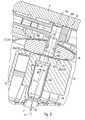
- the positioning device 19 is formed so that the control disc 18 from the offset position shown in FIGS. 1 and 3 can be mounted in an offset position shown in FIG. 2, in which it is rotated about the guide central axis 22 by 180 °, and vice versa.
- the conversion of the control disk 18 into the positions shown in FIGS. 1 and 2 leads to a lateral offset of the control disk 18 and the cylinder block 12 guided thereon, this offset being twice as large as the offset a given by the offset angle W2.
- the axial piston machine 1 described so far can thus be mounted by mounting the control disk 18 in a specific mounting position or by remounting the control disk 18 in 180 ° rotated positions. In these positions of the control disk 18, the axial piston machine 1 is adjustable to two different throughput volumes and adjustable in one stage.
- control disk 18 in addition to the above-described positions in a parallel to the oblique axis E extending pivot guide 31 laterally pivoted and lockable, wherein the pivot guide 31 is curved about the intersection 14 of the longitudinal central axes 11, 13.
- an adjusting device 32 is provided by means of which the control disk 18 in the pivoting guide 31 in the oblique axis plane E back and forth between a minimum position, for. B. with a swivel angle of 0 ° and a maximum position, z. B. with a swivel angle of 26 °, continuously adjustable and lockable in the respective pivot position.
- the pivot guide 31 is formed by a guide groove 31a in the housing interior 4 facing wall of the connecting part 5, wherein the base of the guide groove 31a is formed by the contact surface 19d and concavely curved around the intersection 14 and a curved guide and contact surface 19d forms, on which the control disk 18 with its corresponding convexly curved contact surface 18a is slidably applied.
- the adjusting device 32 integrated into the connector part 5 and z. B. formed by an adjusting slide 32a, which is hydraulically transversely to the guide central axis 22 and in the oblique axis plane E in a slide guide back and forth selectively displaced and lockable in the respective setting.
- the connecting part 5 is arranged obliquely with respect to the central axis 11 in the oblique axis plane and closes with the Central axis 11 an acute angle W3, which corresponds to half the angle of the pivot angle range and in the embodiment is about 16 °.
- W3 16 ° for both exemplary adjustment ranges 0-26 ° and 6-32 °.
- the arranged on the connecting part 5 positioning 19a is attached in the embodiment of the adjusting slide 32a and with this in a corresponding space 34 and slot back and forth displaceable, wherein the control disk 18 is moved by the operative connection of the positioning elements 19a, 19b.
- the peg-shaped positioning 19a immersed with a circularly rounded positioning 19e into the recess forming the Gegenpositiontechnisch 19f in the control disk 18 a.
- a continuously variable axial piston engine 1 embodiment of the invention allows either a reduction or increase in the throughput volume of the axial piston or a targeted from the outset setting the axial piston machine by a corresponding Ummontage or initial assembly.
- a particular advantage of the embodiment according to the invention is the fact that the embodiment of the invention is limited to the formation of the control disk and therefore the embodiment of the invention is suitable for retrofitting the piston engine without the other parts must be changed. So can be z. B. by a corresponding offset of the control disk of the adjustment of the adjustment by the offset size increase, without the need for a corresponding increase in the adjustment itself. This becomes clear when one considers that in an adjustment with an adjustment range of z. B. about 0 to 26 ° the According to the invention configuration in a position of the control disc this adjustment area maintains and leads in the other position to an adjustment, which is increased by the offset of the control disc, but ends by the offset dimension before the 0-point of the adjustment. Even if the axial piston machine is mounted from the outset only with one of the two pivoting angle ranges, the two pivoting angle ranges can be realized with a high proportion of identical parts.
- stops A1, A2 which are adjustable and can be integrated as limiting stops for the adjusting slide 32a in the connecting part 5.
- a minimum stop A1 and a maximum stop A2 each formed by an adjusting screw 35, which passes through the peripheral wall of the housing 2 in a threaded hole 36 approximately in the oblique axis plane E, projects into the housing interior 4 and from the outside by a to a rotary control member, z. B. a slot 37, vulnerable rotary tool is rotatable and lockable, z. B. by means of a lock nut 38th
- the control disk 18 is positioned immovably in each pivot position with respect to the cylinder block 12 in the pivot plane E.
- a positioning device 41 is effective between the control disk 18 and the cylinder block 12, which positions these two parts immovably in the pivoting plane E together.
- This positioning is effected due to the convex shape in the pivoting plane E of the control disk 18 and concave shape of the cylinder block 12. Therefore, the control disc 18 is able to take the cylinder block 12 with its displacement in the pivoting plane E, wherein the positioning device 4i is effective as a driving device.
- the guide member 21 thereby enables the rotation of the cylinder block 12 in the positioning.
- This positioning device 41 is due to the relatively small arc shape of the guide surfaces 23a, 23b prone to between the control disk 18 and the cylinder block 12 effective clamping effects.
- the positioning device 41 is formed by an additional between the control disk 18 and the cylinder block 12 effective journal connection with a positioning pin 42 which fits respectively in Positionieraus strictly traditions 42 a, 42 b in the control disk 18 and the cylinder block 12 and the Fugue 31b interspersed in between.
- the journal portions 42c, 42d of the locating peg 42 engaging in the locating recesses 42a, 42b are offset from each other by the offset amount a and the angle W2, respectively, and one or both of these journal joints is in the positions rotated by 180 ° the control disk 18 can be mounted.
- the positioning recesses 42a, 42b and the pin sections 42c, 42d preferably have a round cross section.
- the positioning pin 42 is mounted non-rotatably in the control disk 18 with respect to the control disk 18.
- the positioning pin 42 may have obliquely extending side sections, which preferably converge convexly or concavely into the journal sections 42c, 42d, as shown in the drawing.
- the Positionieraus strictlyung 42b forms a pivot bearing 40 for the cylinder block 12. It may be a rolling or sliding bearing, which may have a attached to one of the pivot bearing parts sliding bush 12a.
- the positioning recess 19b is arranged in the journal section 42c, wherein it is adapted with respect to its cross-sectional shape and size to the cross-sectional size and shape of the positioning element 19a and can be formed by a blind hole which is open on the front side.
- the positioning recess 19b is preferably formed by a longitudinal channel and open to a guide hole 15a receiving a central guide pin 16a. As a result, the lubrication of the positioning elements 19a, 19b is improved.
- the positioning elements 19a, 19b may be formed as in the embodiment of FIG. 3, namely with a waist 19h on the positioning head 19e and a recess extension 19i on the housing or connecting part 5 facing hole edge to increase the available pivoting range.
- a sliding layer 44 of slippery and / or wear-resistant material disposed between the control disk 18 and the cylinder block 12 may be formed by a disk which may be fixed to the control disk 18, e.g. by soldering, welding or gluing.
- a hole 44a in the disk penetrated by the locating pin 42 is so large that the transition area 42g has clearance therein in the two offset positions.
- the guide surfaces 23a, 23b in contrast to the above-described embodiment, flat surfaces, but they can also be spherical section-shaped concave or convex, as is the case in the above-described embodiment.
- the positioning recess 42b and the pin portion 42d are preferably arranged coaxially to the longitudinal central axis 13 of the cylinder block 12.
- the positioning recess 42a and the positioning pin 42c and the Positioning recess 19b may be offset in parallel with respect to the longitudinal central axis 13 and the offset a.
- the positioning recess 42a, the pin section 42c located therein and the positioning recess 19b are arranged rotated relative to the longitudinal center axis 13 by the angle W2 relative to one another.
- the remounting of the control disk 18 can take place with removed housing cover or connector 5 characterized in that the control disk 18 is lifted from the journal portion 42c, rotated about 180 ° about the central axis 13 and replaced, or that the control disk 18 with the positioning pin 42 from the Positioning recess 42 b excavated, rotated about 180 ° about the central axis 13 and is inserted back into the positioning recess 42 b. If possible, the conversion can also take place in that the positioning pin 42 is rotated by 180 ° in the PositionierausEnglishung 42b.
Landscapes
- Engineering & Computer Science (AREA)
- Mechanical Engineering (AREA)
- General Engineering & Computer Science (AREA)
- Reciprocating Pumps (AREA)
Claims (19)
- Machine à pistons axiaux (1), comprenant un boîtier (2), dans lequel sont agencés un plateau moteur (7) et un bloc à cylindres (12) agencé axialement à côté de celui-ci, lesquels sont montés en rotation l'un par rapport à l'autre autour d'axes médians longitudinaux (11, 13) qui s'étendent en oblique l'un par rapport à l'autre d'un angle (W1) dans un plan d'axe oblique (E),
dans laquelle, dans le bloc à cylindres (12) sont ménagés plusieurs perçages à pistons (15) dans lesquels sont guidés des pistons (16) avec possibilité de translation en va-et-vient, dont les extrémités de pistons tournées vers le plateau moteur (7) sont soutenues sur le plateau moteur (7) avec possibilité de basculement sur tous les côtés,
dans laquelle, sur le côté frontal, opposé au côté tourné vers le plateau moteur (7), du bloc à cylindres (12) est agencé un disque de commande (18) qui est soutenu sur le boîtier (2) par un premier dispositif de positionnement (19) doté d'éléments de positionnement (19a, 19b) qui coopèrent en coopération de formes, et qui comprend, sur son côté tourné vers le bloc à cylindres (12), un élément de guidage (21) doté d'un axe médian de guidage (22) s'étendant coaxialement à l'axe médian longitudinal (13) du bloc à cylindres (12),
caractérisée en ce que :parmi les éléments de positionnement (19a, 19b), l'élément de positionnement (19b) agencé sur le disque de commande (18) est décalé transversalement à l'axe médian de guidage (22) de l'élément de guidage (21) dans le plan d'axe oblique (E) et le disque de commande (18) peut être monté dans une autre position, tournée d'environ 180° autour de l'axe médian de guidage (22) de l'élément de guidage (21), dans laquelle les éléments de positionnement (19a, 19b) sont également en coopération. - Machine à pistons axiaux selon la revendication 1,
caractérisée en ce que
le premier dispositif de positionnement (19) comporte un guide de basculement (31) incurvé autour du point d'intersection (14) entre les axes médians longitudinaux (11, 13) du plateau moteur (7) et du tambour à cylindres (12), guide dans lequel le disque de commande (18) est déplaçable dans le plan d'axe oblique (E) au moyen d'un dispositif de déplacement (32) et susceptible d'être immobilisé dans la position déplacée respective. - Machine à pistons axiaux selon la revendication 1 ou 2,
caractérisée en ce que
l'élément de positionnement (19b) est décalé, par rapport à l'axe médian de guidage (22), d'un angle de décalage (W2) qui est inférieur à environ 10°. - Machine à pistons axiaux selon la revendication 3,
caractérisée en ce que
l'angle de décalage (W2) s'élève à environ 3°. - Machine à pistons axiaux selon l'une des revendications précédentes,
caractérisée en ce que
l'élément de guidage (21) comporte une surface de guidage (23a) incurvée à symétrie de révolution autour de l'axe médian de guidage (22), qui est de préférence une partie en relief du disque de commande (18) ou qui est plane, et en ce que la surface frontale, tournée vers le disque de commande (18), du bloc à cylindres (12), est adaptée à la forme de la surface de guidage (23a). - Machine à pistons axiaux selon l'une des revendications précédentes,
caractérisée en ce que
l'élément de positionnement (19b) agencé sur le disque de commande (18) est un évidement dans lequel s'engage un tenon de déplacement à titre de second élément de positionnement (19a). - Machine à pistons axiaux selon l'une des revendications 1 à 6,
caractérisée en ce que
le bloc à cylindres (12) est soutenu contre le disque de commande (18) par l'élément de guidage (21) transversalement à son axe médian longitudinal (13). - Machine à pistons axiaux selon l'une des revendications précédentes,
caractérisée en ce que
le bloc à cylindres (12) est positionné en coopération de formes par un second dispositif de positionnement (41) à l'encontre d'un déplacement relatif dans le plan d'axe oblique (E). - Machine à pistons axiaux selon la revendication 8,
caractérisée en ce que
le second dispositif de positionnement (41) est formé par un tenon de positionnement (42) qui est logé par un tronçon de tenon (42c) dans un évidement de positionnement (42a) dans le disque de commande (18), et qui est logé par un tenon de positionnement (42d), décalé dans le plan d'axe oblique (32) à raison du décalage (a), dans un évidement de positionnement (42b) du bloc à cylindres (12). - Machine à pistons axiaux selon la revendication 9,
caractérisée en ce que
le tronçon de tenon (42d) logé dans le bloc à cylindres (12) est monté au moyen d'un palier de rotation (40) avec possibilité de rotation dans le bloc à cylindres (12). - Machine à pistons axiaux selon la revendication 9 ou 10,
caractérisée en ce que
le tronçon de tenon (42c) logé dans le disque de commande (18) forme un élément de positionnement pour le premier dispositif de positionnement (19). - Machine à pistons axiaux selon la revendication 11,
caractérisée en ce que
l'élément de positionnement est formé par un évidement de positionnement (19b) ouvert du côté frontal. - Machine à pistons axiaux selon l'une des revendications 9 à 12,
caractérisée en ce que
entre le disque de commande (18) et le bloc à cylindres (12) est agencé un disque (44) avec un trou (44a) pour le tenon de positionnement (42), trou qui est de préférence suffisamment grand pour que, dans les positions décalées du disque de commande (18), une zone de transition (42g), s'étendant de préférence en oblique, du tenon de positionnement (42), dispose d'un espace libre dans le trou (44a). - Machine à pistons axiaux selon l'une des revendications 9 à 13,
caractérisée en ce que
le tenon de positionnement (42) présente un trou traversant orienté longitudinalement, qui débouche de préférence dans l'évidement de positionnement (19b). - Disque de commande (18) pour une machine à pistons axiaux (1) qui comprend un boîtier (2) dans lequel sont agencés un plateau moteur (7) et un bloc à cylindres (12) agencé axialement à côté de celui-ci, et doté de pistons déplaçables axialement dans celui-ci, le plateau moteur et le bloc cylindres étant montés en rotation l'un par rapport à l'autre autour d'axes médians longitudinaux (11, 13) qui s'étendent en oblique l'un par rapport à l'autre d'un angle (W1) dans un plan d'axe oblique (E),
ledit disque de commande (18) comprenant :- un élément de guidage (21) agencé sur un premier côté du disque de commande (18) et présentant un axe médian de guidage (22) qui s'étend transversalement au disque de commande (18) et dans sa zone médiane,- une surface de guidage de basculement (18a) sur le second côté, opposé au premier côté, du disque de commande (18), ladite surface de guidage de basculement (18a) étant incurvée de manière convexe en forme d'arc de cercle autour d'un point d'intersection (14) situé sur l'axe médian de guidage (22) et parallèlement à un plan d'axe oblique (E) qui contient l'axe médian de guidage (22),- et un élément de positionnement (19b) sur le disque de commande (18) pour positionner le disque de commande (18) sur le boîtier (2),caractérisé en ce que
l'élément de positionnement (19b) sur le disque de commande (18) est décalé dans le plan d'axe oblique (E) transversalement à l'axe médian de guidage (22) du disque de commande (18). - Disque de commande selon la revendication 15,
caractérisé en ce que l'élément de positionnement (19b) est décalé par rapport à l'axe médian de guidage (22) d'un angle de décalage (W2) qui est inférieur à environ 10°. - Disque de commande selon la revendication 16,
caractérisé en ce que
l'angle de décalage (W2) s'élève à environ 3°. - Disque de commande selon l'une des revendications 15 à 17,
caractérisé en ce que
l'élément de guidage (21) présente une surface de guidage (23a) incurvée à symétrie de révolution autour de l'axe médian de guidage (22), qui est de préférence une partie en relief du disque de commande (18). - Disque de commande selon l'une des revendications 15 à 18,
caractérisé en ce que
l'élément de positionnement (19b) agencé sur le disque de commande (18) est un évidement dans lequel peut s'engager un tenon de déplacement (19a).
Applications Claiming Priority (3)
| Application Number | Priority Date | Filing Date | Title |
|---|---|---|---|
| DE10326059 | 2003-06-11 | ||
| DE10347086A DE10347086A1 (de) | 2003-06-11 | 2003-10-10 | Axialkolbenmaschine mit versetztem Positionierelement und Steuerscheibe für eine solche Axialkolbenmaschine |
| PCT/EP2004/003250 WO2004109107A1 (fr) | 2003-06-11 | 2004-03-26 | Machine a pistons axiaux comportant un element de positionnement decale et came de commande pour une telle machine a pistons axiaux |
Publications (2)
| Publication Number | Publication Date |
|---|---|
| EP1631744A1 EP1631744A1 (fr) | 2006-03-08 |
| EP1631744B1 true EP1631744B1 (fr) | 2007-02-28 |
Family
ID=33512389
Family Applications (1)
| Application Number | Title | Priority Date | Filing Date |
|---|---|---|---|
| EP04723575A Expired - Lifetime EP1631744B1 (fr) | 2003-06-11 | 2004-03-26 | Machine a pistons axiaux comportant un element de positionnement decale et came de commande pour une telle machine a pistons axiaux |
Country Status (4)
| Country | Link |
|---|---|
| US (1) | US7363849B2 (fr) |
| EP (1) | EP1631744B1 (fr) |
| DE (1) | DE502004003059D1 (fr) |
| WO (1) | WO2004109107A1 (fr) |
Families Citing this family (9)
| Publication number | Priority date | Publication date | Assignee | Title |
|---|---|---|---|---|
| WO2007060822A1 (fr) * | 2005-11-24 | 2007-05-31 | Komatsu Ltd. | Pompe/moteur a deplacement variable de type a arbre incline |
| JP5425722B2 (ja) * | 2010-06-23 | 2014-02-26 | 日立建機株式会社 | 斜軸式液圧回転機 |
| DE102014104951A1 (de) | 2014-04-08 | 2015-10-08 | Linde Hydraulics Gmbh & Co. Kg | Axialkolbenmaschine in Schrägachsenbauweise |
| DE102015107343A1 (de) * | 2015-05-11 | 2016-11-17 | Linde Hydraulics Gmbh & Co. Kg | Hydrostatische Axialkolbenmaschine in Schrägachsenbauweise |
| EP3168469B1 (fr) | 2015-11-11 | 2019-06-05 | Linde Hydraulics GmbH & Co. KG | Hydrostatische axialkolbenmaschine in schrägachsenbauweise |
| DE102016100920A1 (de) | 2015-11-11 | 2017-05-11 | Linde Hydraulics Gmbh & Co. Kg | Hydrostatische Axialkolbenmaschine in Schrägachsenbauweise |
| CN112459981A (zh) * | 2020-11-29 | 2021-03-09 | 江苏可奈力机械制造有限公司 | 一种滑道斜轴变量高压柱塞泵 |
| CN115788592A (zh) * | 2022-12-09 | 2023-03-14 | 浙江赛克思液压有限公司 | 用于斜轴式变量马达的中心柱塞和新型斜轴式柱塞变量马达 |
| US12372074B1 (en) * | 2024-07-23 | 2025-07-29 | Hamilton Sundstrand Corporation | Piston retainer plate |
Family Cites Families (7)
| Publication number | Priority date | Publication date | Assignee | Title |
|---|---|---|---|---|
| US2968286A (en) * | 1956-05-29 | 1961-01-17 | Reiners Walter | Hydraulic axial-piston machine |
| DE19649195C1 (de) * | 1996-11-27 | 1998-01-08 | Brueninghaus Hydromatik Gmbh | Axialkolbenmaschine mit Lagerspülung |
| DE19833711A1 (de) * | 1998-07-27 | 2000-02-10 | Brueninghaus Hydromatik Gmbh | Hydrostatische Axialkolbenmaschine mit einer Nachführvorrichtung für eine Zwischenscheibe |
| DE19842029B4 (de) * | 1998-09-14 | 2005-02-17 | Sauer-Sundstrand Gmbh & Co. | Verstellung von hydrostatischen Axialkolbenmaschinen mittels Schrittmotor |
| DE19857366C2 (de) * | 1998-12-11 | 2000-10-19 | Brueninghaus Hydromatik Gmbh | Axialkolbenmaschine |
| DE10030147C1 (de) * | 2000-06-20 | 2002-06-06 | Brueninghaus Hydromatik Gmbh | Axialkolbenmaschine |
| DE10119236C1 (de) | 2001-04-19 | 2002-12-12 | Brueninghaus Hydromatik Gmbh | Axialkolbenmaschine in Schrägachsen-Bauweise, mit einem Schwenkwinkel-Sensor |
-
2004
- 2004-03-26 DE DE502004003059T patent/DE502004003059D1/de not_active Expired - Lifetime
- 2004-03-26 WO PCT/EP2004/003250 patent/WO2004109107A1/fr not_active Ceased
- 2004-03-26 US US10/550,292 patent/US7363849B2/en not_active Expired - Fee Related
- 2004-03-26 EP EP04723575A patent/EP1631744B1/fr not_active Expired - Lifetime
Also Published As
| Publication number | Publication date |
|---|---|
| US7363849B2 (en) | 2008-04-29 |
| US20060180016A1 (en) | 2006-08-17 |
| WO2004109107A1 (fr) | 2004-12-16 |
| EP1631744A1 (fr) | 2006-03-08 |
| DE502004003059D1 (de) | 2007-04-12 |
Similar Documents
| Publication | Publication Date | Title |
|---|---|---|
| DE19937560B4 (de) | Orbital hin- und hergehende Säge | |
| EP0372376B1 (fr) | Mécanisme d'entraînement oscillant | |
| DE3545200C2 (fr) | ||
| DE2533498C2 (de) | Anordnung und Ausgestaltung des Schwenkflügelmotors an einer hydraulischen Axialkolbenmaschine | |
| DE3942189C1 (fr) | ||
| DE69604972T2 (de) | Taumelscheibenkompressor mit veränderlicher Förderleistung und mit einer verbesserten Gelenkvorrichtung zur Neigungsunterstützung einer Taumelscheibe | |
| DE69301254T2 (de) | Hydraulische Kolbenpumpe mit Einlassventilen | |
| DE69026841T2 (de) | Schiefscheibenkolbenpumpe oder -motor | |
| EP1631744B1 (fr) | Machine a pistons axiaux comportant un element de positionnement decale et came de commande pour une telle machine a pistons axiaux | |
| DE69524783T2 (de) | Neigungswinkelstellvorrichtung für eine taumelscheibenpumpe | |
| DE2115350C3 (de) | Einrichtung zur Geräuschminderung an einer schlitzgesteuerten Axialkolbenpumpe | |
| DE4400911A1 (de) | Drehgelenkbeschlag für einen Fahrzeugsitz mit einem oberen und einem unteren Beschlagteil und einem dazwischen angeordneten Taumelgetriebe | |
| DE19755386C2 (de) | Hydrostatische Maschine mit einer drehbar gelagerten Zylindertrommel und einer einstellbaren Schwenkscheibe | |
| EP0841447A1 (fr) | Gâche automatique avec une pièce de blocage réglable et pivotante | |
| EP0525507B1 (fr) | Dispositif de réglage d'un actionneur pour régler la cylindrée d'une machine hydrostatique | |
| DE10347086A1 (de) | Axialkolbenmaschine mit versetztem Positionierelement und Steuerscheibe für eine solche Axialkolbenmaschine | |
| EP1008748B1 (fr) | Machine à pistons axiaux | |
| EP0309762B1 (fr) | Machine à piston axial réglable du type à plateau incliné | |
| DE3728448C2 (fr) | ||
| DE2825473C2 (de) | Taumelscheibenpumpe mit zwei Drehrichtungen | |
| EP1251270B1 (fr) | Pompe à pistons axiaux à capacité variable avec détecteur d'inclination | |
| DE19833711A1 (de) | Hydrostatische Axialkolbenmaschine mit einer Nachführvorrichtung für eine Zwischenscheibe | |
| DE19527649A1 (de) | Axialkolbenmaschine | |
| DE10304157A1 (de) | Pendelhubschalter | |
| DE102005036853A1 (de) | Axialkolbenmaschine mit einem länglichen Führungselement für ein Käfigsegment |
Legal Events
| Date | Code | Title | Description |
|---|---|---|---|
| PUAI | Public reference made under article 153(3) epc to a published international application that has entered the european phase |
Free format text: ORIGINAL CODE: 0009012 |
|
| 17P | Request for examination filed |
Effective date: 20050331 |
|
| AK | Designated contracting states |
Kind code of ref document: A1 Designated state(s): DE FR GB IT SE SK |
|
| DAX | Request for extension of the european patent (deleted) | ||
| RBV | Designated contracting states (corrected) |
Designated state(s): DE FR GB IT SE SK |
|
| GRAP | Despatch of communication of intention to grant a patent |
Free format text: ORIGINAL CODE: EPIDOSNIGR1 |
|
| GRAS | Grant fee paid |
Free format text: ORIGINAL CODE: EPIDOSNIGR3 |
|
| GRAA | (expected) grant |
Free format text: ORIGINAL CODE: 0009210 |
|
| AK | Designated contracting states |
Kind code of ref document: B1 Designated state(s): DE FR GB IT SE SK |
|
| REG | Reference to a national code |
Ref country code: GB Ref legal event code: FG4D Free format text: NOT ENGLISH |
|
| GBT | Gb: translation of ep patent filed (gb section 77(6)(a)/1977) |
Effective date: 20070228 |
|
| REF | Corresponds to: |
Ref document number: 502004003059 Country of ref document: DE Date of ref document: 20070412 Kind code of ref document: P |
|
| REG | Reference to a national code |
Ref country code: SE Ref legal event code: TRGR |
|
| ET | Fr: translation filed | ||
| PLBE | No opposition filed within time limit |
Free format text: ORIGINAL CODE: 0009261 |
|
| STAA | Information on the status of an ep patent application or granted ep patent |
Free format text: STATUS: NO OPPOSITION FILED WITHIN TIME LIMIT |
|
| 26N | No opposition filed |
Effective date: 20071129 |
|
| PGFP | Annual fee paid to national office [announced via postgrant information from national office to epo] |
Ref country code: SE Payment date: 20091222 Year of fee payment: 7 |
|
| PGFP | Annual fee paid to national office [announced via postgrant information from national office to epo] |
Ref country code: FR Payment date: 20100331 Year of fee payment: 7 Ref country code: SK Payment date: 20100324 Year of fee payment: 7 |
|
| PGFP | Annual fee paid to national office [announced via postgrant information from national office to epo] |
Ref country code: GB Payment date: 20100324 Year of fee payment: 7 |
|
| REG | Reference to a national code |
Ref country code: SE Ref legal event code: EUG |
|
| GBPC | Gb: european patent ceased through non-payment of renewal fee |
Effective date: 20110326 |
|
| REG | Reference to a national code |
Ref country code: SK Ref legal event code: MM4A Ref document number: E 1833 Country of ref document: SK Effective date: 20110326 |
|
| REG | Reference to a national code |
Ref country code: FR Ref legal event code: ST Effective date: 20111130 |
|
| PG25 | Lapsed in a contracting state [announced via postgrant information from national office to epo] |
Ref country code: FR Free format text: LAPSE BECAUSE OF NON-PAYMENT OF DUE FEES Effective date: 20110331 |
|
| PG25 | Lapsed in a contracting state [announced via postgrant information from national office to epo] |
Ref country code: SK Free format text: LAPSE BECAUSE OF NON-PAYMENT OF DUE FEES Effective date: 20110326 Ref country code: GB Free format text: LAPSE BECAUSE OF NON-PAYMENT OF DUE FEES Effective date: 20110326 |
|
| PGFP | Annual fee paid to national office [announced via postgrant information from national office to epo] |
Ref country code: IT Payment date: 20120327 Year of fee payment: 9 |
|
| PG25 | Lapsed in a contracting state [announced via postgrant information from national office to epo] |
Ref country code: SE Free format text: LAPSE BECAUSE OF NON-PAYMENT OF DUE FEES Effective date: 20110327 |
|
| PG25 | Lapsed in a contracting state [announced via postgrant information from national office to epo] |
Ref country code: IT Free format text: LAPSE BECAUSE OF NON-PAYMENT OF DUE FEES Effective date: 20140326 |
|
| PGFP | Annual fee paid to national office [announced via postgrant information from national office to epo] |
Ref country code: DE Payment date: 20150521 Year of fee payment: 12 |
|
| REG | Reference to a national code |
Ref country code: DE Ref legal event code: R119 Ref document number: 502004003059 Country of ref document: DE |
|
| PG25 | Lapsed in a contracting state [announced via postgrant information from national office to epo] |
Ref country code: DE Free format text: LAPSE BECAUSE OF NON-PAYMENT OF DUE FEES Effective date: 20161001 |