EP1632111B1 - Vorrichtung und verfahren für den betrieb von stromabhängigen elektronischen geräten - Google Patents
Vorrichtung und verfahren für den betrieb von stromabhängigen elektronischen geräten Download PDFInfo
- Publication number
- EP1632111B1 EP1632111B1 EP04727942A EP04727942A EP1632111B1 EP 1632111 B1 EP1632111 B1 EP 1632111B1 EP 04727942 A EP04727942 A EP 04727942A EP 04727942 A EP04727942 A EP 04727942A EP 1632111 B1 EP1632111 B1 EP 1632111B1
- Authority
- EP
- European Patent Office
- Prior art keywords
- current
- electronic devices
- voltage output
- voltage
- regulator
- Prior art date
- Legal status (The legal status is an assumption and is not a legal conclusion. Google has not performed a legal analysis and makes no representation as to the accuracy of the status listed.)
- Expired - Lifetime
Links
- 238000000034 method Methods 0.000 title claims description 8
- 230000001419 dependent effect Effects 0.000 title 1
- 238000006243 chemical reaction Methods 0.000 claims abstract description 5
- 238000005259 measurement Methods 0.000 claims description 2
- 239000004020 conductor Substances 0.000 description 2
- 208000032365 Electromagnetic interference Diseases 0.000 description 1
- 239000003086 colorant Substances 0.000 description 1
- 238000010586 diagram Methods 0.000 description 1
- 230000007774 longterm Effects 0.000 description 1
- 238000012986 modification Methods 0.000 description 1
- 230000004048 modification Effects 0.000 description 1
- 238000001228 spectrum Methods 0.000 description 1
Images
Classifications
-
- H—ELECTRICITY
- H05—ELECTRIC TECHNIQUES NOT OTHERWISE PROVIDED FOR
- H05B—ELECTRIC HEATING; ELECTRIC LIGHT SOURCES NOT OTHERWISE PROVIDED FOR; CIRCUIT ARRANGEMENTS FOR ELECTRIC LIGHT SOURCES, IN GENERAL
- H05B45/00—Circuit arrangements for operating light-emitting diodes [LED]
- H05B45/10—Controlling the intensity of the light
-
- H—ELECTRICITY
- H05—ELECTRIC TECHNIQUES NOT OTHERWISE PROVIDED FOR
- H05B—ELECTRIC HEATING; ELECTRIC LIGHT SOURCES NOT OTHERWISE PROVIDED FOR; CIRCUIT ARRANGEMENTS FOR ELECTRIC LIGHT SOURCES, IN GENERAL
- H05B45/00—Circuit arrangements for operating light-emitting diodes [LED]
- H05B45/30—Driver circuits
- H05B45/345—Current stabilisation; Maintaining constant current
Definitions
- the present invention relates to an apparatus and method for operating one or more electronic devices which require a constant given current.
- the invention concerns operating a number of current devices such as light emitting diodes (LEDs) mounted on conductive strip to provide an elongate lighting strip.
- LEDs light emitting diodes
- Such lighting strips are well-known for example to mark the way to emergency exits on aircraft. They comprise a plurality of LEDs mounted at intervals along a conductive strip encased in plastic. LEDs, in common with a number of other electrical devices, are current devices, that is they rely on a constant current to operate, rather than a constant voltage. The life and brightness of a LED can be maximised by accurately controlling the current.
- Known lighting strips have a driver apparatus which is designed to operate a given number and a particular type of LED. If the driver is used on a strip having a different number of LEDs or a different type of LED, then the drive apparatus must be completely reset which is a time-consuming, awkward and inefficient process.
- An example of such an apparatus is given is EP 0 480 650-A1.
- the present invention provides an apparatus for operating one or more electronic devices requiring a given current, comprising a regulator device providing a voltage output, and a feedback loop having a reference device connected to the voltage output and requiring the same current as the electronic devices, a measuring and conversion device operable to measure the current through the reference device and convert it to a voltage value and return it to the regulator device, wherein the regulator device is operable to adjust the output voltage in response to the voltage value until the measured current is equal to the given current required, wherein the electronic devices comprise light emitting diodes mounted on a conductive strip having a plurality of conductive elements, and wherein the electronic devices are parallel connected and polarity sensitive, and the regulator is connected to a three-phase bridge and a micro-controller operable to control the sequence in which the LEDs on the conductive strip are operated. The three phase bridge operates the conductive elements in the strip.
- a reference device of the same type as the electronic device that is to be operated allows the regulator automatically to adjusted to produce an absolute voltage of the appropriate level to drive the remaining devices. In this way, the apparatus is able to produce the correct voltage, automatically compensating for both short and long term drift, for any type and number of electronic devices being used.
- the measurement and conversion device consists of a resistor and a current monitor.
- the regulator comprises a steady state DC device.
- the present invention also provides a method for operating one or more electronic devices requiring a given current, comprising the steps of providing a voltage output, supplying the voltage output to a reference device requiring the same current as the electronic devices, measuring the current in the reference device, converting the measured current to a voltage value and adjusting the voltage output in response to the voltage value until the measured current in the reference device is equal to the given current required by the electronic devices, the method further comprising the step of initially providing a voltage output sufficient to produce a current lower than the given current and gradually increasing the voltage output until the given current is obtained in the reference device.
- a feature of the present invention is that an electronic device of the same type as those to be operated is incorporated into a feedback loop of the apparatus.
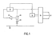
- a regulator device 10 is connected to the electronic devices to be driven.
- the regulator 10 is preferably, but not exclusively, a steady state DC device for accuracy.
- the electronic devices are LEDs (not shown) mounted on a conductive strip having three conductors 12.
- a three-phase bridge 14 is connected between the regulator device 10 and the conductors 12.
- the regulator 10 is also connected to a micro controller 16, itself connected to the three-phase bridge 14, for example to control the sequence of operation of the LEDs in the conductive strip.
- the regulator 10 is also provided with a feedback loop.
- the voltage output from the regulator 10 also passes through a current measuring device such as a resistor 18 and a reference LED 20 of the same type as those in the strip which are to be driven.
- the resistor 18 is also connected to a current monitor device 22. Together the resistor 18 and the current monitor 22 act to measure the current passing through the reference LED 20 and to convert it to a voltage. This is passed back to the regulator 10. Since the desired current for the LEDs in the conductive strip is known from the outset and the reference LED 20 is of the same type as the LEDs to be operated, this feedback loop allows the voltage output from the regulator 10 to be adjusted to the appropriate level so that the desired current is achieved.
- the regulator 10 will initially be set to produce a voltage output which is lower than that required to provide the desired current.
- the current through the reference LED 20 is then measured as the voltage output is gradually increased until the desired current through the reference LED 20 is achieved. At this point, the voltage output from the regulator 10 will be at the right level to operate the LEDs in the lighting strip in an optimum manner.
- Another important feature of the lighting strip of the preferred embodiment of the present invention is that it is directly driven by a controlled voltage source thus removing the requirement for resistors within the lighting strip itself. Removal of the resistors from the lighting strip reduces the capacity for the lighting strip to heat up and consequently reduces the power consumption of the lighting strip.
- Electro Magnetic Compatability can significantly reduce such interference by providing a standing DC voltage just below the threshold level required to operate the LEDs and superimposing small pulses which raise the voltage above the threshold in order to switch the LEDs on.
- the switching voltage is thus a fraction of the full operating voltage then and the electro magnetic interference can be significantly reduced.
- the voltage pulses can have soft edges.
- the regulator 10 may be provided with separate feedback loops with a reference LED of each colour and the micro controller may be used to control which LEDs are to operate at a given time.
- the present invention is not restricted to use with conductive strips having LEDs, or indeed to conductive strips having devices which emit visible light. The invention is equally applicable to use with devices producing other wavelengths in the electromagnetic spectrum, whether producing visible light or not.
- the invention provides a simple and efficient manner in which to operate current devices, which is easily adaptable to operating different types and numbers of devices.
Landscapes
- Circuit Arrangement For Electric Light Sources In General (AREA)
- Control Of El Displays (AREA)
- Led Devices (AREA)
- Control Of Electric Motors In General (AREA)
Claims (4)
- Gerät zum Betreiben von elektronischen, einen gegebenen Strom benötigenden Vorrichtungen, umfassend:eine Regelvorrichtung (10), welche eine Ausgangsspannung bereitstellt zur Verwendung durch die elektronischen Vorrichtungen, und einen Regelkreis mit einer Referenzvorrichtung (20), welche mit der Ausgangsspannung verbunden ist und den gleichen Strom benötigt wie die elektronischen Vorrichtungen, eine Mess- und Wandlervorrichtung, welche betreibbar ist, um den Strom durch die Referenzvorrichtung (20) zu messen und ihn in einen Spannungswert umzuwandeln und ihn an die Regelvorrichtung zurückzugeben, wobei die Regelvorrichtung betreibbar ist, um die Ausgangsspannung in Reaktion auf den Spannungswert anzupassen bis der gemessene Strom gleich dem benötigten, gegebenen Strom ist, wobei die elektronischen Vorrichtungen Leuchtdioden umfassen, welche auf einem leitenden Streifen mit mehreren leitenden Elementen (12) angebracht sind, und wobei die elektronischen Vorrichtungen parallel geschaltet und polaritätsempfindlich sind, undwobei die Regelvorrichtung mit einer Drei-Phasen-Brücke (14) und einem Mikrocontroller (16) verbunden ist, welcher betreibbar ist, um die Reihenfolge, in der die LED auf dem leitenden Streifen betrieben werden sollen, zu steuern.
- Gerät nach Anspruch 1, wobei die Mess- und Wandlervorrichtung einen Widerstand (18) und ein Stromüberwachungsgerät (22) umfasst.
- Gerät nach Anspruch 1 oder 2, wobei die Regelvorrichtung (10) eine Stationärzustands-Gleichstromvorrichtung umfasst.
- Verfahren zum Betreiben von elektronischen, einen gegebenen Strom benötigenden Vorrichtungen, umfassend die Schritte:Bereitstellen einer Ausgangsspannung,Zuführen der Ausgangsspannung zu einer Referenzvorrichtung (20), welche den gleichen Strom benötigt wie die elektronischen Vorrichtungen, Messen des Stroms in der Referenzvorrichtung (20),Umwandeln des gemessenen Stroms in einen Spannungswert, und Anpassen der Ausgangsspannung in Reaktion auf den Spannungswert bis der gemessene Strom in der Referenzvorrichtung (20) gleich dem gegebenen, von den elektronischen Vorrichtungen benötigten Strom ist, wobei die elektronischen Vorrichtungen Leuchtdioden umfassen, welche auf einem leitenden Streifen mit mehreren leitenden Elementen (12) angebracht sind, wobei das Verfahren ferner den Schritt umfasst, anfänglich eine Ausgangsspannung bereitzustellen, welche ausreicht, um einen Strom bereitzustellen, der geringer ist als der gegebene Strom, und allmählich die Ausgangsspannung zu vergrößern bis der gemessene Strom in der Referenzvorrichtung (20) gleich dem gegebenen Strom ist,dadurch gekennzeichnet, dass die elektronischen Vorrichtungen parallel geschaltet und polaritätsempfindlich sind, wobei das Verfahren ferner das Steuern der Reihenfolge umfasst, in welcher die Leuchtdioden betrieben werden, unter Verwendung einer Drei-Phasen-Brücke (14) und eines Mikrocontrollers (16).
Applications Claiming Priority (2)
| Application Number | Priority Date | Filing Date | Title |
|---|---|---|---|
| GB0308815A GB2400691B (en) | 2003-04-16 | 2003-04-16 | Apparatus and method for operating current dependent electronic devices |
| PCT/GB2004/001670 WO2004095887A1 (en) | 2003-04-16 | 2004-04-16 | Apparatus and method for operating current dependent electronic devices |
Publications (2)
| Publication Number | Publication Date |
|---|---|
| EP1632111A1 EP1632111A1 (de) | 2006-03-08 |
| EP1632111B1 true EP1632111B1 (de) | 2006-09-06 |
Family
ID=9956905
Family Applications (1)
| Application Number | Title | Priority Date | Filing Date |
|---|---|---|---|
| EP04727942A Expired - Lifetime EP1632111B1 (de) | 2003-04-16 | 2004-04-16 | Vorrichtung und verfahren für den betrieb von stromabhängigen elektronischen geräten |
Country Status (6)
| Country | Link |
|---|---|
| EP (1) | EP1632111B1 (de) |
| AT (1) | ATE339078T1 (de) |
| DE (1) | DE602004002302T2 (de) |
| ES (1) | ES2273249T3 (de) |
| GB (1) | GB2400691B (de) |
| WO (1) | WO2004095887A1 (de) |
Family Cites Families (11)
| Publication number | Priority date | Publication date | Assignee | Title |
|---|---|---|---|---|
| US4271408A (en) * | 1978-10-17 | 1981-06-02 | Stanley Electric Co., Ltd. | Colored-light emitting display |
| GB2106299B (en) * | 1981-09-23 | 1985-06-19 | Smiths Industries Plc | Electroluminescent display devices |
| DE3315785A1 (de) * | 1983-04-30 | 1984-11-08 | Robert Bosch Gmbh, 7000 Stuttgart | Kraftfahrzeugleuchte |
| DE68921020T2 (de) * | 1988-05-20 | 1995-06-29 | Mitsubishi Electric Corp | Integrierte MOS-Schaltung zum Steuern von lichtermittierenden Dioden. |
| US4864216A (en) * | 1989-01-19 | 1989-09-05 | Hewlett-Packard Company | Light emitting diode array current power supply |
| US4952949A (en) * | 1989-11-28 | 1990-08-28 | Hewlett-Packard Company | LED printhead temperature compensation |
| US5099192A (en) * | 1990-10-12 | 1992-03-24 | Hewlett-Packard Company | Light emitting diode array current power supply |
| AU2001229632A1 (en) * | 2000-01-14 | 2001-07-24 | Design Rite Llc | Circuit for driving light-emitting diodes |
| SG111928A1 (en) * | 2001-01-29 | 2005-06-29 | Semiconductor Energy Lab | Light emitting device |
| US6614191B2 (en) * | 2001-02-02 | 2003-09-02 | Hewlett-Packard Company | System and method for illuminating light emitting diodes in a contact image sensor |
| DE10115388A1 (de) * | 2001-03-28 | 2002-10-10 | Patent Treuhand Ges Fuer Elektrische Gluehlampen Mbh | Ansteuerschaltung für ein LED-Array |
-
2003
- 2003-04-16 GB GB0308815A patent/GB2400691B/en not_active Expired - Fee Related
-
2004
- 2004-04-16 ES ES04727942T patent/ES2273249T3/es not_active Expired - Lifetime
- 2004-04-16 EP EP04727942A patent/EP1632111B1/de not_active Expired - Lifetime
- 2004-04-16 WO PCT/GB2004/001670 patent/WO2004095887A1/en not_active Ceased
- 2004-04-16 DE DE602004002302T patent/DE602004002302T2/de not_active Expired - Fee Related
- 2004-04-16 AT AT04727942T patent/ATE339078T1/de not_active IP Right Cessation
Also Published As
| Publication number | Publication date |
|---|---|
| DE602004002302D1 (de) | 2006-10-19 |
| DE602004002302T2 (de) | 2007-04-05 |
| WO2004095887A1 (en) | 2004-11-04 |
| EP1632111A1 (de) | 2006-03-08 |
| GB2400691B (en) | 2005-10-26 |
| ATE339078T1 (de) | 2006-09-15 |
| GB0308815D0 (en) | 2003-05-21 |
| ES2273249T3 (es) | 2007-05-01 |
| GB2400691A (en) | 2004-10-20 |
Similar Documents
| Publication | Publication Date | Title |
|---|---|---|
| US9326346B2 (en) | Method and device for remote sensing and control of LED lights | |
| US9013114B2 (en) | Power control system for an illumination system | |
| US10791600B2 (en) | Illumination device control systems and methods | |
| RU2497316C2 (ru) | Устройство возбуждения led | |
| US20140346958A1 (en) | Load Driving Device, and Lighting Apparatus and Liquid Crystal Display Device Using the Same | |
| US20100219764A1 (en) | Led dimming apparatus | |
| US11487310B2 (en) | Load driving device, and lighting apparatus and liquid crystal display device using the same | |
| EP3808156B1 (de) | Überwachungsvorrichtung für eine beleuchtungsanordnung, treiber mit verwendung der überwachungseinrichtung und ansteuerungsverfahren | |
| CN112423430A (zh) | 用于led照明系统的电流分路器 | |
| WO2015097476A2 (en) | A lighting system | |
| CN101894530A (zh) | 驱动电路及其保护方法、发光装置及显示器装置 | |
| EP3192327A1 (de) | Led-dimmerschaltung und verfahren | |
| JP7218353B2 (ja) | 照明構成のためのモニタデバイス、モニタ構成を用いるドライバ、及び駆動方法 | |
| WO2013011422A1 (en) | Light source comprising a led strip | |
| US20120248993A1 (en) | Method and Apparatus of Converting Output of Triac Dimmer to Control Operations of LED Lighting | |
| EP1632111B1 (de) | Vorrichtung und verfahren für den betrieb von stromabhängigen elektronischen geräten | |
| US9955540B1 (en) | Low current LED fixture internal auxiliary power supply | |
| EP3649831B1 (de) | Beleuchtungstreiber, beleuchtungsschaltung und ansteuerungsverfahren | |
| EP4208961B1 (de) | Durchführung von sichtbarer lichtkommunikation mit einer beleuchtungseinheit | |
| KR101964443B1 (ko) | Led 구동회로 및 이를 포함하는 발광장치 | |
| EP3764750A1 (de) | Led und anzeigevorrichtung mit variabler eingangsspannung und konstantstromantrieb | |
| US20260025888A1 (en) | Method of controlling a multi-channel light-emitting diode light source | |
| KR20190140578A (ko) | Ac 직결 방식에서의 이중 전원 구동 회로 | |
| HK1173605A1 (en) | Device and method for driving leds |
Legal Events
| Date | Code | Title | Description |
|---|---|---|---|
| PUAI | Public reference made under article 153(3) epc to a published international application that has entered the european phase |
Free format text: ORIGINAL CODE: 0009012 |
|
| 17P | Request for examination filed |
Effective date: 20051115 |
|
| AK | Designated contracting states |
Kind code of ref document: A1 Designated state(s): AT BE BG CH CY CZ DE DK EE ES FI FR GB GR HU IE IT LI LU MC NL PL PT RO SE SI SK TR |
|
| GRAP | Despatch of communication of intention to grant a patent |
Free format text: ORIGINAL CODE: EPIDOSNIGR1 |
|
| DAX | Request for extension of the european patent (deleted) | ||
| DAX | Request for extension of the european patent (deleted) | ||
| GRAS | Grant fee paid |
Free format text: ORIGINAL CODE: EPIDOSNIGR3 |
|
| GRAA | (expected) grant |
Free format text: ORIGINAL CODE: 0009210 |
|
| AK | Designated contracting states |
Kind code of ref document: B1 Designated state(s): AT BE BG CH CY CZ DE DK EE ES FI FR GB GR HU IE IT LI LU MC NL PL PT RO SE SI SK TR |
|
| PG25 | Lapsed in a contracting state [announced via postgrant information from national office to epo] |
Ref country code: AT Free format text: LAPSE BECAUSE OF FAILURE TO SUBMIT A TRANSLATION OF THE DESCRIPTION OR TO PAY THE FEE WITHIN THE PRESCRIBED TIME-LIMIT Effective date: 20060906 Ref country code: BE Free format text: LAPSE BECAUSE OF FAILURE TO SUBMIT A TRANSLATION OF THE DESCRIPTION OR TO PAY THE FEE WITHIN THE PRESCRIBED TIME-LIMIT Effective date: 20060906 Ref country code: CH Free format text: LAPSE BECAUSE OF FAILURE TO SUBMIT A TRANSLATION OF THE DESCRIPTION OR TO PAY THE FEE WITHIN THE PRESCRIBED TIME-LIMIT Effective date: 20060906 Ref country code: CZ Free format text: LAPSE BECAUSE OF FAILURE TO SUBMIT A TRANSLATION OF THE DESCRIPTION OR TO PAY THE FEE WITHIN THE PRESCRIBED TIME-LIMIT Effective date: 20060906 Ref country code: FI Free format text: LAPSE BECAUSE OF FAILURE TO SUBMIT A TRANSLATION OF THE DESCRIPTION OR TO PAY THE FEE WITHIN THE PRESCRIBED TIME-LIMIT Effective date: 20060906 Ref country code: LI Free format text: LAPSE BECAUSE OF FAILURE TO SUBMIT A TRANSLATION OF THE DESCRIPTION OR TO PAY THE FEE WITHIN THE PRESCRIBED TIME-LIMIT Effective date: 20060906 Ref country code: NL Free format text: LAPSE BECAUSE OF FAILURE TO SUBMIT A TRANSLATION OF THE DESCRIPTION OR TO PAY THE FEE WITHIN THE PRESCRIBED TIME-LIMIT Effective date: 20060906 Ref country code: PL Free format text: LAPSE BECAUSE OF FAILURE TO SUBMIT A TRANSLATION OF THE DESCRIPTION OR TO PAY THE FEE WITHIN THE PRESCRIBED TIME-LIMIT Effective date: 20060906 Ref country code: RO Free format text: LAPSE BECAUSE OF FAILURE TO SUBMIT A TRANSLATION OF THE DESCRIPTION OR TO PAY THE FEE WITHIN THE PRESCRIBED TIME-LIMIT Effective date: 20060906 Ref country code: SI Free format text: LAPSE BECAUSE OF FAILURE TO SUBMIT A TRANSLATION OF THE DESCRIPTION OR TO PAY THE FEE WITHIN THE PRESCRIBED TIME-LIMIT Effective date: 20060906 Ref country code: SK Free format text: LAPSE BECAUSE OF FAILURE TO SUBMIT A TRANSLATION OF THE DESCRIPTION OR TO PAY THE FEE WITHIN THE PRESCRIBED TIME-LIMIT Effective date: 20060906 |
|
| REG | Reference to a national code |
Ref country code: GB Ref legal event code: FG4D |
|
| REG | Reference to a national code |
Ref country code: CH Ref legal event code: EP |
|
| REG | Reference to a national code |
Ref country code: IE Ref legal event code: FG4D |
|
| REF | Corresponds to: |
Ref document number: 602004002302 Country of ref document: DE Date of ref document: 20061019 Kind code of ref document: P |
|
| PG25 | Lapsed in a contracting state [announced via postgrant information from national office to epo] |
Ref country code: SE Free format text: LAPSE BECAUSE OF FAILURE TO SUBMIT A TRANSLATION OF THE DESCRIPTION OR TO PAY THE FEE WITHIN THE PRESCRIBED TIME-LIMIT Effective date: 20061206 Ref country code: DK Free format text: LAPSE BECAUSE OF FAILURE TO SUBMIT A TRANSLATION OF THE DESCRIPTION OR TO PAY THE FEE WITHIN THE PRESCRIBED TIME-LIMIT Effective date: 20061206 Ref country code: BG Free format text: LAPSE BECAUSE OF FAILURE TO SUBMIT A TRANSLATION OF THE DESCRIPTION OR TO PAY THE FEE WITHIN THE PRESCRIBED TIME-LIMIT Effective date: 20061206 |
|
| PG25 | Lapsed in a contracting state [announced via postgrant information from national office to epo] |
Ref country code: PT Free format text: LAPSE BECAUSE OF FAILURE TO SUBMIT A TRANSLATION OF THE DESCRIPTION OR TO PAY THE FEE WITHIN THE PRESCRIBED TIME-LIMIT Effective date: 20070219 |
|
| NLV1 | Nl: lapsed or annulled due to failure to fulfill the requirements of art. 29p and 29m of the patents act | ||
| REG | Reference to a national code |
Ref country code: CH Ref legal event code: PL |
|
| ET | Fr: translation filed | ||
| REG | Reference to a national code |
Ref country code: ES Ref legal event code: FG2A Ref document number: 2273249 Country of ref document: ES Kind code of ref document: T3 |
|
| PLBE | No opposition filed within time limit |
Free format text: ORIGINAL CODE: 0009261 |
|
| STAA | Information on the status of an ep patent application or granted ep patent |
Free format text: STATUS: NO OPPOSITION FILED WITHIN TIME LIMIT |
|
| 26N | No opposition filed |
Effective date: 20070607 |
|
| PG25 | Lapsed in a contracting state [announced via postgrant information from national office to epo] |
Ref country code: DE Free format text: LAPSE BECAUSE OF NON-PAYMENT OF DUE FEES Effective date: 20071101 |
|
| PG25 | Lapsed in a contracting state [announced via postgrant information from national office to epo] |
Ref country code: GR Free format text: LAPSE BECAUSE OF FAILURE TO SUBMIT A TRANSLATION OF THE DESCRIPTION OR TO PAY THE FEE WITHIN THE PRESCRIBED TIME-LIMIT Effective date: 20061207 |
|
| PG25 | Lapsed in a contracting state [announced via postgrant information from national office to epo] |
Ref country code: IE Free format text: LAPSE BECAUSE OF NON-PAYMENT OF DUE FEES Effective date: 20070416 |
|
| REG | Reference to a national code |
Ref country code: ES Ref legal event code: FD2A Effective date: 20070417 |
|
| PG25 | Lapsed in a contracting state [announced via postgrant information from national office to epo] |
Ref country code: FR Free format text: LAPSE BECAUSE OF NON-PAYMENT OF DUE FEES Effective date: 20070430 Ref country code: EE Free format text: LAPSE BECAUSE OF FAILURE TO SUBMIT A TRANSLATION OF THE DESCRIPTION OR TO PAY THE FEE WITHIN THE PRESCRIBED TIME-LIMIT Effective date: 20060906 |
|
| PG25 | Lapsed in a contracting state [announced via postgrant information from national office to epo] |
Ref country code: ES Free format text: LAPSE BECAUSE OF NON-PAYMENT OF DUE FEES Effective date: 20070417 |
|
| GBPC | Gb: european patent ceased through non-payment of renewal fee |
Effective date: 20080416 |
|
| PG25 | Lapsed in a contracting state [announced via postgrant information from national office to epo] |
Ref country code: MC Free format text: LAPSE BECAUSE OF NON-PAYMENT OF DUE FEES Effective date: 20070430 |
|
| PG25 | Lapsed in a contracting state [announced via postgrant information from national office to epo] |
Ref country code: GB Free format text: LAPSE BECAUSE OF NON-PAYMENT OF DUE FEES Effective date: 20080416 |
|
| PG25 | Lapsed in a contracting state [announced via postgrant information from national office to epo] |
Ref country code: LU Free format text: LAPSE BECAUSE OF NON-PAYMENT OF DUE FEES Effective date: 20070416 Ref country code: CY Free format text: LAPSE BECAUSE OF FAILURE TO SUBMIT A TRANSLATION OF THE DESCRIPTION OR TO PAY THE FEE WITHIN THE PRESCRIBED TIME-LIMIT Effective date: 20060906 |
|
| PG25 | Lapsed in a contracting state [announced via postgrant information from national office to epo] |
Ref country code: TR Free format text: LAPSE BECAUSE OF FAILURE TO SUBMIT A TRANSLATION OF THE DESCRIPTION OR TO PAY THE FEE WITHIN THE PRESCRIBED TIME-LIMIT Effective date: 20060906 Ref country code: HU Free format text: LAPSE BECAUSE OF FAILURE TO SUBMIT A TRANSLATION OF THE DESCRIPTION OR TO PAY THE FEE WITHIN THE PRESCRIBED TIME-LIMIT Effective date: 20070307 |
|
| PG25 | Lapsed in a contracting state [announced via postgrant information from national office to epo] |
Ref country code: IT Free format text: LAPSE BECAUSE OF NON-PAYMENT OF DUE FEES Effective date: 20080416 |
|
| PGFP | Annual fee paid to national office [announced via postgrant information from national office to epo] |
Ref country code: IT Payment date: 20070430 Year of fee payment: 4 |