EP1632294A1 - Werkzeug für eine hydrodynamische Reinigungsmaschine geeignet zur Reinigung von Oberflächen - Google Patents
Werkzeug für eine hydrodynamische Reinigungsmaschine geeignet zur Reinigung von Oberflächen Download PDFInfo
- Publication number
- EP1632294A1 EP1632294A1 EP20050076572 EP05076572A EP1632294A1 EP 1632294 A1 EP1632294 A1 EP 1632294A1 EP 20050076572 EP20050076572 EP 20050076572 EP 05076572 A EP05076572 A EP 05076572A EP 1632294 A1 EP1632294 A1 EP 1632294A1
- Authority
- EP
- European Patent Office
- Prior art keywords
- hydro
- tool
- machine according
- cleaner machine
- detergent
- Prior art date
- Legal status (The legal status is an assumption and is not a legal conclusion. Google has not performed a legal analysis and makes no representation as to the accuracy of the status listed.)
- Withdrawn
Links
- ZZUFCTLCJUWOSV-UHFFFAOYSA-N furosemide Chemical compound C1=C(Cl)C(S(=O)(=O)N)=CC(C(O)=O)=C1NCC1=CC=CO1 ZZUFCTLCJUWOSV-UHFFFAOYSA-N 0.000 title claims abstract description 37
- 238000004140 cleaning Methods 0.000 title description 2
- 239000003599 detergent Substances 0.000 claims abstract description 35
- XLYOFNOQVPJJNP-UHFFFAOYSA-N water Substances O XLYOFNOQVPJJNP-UHFFFAOYSA-N 0.000 claims abstract description 23
- 238000005406 washing Methods 0.000 claims abstract description 7
- 239000000945 filler Substances 0.000 claims description 11
- 230000000149 penetrating effect Effects 0.000 claims description 11
- 230000003213 activating effect Effects 0.000 claims description 6
- 230000001105 regulatory effect Effects 0.000 claims description 6
- 238000003780 insertion Methods 0.000 claims description 3
- 230000037431 insertion Effects 0.000 claims description 3
- 238000010276 construction Methods 0.000 description 2
- 239000007788 liquid Substances 0.000 description 2
- 210000000056 organ Anatomy 0.000 description 2
- 230000004913 activation Effects 0.000 description 1
- 230000001419 dependent effect Effects 0.000 description 1
- 238000007599 discharging Methods 0.000 description 1
- 238000007789 sealing Methods 0.000 description 1
- 239000002699 waste material Substances 0.000 description 1
Images


Classifications
-
- B—PERFORMING OPERATIONS; TRANSPORTING
- B08—CLEANING
- B08B—CLEANING IN GENERAL; PREVENTION OF FOULING IN GENERAL
- B08B3/00—Cleaning by methods involving the use or presence of liquid or steam
- B08B3/02—Cleaning by the force of jets or sprays
- B08B3/026—Cleaning by making use of hand-held spray guns; Fluid preparations therefor
-
- B—PERFORMING OPERATIONS; TRANSPORTING
- B08—CLEANING
- B08B—CLEANING IN GENERAL; PREVENTION OF FOULING IN GENERAL
- B08B3/00—Cleaning by methods involving the use or presence of liquid or steam
- B08B3/02—Cleaning by the force of jets or sprays
- B08B3/024—Cleaning by means of spray elements moving over the surface to be cleaned
-
- B—PERFORMING OPERATIONS; TRANSPORTING
- B08—CLEANING
- B08B—CLEANING IN GENERAL; PREVENTION OF FOULING IN GENERAL
- B08B2203/00—Details of cleaning machines or methods involving the use or presence of liquid or steam
- B08B2203/02—Details of machines or methods for cleaning by the force of jets or sprays
- B08B2203/0217—Use of a detergent in high pressure cleaners; arrangements for supplying the same
-
- Y—GENERAL TAGGING OF NEW TECHNOLOGICAL DEVELOPMENTS; GENERAL TAGGING OF CROSS-SECTIONAL TECHNOLOGIES SPANNING OVER SEVERAL SECTIONS OF THE IPC; TECHNICAL SUBJECTS COVERED BY FORMER USPC CROSS-REFERENCE ART COLLECTIONS [XRACs] AND DIGESTS
- Y10—TECHNICAL SUBJECTS COVERED BY FORMER USPC
- Y10T—TECHNICAL SUBJECTS COVERED BY FORMER US CLASSIFICATION
- Y10T137/00—Fluid handling
- Y10T137/7722—Line condition change responsive valves
- Y10T137/7837—Direct response valves [i.e., check valve type]
- Y10T137/7904—Reciprocating valves
Definitions
- the present finding refers to a tool for a hydro cleaner machine suitable, in particular, for the cleaning of surfaces.
- a tool of this type generally comprises a sleeve through which it is connected to the usual lances of the hydro cleaner machines, a high-pressure conduit, and a rotating device adapted to generate high-speed water jets.
- the hydro cleaner machine During the operating action, the hydro cleaner machine generates a pressurised water flow that passes through the lance and it is sent inside the tool where, passing along the high-pressure conduit it reaches the rotating device.
- said rotating device presents a distributor element that directs said water flow towards a plurality of hollow arms mounted to rotate thereon, each of which is provided on its extremity with a suitable nozzle, through which the pressurised water exits in the form of high-speed jets.
- said nozzles are addressed in a sloping direction in relation to the surface to be washed, in such a manner that the water jets lap said surface, and at the same time, benefiting from the principle of reaction, also rotatably engage the hollow arms.
- the object of the present finding is to overcome the aforesaid problem with a solution that is simple, rational and at reasonable cost.
- a tool for hydro cleaner machines adapted for washing surfaces by means of high-speed water jets, comprising: a high pressure water conveyor conduit; a tank to contain detergent, having a mouth for filling, and a mouth for discharging; and a distribution device which, when associated with said discharge mouth of the container tank, is adapted to distribute the detergent.
- the distribution device comprises a downflow conduit for the detergent adapted to place in communication the container tank with the exterior, and a closure system adapted to be activated in order to open or close said downflow conduit, permitting or preventing the exit of the detergent.
- said closure system is associated with the pressurised water conveyor conduit in order to be activated by the pressure itself of the water.
- the finding provides automatic detergent distribution, which occurs simultaneously with the generation of the high-speed jets when the tool is crossed by a pressurised water flow.
- the tool comprises a system to regulate the amount of detergent that can exit towards the exterior, and whose operation is independent from the distribution device, and which is controlled directly by the operator. In this manner it is possible to choose whether to use the detergent or not, and in the case where detergent is to be used, it is possible to regulate the amount of detergent as required, thus advantageously preventing waste.
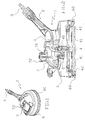
- the aforesaid figures show a tool 1 for a hydro cleaner machine, which is used for washing surfaces.
- Said tool 1 comprises a high pressure conduit 2, having a first end associated with a sleeve 3 for connection to a common lance for hydro cleaner machines, and a second end associated with a rotating device 4 adapted to generate high speed water jets (see fig. 2); said high pressure conduit 2, sleeve 3, and rotating device 4 being adapted to define, within their interior, a conveyor conduit 5 for pressurised water produced by the pump of the hydro cleaner machine.
- the rotating device 4 is supported and protected by an external convex shell 6, wherein the concave side is facing in a downward direction and is open at the bottom, and whose bottom edge is associated with a brush rim 60 adapted to make contact with the surfaces to be washed.
- Said rotating device 4 is composed of a rigid distributor element 40, fixed to the external shell 6 and fed from the high pressure conduit 2, that directs the pressurised water inside two hollow arms 41, integral to each other and mounted to rotate at one end of the distributor element 40 itself (see figures 2, 3, 4); said arms 41 are equipped with nozzles 42 adapted to generate high speed water jets, which, being directed in a manner that coincides with the sloping direction in relation to the surface to be cleaned, rotatably engage the arms 41 themselves (see fig.2).
- a container tank 7 for liquid detergent having a filler mouth 70, and a discharge mouth 71, positioned respectively at the top and at the bottom of the tank 7 itself.
- the tool 1 Associated with the discharge mouth 71 and positioned under the container tank 7, the tool 1 comprises a distributor device 8 for the liquid detergent, which in turn comprises a downflow conduit 80 adapted to connect tank 7 with the exterior, and a closure system for said downflow conduit 80 (see fig. 2); the closure system being adapted to being activated in order to open or close the conduit 80, to permit or prevent the exit of the detergent.
- a distributor device 8 for the liquid detergent which in turn comprises a downflow conduit 80 adapted to connect tank 7 with the exterior, and a closure system for said downflow conduit 80 (see fig. 2); the closure system being adapted to being activated in order to open or close the conduit 80, to permit or prevent the exit of the detergent.
- the downflow conduit 80 is defined by an external cup-shaped envelope 82 equipped at its side surface with two openings, an inlet 83, and an outlet opening 84 respectively, wherein the first opening 83 protrudes and is inserted for a determined distance inside the discharge mouth 71 of the container tank 7, while the second opening 84 is open to the exterior.
- the closure system comprises (see figures 3 and 4): a valve 85 which slides axially, equipped with an obturator 85a, and a rod 85b; a spring 86 adapted to counter the axial motion of the valve 85; and a valve body 87 which, together with the interposition of a sealing means, is partially inserted inside the external envelope 82 in order to present a first portion 87a that intercepts the downflow conduit 80, and a second protruding portion 87b, that associates with the distributor element 40 of the rotating device 4.
- said association between the second portion 87b and the distributor element 40 is obtained by connecting means that comprises: an attachment seat 43, obtained in the distributor element 40, adapted to connect the conveyor conduit 5 with the exterior, and a corresponding insertion section 87c of the valve body 87 adapted to couple with said seat 43 (see figures 3 and 4).
- valve body 87 Inside the valve body 87, at the first portion 87a, are two tubes 89 and 90 connected to each other through a port 91, adapted to define a passage for the detergent from the entry opening 83 towards the exit opening 84; while at the second portion 87b is a casing 92 that presents an end in communication with the conveyor conduit 5, and which is connected to conduit 90 through a guide seat 88 inside which slides the rod 85b of valve 85, together with a seal.
- valve 85 results as being arranged inside the valve body 87 so that the obturator 85a is positioned in the downflow conduit 80 and acts on the port 91, and the rod 86b presents a section of end 86c that extends inside the conveyor conduit 5, contained inside the casing 92.
- valve body 87 shown in the figures, is a body separated from the external envelope 82 of the distributor device 8, it could be possible to foresee its construction in a single body with said external envelope 82, without departing from the context of the described solution.
- the spring 86 acting directly on the obturator 85a, presses it onto the edge of the port 91, thus closing the passage and preventing the exit of any detergent towards the exterior.
- the conveyor conduit 5 is crossed with high-pressure water, which penetrates the casing 92 of the valve body 87, and surrounds the end section 85c of the valve 85 contained inside it.
- the water pressure generates on said end section 85c a force that provokes the axial movement of the valve 85, and therefore of obturator 85a, in contrast with the action of the spring 86; said movement provoking the opening of the port 91, thus permitting the exit of the detergent contained in the downflow conduit 80, through the outlet opening 84.
- tool 1 permits to regulate the amount of detergent that exits when the hydro cleaner machine is in operation.
- the filler mouth 70 of the container tank 7 is vertically aligned with the discharge mouth 71, and is threaded externally to permit the screwing/unscrewing of a closure cap 72, also threaded; said closure cap 72 is associated with a first end of a vertical rod 73, whose second end is equipped with a penetrating body 74 adapted to axially insert inside said discharge mouth 71, and in the particular case shown in the figures, inside the inlet opening 83 of the distributor device 8.
- the size of the passage section of the opening varies, and therefore the amount of detergent that can cross through to reach the down flow conduit 80, will also vary.
- the penetrating body 74 is adapted to be moved axially in order to move progressively from a position that closes the opening 83 completely (see figures 3 and 4), to a position that leaves it completely open, and is moved by activating means.
- said activation means are composed of the closure cap 72 itself, which is integrally associated to the rod 73.
- said regulating means comprise a threaded section 73a on the rod 73, adapted to engage into a corresponding threaded hole 72a realised in cap 72, and a knob 75 associated with the section 73a itself and arranged externally on the container tank 7.
- the knob 75 is manually turned to screw or unscrew the threaded section 73a in the threaded hole 72a: when completely screwed the penetrating body 74 closes the opening 83, then by unscrewing it progressively, the rod 73 and the penetrating body 74 are moved axially in an upward direction thus opening the passage.
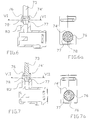
- FIG. 5 a third embodiment of the finding shown in figures 5, 6, and 7 foresees the closure cap 72 associated with the filler mouth 70 by means of a bayonet connection, and the vertical rod 73, having a first end associated rigidly with said closure cap 72, is mounted with an obturator body 74' in a frusto-conical shape on the other end, inside which is a casing 76.
- said obturator body 74' When the closure cap 72 is united with the filler mouth 70, said obturator body 74' is engaged inside a connected seat 77, associated with the discharge mouth 71 and equipped with a recess 78.
- said connected seat 77 is obtained in the end section of the inlet opening 83 of the distributor device 8; said end section extending inside the container tank 7 and presenting the aforesaid recess 78.
- the amount of detergent is regulated by rotating said closure cap 72 in a manner so that in a corresponding manner, the obturator body rotates in a relative manner in the connected seat 77 from a position where the casing 76 faces the recess 78 completely, to a position wherein no passage is defined, or vice versa.
Landscapes
- Cleaning By Liquid Or Steam (AREA)
- Cleaning In General (AREA)
Applications Claiming Priority (1)
| Application Number | Priority Date | Filing Date | Title |
|---|---|---|---|
| ITRE20040104 ITRE20040104A1 (it) | 2004-09-03 | 2004-09-03 | Utensile per macchina idropulitrice adatto al lavaggio di superfici |
Publications (1)
| Publication Number | Publication Date |
|---|---|
| EP1632294A1 true EP1632294A1 (de) | 2006-03-08 |
Family
ID=35365733
Family Applications (1)
| Application Number | Title | Priority Date | Filing Date |
|---|---|---|---|
| EP20050076572 Withdrawn EP1632294A1 (de) | 2004-09-03 | 2005-07-11 | Werkzeug für eine hydrodynamische Reinigungsmaschine geeignet zur Reinigung von Oberflächen |
Country Status (3)
| Country | Link |
|---|---|
| US (1) | US20060049217A1 (de) |
| EP (1) | EP1632294A1 (de) |
| IT (1) | ITRE20040104A1 (de) |
Cited By (1)
| Publication number | Priority date | Publication date | Assignee | Title |
|---|---|---|---|---|
| WO2022095641A1 (zh) * | 2020-11-05 | 2022-05-12 | 杭州脉冲波科技有限公司 | 一种具有高置漏斗及其保护装置的容器盖和容器 |
Citations (4)
| Publication number | Priority date | Publication date | Assignee | Title |
|---|---|---|---|---|
| DE2906612A1 (de) * | 1979-02-21 | 1980-08-28 | Kaercher Gmbh & Co Alfred | Hochdruckreinigungsgeraet |
| DE29721921U1 (de) * | 1997-12-11 | 1998-02-26 | Chih, I-Shun, Lu Kang Chen, Chang Hua | Sprühpistolenanordnung |
| DE19739935A1 (de) * | 1997-09-11 | 1999-03-25 | Wap Reinigungssysteme | Hochdruck-Reinigungsgerät mit Zusatzmittel-Dosiervorrichtung |
| DE20313676U1 (de) * | 2003-09-01 | 2003-11-13 | WSI Wolfgang Suttner-Innovation GmbH & Co. KG, 33689 Bielefeld | Bodenreiniger zum Anschluß an ein Hochdruckaggregat |
Family Cites Families (17)
| Publication number | Priority date | Publication date | Assignee | Title |
|---|---|---|---|---|
| US2584630A (en) * | 1946-11-12 | 1952-02-05 | Soss Mark | Window washing fountain brush |
| US2578994A (en) * | 1948-11-19 | 1951-12-18 | Thomas J Dunaway | Metering device |
| US2795460A (en) * | 1953-03-09 | 1957-06-11 | Ralph E Bletcher | Detergent dispersing device |
| US3355762A (en) * | 1965-10-14 | 1967-12-05 | Matthew S Cavell | Wet scrubbing and vacuum cleaning apparatus |
| SE336307B (de) * | 1970-02-16 | 1971-06-28 | Dopslaff Kg J | |
| US3748050A (en) * | 1971-11-12 | 1973-07-24 | Chaska Chem Co Inc | Cleaner assembly |
| US4191589A (en) * | 1977-04-25 | 1980-03-04 | The John J. Sundheim Family Estate | Method and apparatus for cleaning carpets and surfaces using cleaning fluid |
| US4191590A (en) * | 1977-04-25 | 1980-03-04 | The John J. Sundheim Family Estate | Method and apparatus for cleaning carpets and surfaces using cleaning fluid |
| US4171169A (en) * | 1978-01-03 | 1979-10-16 | Williams Stanley B | Hand held washer |
| US4377018A (en) * | 1981-06-24 | 1983-03-22 | Roto Cleaner, Inc. | Cleaning device for surfaces |
| US4629347A (en) * | 1983-08-11 | 1986-12-16 | Poppitz Harold A | Fluid and brush cleaning apparatus |
| US4792250A (en) * | 1984-10-12 | 1988-12-20 | Bobbie's Automatic Hair Shampooer, Inc. | Shampooing apparatus |
| US5456412A (en) * | 1992-03-16 | 1995-10-10 | Agee; J. Christopher | High pressure surface washing device |
| JP3105778B2 (ja) * | 1995-10-23 | 2000-11-06 | 大淀小松株式会社 | カーペットクリーナー及びカーペットの清浄化方法 |
| US6129094A (en) * | 1997-07-11 | 2000-10-10 | Valley Systems, Inc. | Method of high pressure cleaning |
| US6662600B1 (en) * | 2002-08-07 | 2003-12-16 | Tennant Company | Foamed cleaning liquid dispensing system |
| US7310852B2 (en) * | 2004-01-14 | 2007-12-25 | Gt Investments (Bvi) Limited | Valve assembly |
-
2004
- 2004-09-03 IT ITRE20040104 patent/ITRE20040104A1/it unknown
-
2005
- 2005-07-11 EP EP20050076572 patent/EP1632294A1/de not_active Withdrawn
- 2005-07-12 US US11/178,507 patent/US20060049217A1/en not_active Abandoned
Patent Citations (4)
| Publication number | Priority date | Publication date | Assignee | Title |
|---|---|---|---|---|
| DE2906612A1 (de) * | 1979-02-21 | 1980-08-28 | Kaercher Gmbh & Co Alfred | Hochdruckreinigungsgeraet |
| DE19739935A1 (de) * | 1997-09-11 | 1999-03-25 | Wap Reinigungssysteme | Hochdruck-Reinigungsgerät mit Zusatzmittel-Dosiervorrichtung |
| DE29721921U1 (de) * | 1997-12-11 | 1998-02-26 | Chih, I-Shun, Lu Kang Chen, Chang Hua | Sprühpistolenanordnung |
| DE20313676U1 (de) * | 2003-09-01 | 2003-11-13 | WSI Wolfgang Suttner-Innovation GmbH & Co. KG, 33689 Bielefeld | Bodenreiniger zum Anschluß an ein Hochdruckaggregat |
Cited By (1)
| Publication number | Priority date | Publication date | Assignee | Title |
|---|---|---|---|---|
| WO2022095641A1 (zh) * | 2020-11-05 | 2022-05-12 | 杭州脉冲波科技有限公司 | 一种具有高置漏斗及其保护装置的容器盖和容器 |
Also Published As
| Publication number | Publication date |
|---|---|
| US20060049217A1 (en) | 2006-03-09 |
| ITRE20040104A1 (it) | 2004-12-03 |
Similar Documents
| Publication | Publication Date | Title |
|---|---|---|
| US5827486A (en) | Dispenser | |
| CA2680112C (en) | Cleaning device for cleaning spray guns | |
| JP3179669U (ja) | 一体化浸漬チューブを備えたボトル | |
| US6000632A (en) | Pop-up sprinkler head with maintenance features | |
| CN107260079B (zh) | 用于抽吸清洁机的供料罐 | |
| JPH0477622B2 (de) | ||
| JP2002066198A (ja) | 衣料リフレッシュ用機器のための流体供給源及びリザーバ | |
| US11976448B2 (en) | Filter water spout attached to basin faucet | |
| EP2508268A1 (de) | Wiederbefüllbares Behältersystem für Drucksprüher | |
| US5601210A (en) | Tap for dispensing a drink made from a concentrate, and drinks dispenser apparatus equipped with such a tap | |
| NO145610B (no) | Skumdispenseringsanordning. | |
| US7269879B2 (en) | Solution distribution arrangement for a cleaning machine | |
| US5988911A (en) | Soap and water dispensing system | |
| DK176343B1 (da) | Fremgangsmåde samt anlæg til rensning af et trykværks farvekammer samt rensedyse til brug i sådant anlæg | |
| EP1632294A1 (de) | Werkzeug für eine hydrodynamische Reinigungsmaschine geeignet zur Reinigung von Oberflächen | |
| WO1995002346A1 (en) | Liquid reservoir brush | |
| JPH07171447A (ja) | 添加液混入器と散水ノズル | |
| CN210634782U (zh) | 一种可自清洁的灌装机的灌装机构 | |
| US1637951A (en) | Dispensing device | |
| KR101945403B1 (ko) | 세제공급이 용이한 싱크대용 수전장치 | |
| CN114504259B (zh) | 防回流泡沫吐出容器 | |
| JP2985115B2 (ja) | 槽内洗浄装置 | |
| KR100517756B1 (ko) | 냉온수기용 급수 안내구조 | |
| GB2478141A (en) | A dispenser comprising a spray head and a pouring outlet | |
| CN210058666U (zh) | 一种便于清洗的喷绘用喷枪 |
Legal Events
| Date | Code | Title | Description |
|---|---|---|---|
| PUAI | Public reference made under article 153(3) epc to a published international application that has entered the european phase |
Free format text: ORIGINAL CODE: 0009012 |
|
| AK | Designated contracting states |
Kind code of ref document: A1 Designated state(s): AT BE BG CH CY CZ DE DK EE ES FI FR GB GR HU IE IS IT LI LT LU LV MC NL PL PT RO SE SI SK TR |
|
| AX | Request for extension of the european patent |
Extension state: AL BA HR MK YU |
|
| 17P | Request for examination filed |
Effective date: 20060427 |
|
| 17Q | First examination report despatched |
Effective date: 20060628 |
|
| AKX | Designation fees paid |
Designated state(s): AT BE BG CH CY CZ DE DK EE ES FI FR GB GR HU IE IS IT LI LT LU LV MC NL PL PT RO SE SI SK TR |
|
| STAA | Information on the status of an ep patent application or granted ep patent |
Free format text: STATUS: THE APPLICATION IS DEEMED TO BE WITHDRAWN |
|
| 18D | Application deemed to be withdrawn |
Effective date: 20120201 |