EP1632677A2 - Ensemble roulement pour éolienne - Google Patents
Ensemble roulement pour éolienne Download PDFInfo
- Publication number
- EP1632677A2 EP1632677A2 EP05018549A EP05018549A EP1632677A2 EP 1632677 A2 EP1632677 A2 EP 1632677A2 EP 05018549 A EP05018549 A EP 05018549A EP 05018549 A EP05018549 A EP 05018549A EP 1632677 A2 EP1632677 A2 EP 1632677A2
- Authority
- EP
- European Patent Office
- Prior art keywords
- bearing
- arrangement according
- rolling bearing
- axis
- pin
- Prior art date
- Legal status (The legal status is an assumption and is not a legal conclusion. Google has not performed a legal analysis and makes no representation as to the accuracy of the status listed.)
- Withdrawn
Links
Images
Classifications
-
- F—MECHANICAL ENGINEERING; LIGHTING; HEATING; WEAPONS; BLASTING
- F16—ENGINEERING ELEMENTS AND UNITS; GENERAL MEASURES FOR PRODUCING AND MAINTAINING EFFECTIVE FUNCTIONING OF MACHINES OR INSTALLATIONS; THERMAL INSULATION IN GENERAL
- F16C—SHAFTS; FLEXIBLE SHAFTS; ELEMENTS OR CRANKSHAFT MECHANISMS; ROTARY BODIES OTHER THAN GEARING ELEMENTS; BEARINGS
- F16C27/00—Elastic or yielding bearings or bearing supports, for exclusively rotary movement
- F16C27/04—Ball or roller bearings, e.g. with resilient rolling bodies
-
- F—MECHANICAL ENGINEERING; LIGHTING; HEATING; WEAPONS; BLASTING
- F03—MACHINES OR ENGINES FOR LIQUIDS; WIND, SPRING, OR WEIGHT MOTORS; PRODUCING MECHANICAL POWER OR A REACTIVE PROPULSIVE THRUST, NOT OTHERWISE PROVIDED FOR
- F03D—WIND MOTORS
- F03D80/00—Details, components or accessories not provided for in groups F03D1/00 - F03D17/00
- F03D80/70—Bearing or lubricating arrangements
-
- F—MECHANICAL ENGINEERING; LIGHTING; HEATING; WEAPONS; BLASTING
- F05—INDEXING SCHEMES RELATING TO ENGINES OR PUMPS IN VARIOUS SUBCLASSES OF CLASSES F01-F04
- F05B—INDEXING SCHEME RELATING TO WIND, SPRING, WEIGHT, INERTIA OR LIKE MOTORS, TO MACHINES OR ENGINES FOR LIQUIDS COVERED BY SUBCLASSES F03B, F03D AND F03G
- F05B2250/00—Geometry
- F05B2250/40—Movement of component
- F05B2250/41—Movement of component with one degree of freedom
-
- F—MECHANICAL ENGINEERING; LIGHTING; HEATING; WEAPONS; BLASTING
- F05—INDEXING SCHEMES RELATING TO ENGINES OR PUMPS IN VARIOUS SUBCLASSES OF CLASSES F01-F04
- F05B—INDEXING SCHEME RELATING TO WIND, SPRING, WEIGHT, INERTIA OR LIKE MOTORS, TO MACHINES OR ENGINES FOR LIQUIDS COVERED BY SUBCLASSES F03B, F03D AND F03G
- F05B2250/00—Geometry
- F05B2250/40—Movement of component
- F05B2250/41—Movement of component with one degree of freedom
- F05B2250/411—Movement of component with one degree of freedom in rotation
-
- F—MECHANICAL ENGINEERING; LIGHTING; HEATING; WEAPONS; BLASTING
- F05—INDEXING SCHEMES RELATING TO ENGINES OR PUMPS IN VARIOUS SUBCLASSES OF CLASSES F01-F04
- F05B—INDEXING SCHEME RELATING TO WIND, SPRING, WEIGHT, INERTIA OR LIKE MOTORS, TO MACHINES OR ENGINES FOR LIQUIDS COVERED BY SUBCLASSES F03B, F03D AND F03G
- F05B2250/00—Geometry
- F05B2250/40—Movement of component
- F05B2250/42—Movement of component with two degrees of freedom
-
- F—MECHANICAL ENGINEERING; LIGHTING; HEATING; WEAPONS; BLASTING
- F16—ENGINEERING ELEMENTS AND UNITS; GENERAL MEASURES FOR PRODUCING AND MAINTAINING EFFECTIVE FUNCTIONING OF MACHINES OR INSTALLATIONS; THERMAL INSULATION IN GENERAL
- F16C—SHAFTS; FLEXIBLE SHAFTS; ELEMENTS OR CRANKSHAFT MECHANISMS; ROTARY BODIES OTHER THAN GEARING ELEMENTS; BEARINGS
- F16C2300/00—Application independent of particular apparatuses
- F16C2300/10—Application independent of particular apparatuses related to size
- F16C2300/14—Large applications, e.g. bearings having an inner diameter exceeding 500 mm
-
- F—MECHANICAL ENGINEERING; LIGHTING; HEATING; WEAPONS; BLASTING
- F16—ENGINEERING ELEMENTS AND UNITS; GENERAL MEASURES FOR PRODUCING AND MAINTAINING EFFECTIVE FUNCTIONING OF MACHINES OR INSTALLATIONS; THERMAL INSULATION IN GENERAL
- F16C—SHAFTS; FLEXIBLE SHAFTS; ELEMENTS OR CRANKSHAFT MECHANISMS; ROTARY BODIES OTHER THAN GEARING ELEMENTS; BEARINGS
- F16C2360/00—Engines or pumps
- F16C2360/31—Wind motors
-
- Y—GENERAL TAGGING OF NEW TECHNOLOGICAL DEVELOPMENTS; GENERAL TAGGING OF CROSS-SECTIONAL TECHNOLOGIES SPANNING OVER SEVERAL SECTIONS OF THE IPC; TECHNICAL SUBJECTS COVERED BY FORMER USPC CROSS-REFERENCE ART COLLECTIONS [XRACs] AND DIGESTS
- Y02—TECHNOLOGIES OR APPLICATIONS FOR MITIGATION OR ADAPTATION AGAINST CLIMATE CHANGE
- Y02E—REDUCTION OF GREENHOUSE GAS [GHG] EMISSIONS, RELATED TO ENERGY GENERATION, TRANSMISSION OR DISTRIBUTION
- Y02E10/00—Energy generation through renewable energy sources
- Y02E10/70—Wind energy
- Y02E10/72—Wind turbines with rotation axis in wind direction
Definitions
- the invention relates to a bearing arrangement of a wind turbine for supporting a shaft of the wind turbine.
- a wind turbine in which a rotor of the wind turbine is mounted by means of a double row tapered roller bearing in O arrangement.
- DE 101 02 255 A1 discloses a wind energy plant with a machine carrier attached to a tip of a tower, which on the one hand holds a static generator part and on the other hand supports a rotating generator part and a rotor blade-carrying rotor hub.
- the rotor hub and the rotating generator part are fastened to a common hollow shaft which sits on a single axle sleeve, which is mounted on the machine carrier, via a single, even torque-receiving rolling bearing.
- the rolling bearing is preferably a double-row tapered roller bearing in an X arrangement and has pressure angles of about 45 °.
- An object of the invention is to provide a bearing assembly of a wind turbine, with a long service life of storage can be achieved.
- the invention is based on the following finding: Wind turbines are naturally subject to strongly changing loads due to the generally uneven and sometimes gusty wind blowing, the loads are often amplified by the fact that this natural vibrations of the wind turbine are also stimulated. In this case, a rotor bearing of the main bearing of the wind turbine is subjected within comparatively short time intervals with comparatively large load changes in various directions.
- the aforementioned balancing is achieved in a simple and effective manner.
- acting on the bearing alignment errors and deformations of the rotor shaft without play that is In particular, free of a linear movement possibility of individual components against each other in conjunction with the possibility of abrupt braking of the linear motion, thereby compensating that individual components are free of play and insensitive to jamming against each other and / or at least individual components are intended elastically deformable.
- a long service life of the bearing assembly can be achieved.
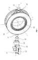
- Figure 1 shows as an embodiment of the invention, a perspective view of a main bearing for a rotor shaft of a wind turbine with a rolling bearing 12 and means for supporting the roller bearing 12.
- the rolling bearing 12 is designed as a backlash adjusted double row tapered roller bearing, in which between an inner ring and an outer ring of the rolling bearing 12, the tapered rollers are arranged.
- the inner ring takes on the rotor shaft, not shown for reasons of clarity, which extends axially along an axis Z.
- two pins 21 and 22 with the housing 14 extending axially in the direction of the axis X are fixed to the outside of a housing 14 substantially enclosing the rolling bearing 12 connected.
- the pins 21 and 22 are in the direction of an axis Y, which is also substantially through a diameter of the rolling bearing 12 and is substantially perpendicular to the axes X and Z, with respect to a bending with a higher rigidity connected to the housing 14 as in Direction of the axis Z.
- For the pin 21 and the web 25 applies accordingly.
- a sleeve 30 formed as a sliding bearing.
- the socket 30 on an insert 32 made of a fiber composite material.
- the socket 30 further has on its outer end face on a back portion 34, with which the socket 30 can be fastened to a fittingly designed mounting block 40 of the rest of the wind turbine, for example by screwing.
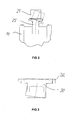
- the back portion 34 is connected to both sides of a plane spanned by the axes X and Y plane with the rest of the wind turbine, so that in particular a deformation of the sleeve 30 along the axis X due to elastic deformations is possible, which is even closer with reference to Figures 2 and 3 is explained.
- the fastening block 40 has a corresponding recess 42 in the region around said plane.
- Figure 3 shows a plan view of the socket 30 and Figure 2 is a plan view of the housing 14 attached Pins 21, wherein in the figures 2 and 3 each an undeformed state with solid lines and dashed lines a deformed state are shown.
- a substantial relief of the rolling bearing 12 can be achieved by loads which act in particular jerkily, starting from the rotor shaft, in the direction of the axis Z and / or in a torque-like manner about the axis Y on the roller bearing 12; but at least an additional load caused thereby of the rolling bearing 12 is reduced to acceptable levels.
- the fiber composite material of the insert 32 of the bushing 30 is selected such that it is capable of elastically compensating any remaining alignment errors of the rotor shaft and of damping vibrations.
- the material itself is non-metallic, so that there is also an insulation of the complete storage, in order to protect against current passage.
- buffer means may be arranged.
- the buffer means may consist of alternating layers of a hard and a rubber-like material, in which case the rubber-like material may be vulcanized on the hard.
- pins 14 are fastened to the housing 14, which pins are thickened in relation to the pins 21 and 22 of FIGS. 1 to 3 at their axial ends facing away from the rolling bearing 12.
- a cup-like element with an inner diameter corresponding to the thickening and an axial extension similar to the pin is pushed over the pin on such a pin, in which case the cup-like element, for example, stored in the socket 30 accordingly.
- the flex-pin principle for the pin together with cup-like element instead of the simply bent bending line of Figures 2 and 3, a double-curved S-like bending line.
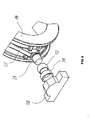
- FIG. 4 shows, as a further exemplary embodiment of the invention, a fragmentary and exploded view in a perspective view of a main bearing of a rotor shaft of a wind energy plant with spherical bearings.
- the description corresponding to FIG. 1 applies correspondingly, so that the same reference numerals as in FIG. 1 are used for the aforementioned elements in FIG.
- the pin 21 is connected in the figure 4 via a designed as a plain bearing spherical plain bearings with the rest of the wind turbine.
- the spherical bearing comprises two mutually movable, mutually compatible bearing parts 52 and 54 facing each other ball-shell-like Surface areas.
- one of the bearing parts 52 or 54 with the pin 21 and the other via a correspondingly formed bearing block 58 is connected to the rest of the wind turbine.
- the arrangement according to FIG. 4 is capable of compensating for any deformation resulting from the rest of the wind power plant, it is designed to a lesser extent than the arrangement according to FIGS. 1 to 3 in the direction of the axis Z and / or outgoing from the rotor shaft.
Landscapes
- Engineering & Computer Science (AREA)
- General Engineering & Computer Science (AREA)
- Mechanical Engineering (AREA)
- Life Sciences & Earth Sciences (AREA)
- Sustainable Development (AREA)
- Sustainable Energy (AREA)
- Chemical & Material Sciences (AREA)
- Combustion & Propulsion (AREA)
- Wind Motors (AREA)
- Support Of The Bearing (AREA)
Applications Claiming Priority (1)
| Application Number | Priority Date | Filing Date | Title |
|---|---|---|---|
| DE102004042235A DE102004042235B4 (de) | 2004-09-01 | 2004-09-01 | Lageranordnung einer Windenergieanlage |
Publications (2)
| Publication Number | Publication Date |
|---|---|
| EP1632677A2 true EP1632677A2 (fr) | 2006-03-08 |
| EP1632677A3 EP1632677A3 (fr) | 2008-07-02 |
Family
ID=35432705
Family Applications (1)
| Application Number | Title | Priority Date | Filing Date |
|---|---|---|---|
| EP05018549A Withdrawn EP1632677A3 (fr) | 2004-09-01 | 2005-08-26 | Ensemble roulement pour éolienne |
Country Status (2)
| Country | Link |
|---|---|
| EP (1) | EP1632677A3 (fr) |
| DE (1) | DE102004042235B4 (fr) |
Cited By (3)
| Publication number | Priority date | Publication date | Assignee | Title |
|---|---|---|---|---|
| WO2013110350A1 (fr) * | 2012-01-27 | 2013-08-01 | Siemens Aktiengesellschaft | Agencement de palier pour éolienne |
| CN106956548A (zh) * | 2017-05-17 | 2017-07-18 | 中冶赛迪工程技术股份有限公司 | 一种微调心滚轮 |
| WO2019008350A1 (fr) * | 2017-07-04 | 2019-01-10 | InSight Analytics Solutions Limited | Agencement de palier d'arbre principal |
Families Citing this family (2)
| Publication number | Priority date | Publication date | Assignee | Title |
|---|---|---|---|---|
| DE102007054379A1 (de) * | 2007-11-14 | 2009-05-20 | Schaeffler Kg | Lageranordnung einer Rotorwelle einer Windenergieanlage |
| DE102007058165B4 (de) | 2007-11-30 | 2013-06-13 | Ab Skf | Wälzlagerung |
Citations (2)
| Publication number | Priority date | Publication date | Assignee | Title |
|---|---|---|---|---|
| GB2267130A (en) * | 1992-05-18 | 1993-11-24 | Renk Ag | Sliding bearings. |
| EP1197677A2 (fr) * | 2000-10-14 | 2002-04-17 | Franz Mitsch | Support de transmission pour éoliennes |
Family Cites Families (9)
| Publication number | Priority date | Publication date | Assignee | Title |
|---|---|---|---|---|
| DE196034C (fr) * | ||||
| US2687925A (en) * | 1951-06-02 | 1954-08-31 | Thompson Prod Inc | Shaft bearing hanger |
| US2687926A (en) * | 1951-06-19 | 1954-08-31 | Thompson Prod Inc | Bearing support |
| US4256353A (en) * | 1979-05-18 | 1981-03-17 | General Electric Company | Self-aligning bearing |
| DE19930751A1 (de) * | 1999-07-02 | 2001-01-04 | Franz Mitsch | Verfahren zur Reduzierung von Schwingungen in Windkraftanlagen |
| DE10045417B4 (de) * | 2000-09-14 | 2004-02-05 | Trelleborg Automotive Technical Centre Gmbh | Radiallager |
| DE10102255A1 (de) * | 2001-01-19 | 2002-08-01 | Aloys Wobben | Windenergieanlage mit einer Hohlwelle für Rotornabe und Generator |
| JP2002219954A (ja) * | 2001-01-24 | 2002-08-06 | Fuji Heavy Ind Ltd | 車両用プロペラシャフトの支持装置 |
| DE20314660U1 (de) * | 2003-09-23 | 2003-12-04 | Ab Skf | Lagerung für den Rotor einer Windkraftanlage |
-
2004
- 2004-09-01 DE DE102004042235A patent/DE102004042235B4/de not_active Expired - Fee Related
-
2005
- 2005-08-26 EP EP05018549A patent/EP1632677A3/fr not_active Withdrawn
Patent Citations (2)
| Publication number | Priority date | Publication date | Assignee | Title |
|---|---|---|---|---|
| GB2267130A (en) * | 1992-05-18 | 1993-11-24 | Renk Ag | Sliding bearings. |
| EP1197677A2 (fr) * | 2000-10-14 | 2002-04-17 | Franz Mitsch | Support de transmission pour éoliennes |
Cited By (4)
| Publication number | Priority date | Publication date | Assignee | Title |
|---|---|---|---|---|
| WO2013110350A1 (fr) * | 2012-01-27 | 2013-08-01 | Siemens Aktiengesellschaft | Agencement de palier pour éolienne |
| US9670906B2 (en) | 2012-01-27 | 2017-06-06 | Siemens Aktiengesellschaft | Bearing arrangement for a wind turbine |
| CN106956548A (zh) * | 2017-05-17 | 2017-07-18 | 中冶赛迪工程技术股份有限公司 | 一种微调心滚轮 |
| WO2019008350A1 (fr) * | 2017-07-04 | 2019-01-10 | InSight Analytics Solutions Limited | Agencement de palier d'arbre principal |
Also Published As
| Publication number | Publication date |
|---|---|
| DE102004042235A1 (de) | 2006-03-02 |
| DE102004042235B4 (de) | 2013-06-06 |
| EP1632677A3 (fr) | 2008-07-02 |
Similar Documents
| Publication | Publication Date | Title |
|---|---|---|
| DE102017206246A1 (de) | Lageranordnung zur Lagerung eines Rotorblatts einer Windenergieanlage | |
| DE102021210007A1 (de) | Federnd gelagertes Getriebegehäuse | |
| DE102010054318A1 (de) | Rotorlagerung einer Windkraftanlage | |
| WO2007147386A2 (fr) | Palier à roulement à inclinaison réglable | |
| EP4405593B1 (fr) | Unité palier de rotor pour une éolienne et procédé de réglage de la précharge dans une unité palier de rotor | |
| EP0785370A1 (fr) | Assemblage de joint universel pour arbre articulé | |
| EP4242453A1 (fr) | Ensemble train d'entraînement à support de couple, ainsi que transmission industrielle équipée de celui-ci, ainsi que procédé de réglage d'un ensemble train d'entraînement à support de couple et utilisation | |
| EP1197677B1 (fr) | Support de transmission pour éoliennes | |
| DE102010054319A1 (de) | Rotorlagerung einer Windkraftanlage | |
| DE102004042235B4 (de) | Lageranordnung einer Windenergieanlage | |
| EP0362327B1 (fr) | Palier de butee avec compensation d'inclinaison | |
| DE102017205156A1 (de) | Lagereinheit | |
| WO2023062145A1 (fr) | Ensemble palier principal pour éolienne | |
| DE3106069A1 (de) | Zentriervorrichtung | |
| EP4416402A1 (fr) | Ensemble palier principal pour éolienne | |
| DE102011007494B4 (de) | Konzept zum Bereitstellen einer Anlageschulter in einem zylinderförmigen Lagergehäuse | |
| DE102009037392A1 (de) | Wälzlageranordnung zu Axial- und/oder Radiallagerung mit Lagerentlastungsmitteln | |
| DE102009035749A1 (de) | Einlagerkonstruktion sowie Windkraftanlagen mit der Einlagerkonstruktion | |
| DE102007036695A1 (de) | Getriebelageranordnung mit wenigstens einem zweireihigen Schrägkugellager | |
| DE4301178A1 (de) | Kreuzzapfengelenk einer zur Übertragung hoher Drehmomente geeigneten Gelenkwelle | |
| DE102010053473A1 (de) | Zweireihiges Schrägwälzlager | |
| DE102010053671A1 (de) | Mehrreihiges Wälzlager und Rotorlagerung einer Windkraftanlage | |
| EP0976455B1 (fr) | Pignon pour entraînement du type roue dentée/pignon | |
| DE3722572C2 (fr) | ||
| DE29920839U1 (de) | Lagersystem für Zapfen von Zapfenkreuzen und Kreuzgelenkanordnung |
Legal Events
| Date | Code | Title | Description |
|---|---|---|---|
| PUAI | Public reference made under article 153(3) epc to a published international application that has entered the european phase |
Free format text: ORIGINAL CODE: 0009012 |
|
| AK | Designated contracting states |
Kind code of ref document: A2 Designated state(s): AT BE BG CH CY CZ DE DK EE ES FI FR GB GR HU IE IS IT LI LT LU LV MC NL PL PT RO SE SI SK TR |
|
| AX | Request for extension of the european patent |
Extension state: AL BA HR MK YU |
|
| PUAL | Search report despatched |
Free format text: ORIGINAL CODE: 0009013 |
|
| RIC1 | Information provided on ipc code assigned before grant |
Ipc: F16C 35/04 20060101ALI20080520BHEP Ipc: F03D 11/00 20060101AFI20051209BHEP |
|
| AK | Designated contracting states |
Kind code of ref document: A3 Designated state(s): AT BE BG CH CY CZ DE DK EE ES FI FR GB GR HU IE IS IT LI LT LU LV MC NL PL PT RO SE SI SK TR |
|
| AX | Request for extension of the european patent |
Extension state: AL BA HR MK YU |
|
| 17P | Request for examination filed |
Effective date: 20080604 |
|
| 17Q | First examination report despatched |
Effective date: 20081113 |
|
| AKX | Designation fees paid |
Designated state(s): AT BE BG CH CY CZ DE DK EE ES FI FR GB GR HU IE IS IT LI LT LU LV MC NL PL PT RO SE SI SK TR |
|
| GRAP | Despatch of communication of intention to grant a patent |
Free format text: ORIGINAL CODE: EPIDOSNIGR1 |
|
| INTG | Intention to grant announced |
Effective date: 20160114 |
|
| RIC1 | Information provided on ipc code assigned before grant |
Ipc: F03D 80/00 20160101AFI20160113BHEP Ipc: F16C 35/04 20060101ALI20160113BHEP |
|
| STAA | Information on the status of an ep patent application or granted ep patent |
Free format text: STATUS: THE APPLICATION IS DEEMED TO BE WITHDRAWN |
|
| 18D | Application deemed to be withdrawn |
Effective date: 20160525 |