EP1632692A2 - Patin de frein pour l'insertion dans le support de patin de frein d'un érier d'un frein à disque - Google Patents
Patin de frein pour l'insertion dans le support de patin de frein d'un érier d'un frein à disque Download PDFInfo
- Publication number
- EP1632692A2 EP1632692A2 EP05016485A EP05016485A EP1632692A2 EP 1632692 A2 EP1632692 A2 EP 1632692A2 EP 05016485 A EP05016485 A EP 05016485A EP 05016485 A EP05016485 A EP 05016485A EP 1632692 A2 EP1632692 A2 EP 1632692A2
- Authority
- EP
- European Patent Office
- Prior art keywords
- brake
- lining
- disc
- brake pad
- shaft
- Prior art date
- Legal status (The legal status is an assumption and is not a legal conclusion. Google has not performed a legal analysis and makes no representation as to the accuracy of the status listed.)
- Withdrawn
Links
- 238000003780 insertion Methods 0.000 title claims abstract description 9
- 230000037431 insertion Effects 0.000 title claims abstract description 9
- 230000000694 effects Effects 0.000 description 4
- 230000001133 acceleration Effects 0.000 description 2
- 230000002238 attenuated effect Effects 0.000 description 2
- 238000009434 installation Methods 0.000 description 2
- 230000036461 convulsion Effects 0.000 description 1
Images
Classifications
-
- F—MECHANICAL ENGINEERING; LIGHTING; HEATING; WEAPONS; BLASTING
- F16—ENGINEERING ELEMENTS AND UNITS; GENERAL MEASURES FOR PRODUCING AND MAINTAINING EFFECTIVE FUNCTIONING OF MACHINES OR INSTALLATIONS; THERMAL INSULATION IN GENERAL
- F16D—COUPLINGS FOR TRANSMITTING ROTATION; CLUTCHES; BRAKES
- F16D65/00—Parts or details
- F16D65/02—Braking members; Mounting thereof
- F16D65/04—Bands, shoes or pads; Pivots or supporting members therefor
- F16D65/092—Bands, shoes or pads; Pivots or supporting members therefor for axially-engaging brakes, e.g. disc brakes
- F16D65/095—Pivots or supporting members therefor
-
- F—MECHANICAL ENGINEERING; LIGHTING; HEATING; WEAPONS; BLASTING
- F16—ENGINEERING ELEMENTS AND UNITS; GENERAL MEASURES FOR PRODUCING AND MAINTAINING EFFECTIVE FUNCTIONING OF MACHINES OR INSTALLATIONS; THERMAL INSULATION IN GENERAL
- F16D—COUPLINGS FOR TRANSMITTING ROTATION; CLUTCHES; BRAKES
- F16D65/00—Parts or details
- F16D65/02—Braking members; Mounting thereof
- F16D65/04—Bands, shoes or pads; Pivots or supporting members therefor
- F16D65/092—Bands, shoes or pads; Pivots or supporting members therefor for axially-engaging brakes, e.g. disc brakes
-
- F—MECHANICAL ENGINEERING; LIGHTING; HEATING; WEAPONS; BLASTING
- F16—ENGINEERING ELEMENTS AND UNITS; GENERAL MEASURES FOR PRODUCING AND MAINTAINING EFFECTIVE FUNCTIONING OF MACHINES OR INSTALLATIONS; THERMAL INSULATION IN GENERAL
- F16D—COUPLINGS FOR TRANSMITTING ROTATION; CLUTCHES; BRAKES
- F16D55/00—Brakes with substantially-radial braking surfaces pressed together in axial direction, e.g. disc brakes
- F16D2055/0004—Parts or details of disc brakes
- F16D2055/0008—Brake supports
Definitions
- the invention relates to a brake pad for a disc brake.
- a brake pad for a disc brake.
- Such a brake pad consists of a support plate and a friction lining arranged thereon.
- the brake pads are supported in lining shafts and guided for movement perpendicular to the plane of an associated brake disc, wherein a clearance for inserting the brake pads is provided between the brake pads and the walls of the lining shaft.
- a so-called pressure distribution plate is often provided parallel to the brake pad.
- the pressure distribution plate has substantially the same dimensions as the brake pad and is supported and guided in substantially the same way, so that in the context of the invention, the term "brake pad" includes such a pressure distribution plate.
- This leaf spring which is supported in the mounted state of the brake pad against a housing-side, releasable hold-down, has the purpose to keep the brake pad safely even in strong accelerations and / or force effects in the lining shaft.
- forces are mainly compensated perpendicular to the direction of travel / road surface to protect when driving over bumps belonging to the unsprung mass of the motor vehicle brake pads from damage. There are some accelerations of more than 15g.
- the game described between the brake pads and the walls of the lining shaft is made responsible, inter alia, for the partially arising during braking high-frequency squeaking noises. Furthermore, by the said game a short delay of the braking effect, until the brake shoe rests against the brake caliper and this receives the braking force.
- the present invention is therefore based on the object to provide a brake pad, minimized by the squeaking noise and shortens the braking distance become. At the same time, however, the insertion of the brake pads should be as easy as in the prior art.
- the basic idea of the present invention is to design the brake pad and the brake caliper such that the brake pad rests against the inner side of the brake caliper lying in the direction of rotation of the brake discs and is supported there.
- the geometric design of the brake pads should be due to the installation on both sides of the brake disc symmetrical to the center axis, since then identical brake pads can be provided for both mounting sides.
- the invention comprises a brake pad for insertion into a lining shaft of a brake caliper of a disc brake device of a motor vehicle, with a arranged on a support plate friction lining and holding means for, preferably resilient, holder the brake pad in a direction radially to a disc brake of the disc brake device, wherein means for contacting the brake pad are provided in and against the rotational direction of the brake disc in the lining shaft, and the brake pad is formed supporting against the lining shaft.
- holding means known in the art leaf springs in question, which are described for example in DE 103 28 194 and DE 100 26 547.
- the contacting / support of the brake pad for example, between the lying in the direction of rotation of the brake disc bearing surface of the lining shaft and a projection which projects from the underside of the lining shaft upwards, take place. Since the contact surface or the two side surfaces of the lining shaft are arranged parallel to one another, the support between the contact surface and the projection can be effected by chamfering the side surface of the protrusion of the lining shaft pointing in the direction of the contact surface.
- An interchangeability of the two opposing brake pads on a caliper is advantageously ensured by the fact that at least two, preferably symmetrically arranged, recesses are provided in the brake pad, which are substantially congruent with projections of the lining shaft.
- the depressions can either be tapered inwardly or else configured with two parallel side walls. Any other geometrically meaningful shape is also within the scope of the invention.
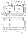
- FIG. 1 shows a brake lining, designated overall by the reference numeral 10, with a support plate 12 and a friction lining 14 arranged thereon.
- the brake pad 10 is shown in its installed state.
- the support plate 12 is formed with two spaced apart projections 16, 18,
- FIG. 1 further shows a leaf spring 20 which is convexly shaped with respect to the outer surface 12a of the support plate 12.
- the leaf spring 20 serves to clamp the brake pad 10 in a brake caliper 50, wherein mainly forces are damped perpendicular to the direction of travel shown.
- the figure also shows in the region of the support plate 12 and - more or less in alignment with it - radially inwardly extending recesses 26, 28, in the region between the projections 16, 18, thus thus below the leaf spring 20 in the assembled state.
- slot-like recesses 26, 28 serve to receive an electrical residual strength indicator for the brake lining 14.
- a holding part of the (not shown) sensor is anchored in the recess 26, a part projects into the recess 28 a piece.
- the brake pad 10 is inserted with a game 11 in the lining shaft 50 of the caliper 55, so that insertion without tools is possible. Shortly before reaching the inserted state of the brake pad 10 shown in Fig. 1, an inner surface 30i of a recess 30 runs on a correspondingly inclined side surface 40s of a projection 40 of the lining shaft 50.
- the recesses 30 are arranged on the lower side of the brake pad 10 and provided both in the support plate 12 and in the friction lining 14.
- Each recess 30 is arranged approximately in the middle of the halves of the brake pad formed by the two Reibbelaghschn 12h1 and 12h2, wherein the recesses 30 are formed on a central axis 10m of the brake pad to each other in mirror image.
- each brake pad 10 can be used on both sides of the caliper 55 in the respective lining shafts 50.
- the friction lining 14 of the opposing brake pads 10 must, of course, each directed inward to contact the intermediate brake disc, not shown, when operating the brake.
- the contacting of the contact surface 50a and the side surface 40s is designed so that a lateral movement of the brake pad 10 in the direction of the brake disc upon actuation of the disc brake device is not hindered. Due to the direct contact of the brake pad 10 on the contact surface 50a, the jerk that normally occurred when the brake lining 10 is being carried along by the brake disc rotating in the direction of travel is greatly attenuated or prevented. Furthermore, a so-called "stop-and-slip" effect is at least greatly attenuated, which would otherwise cause vibrations and associated high-frequency noise emissions (squeaking).
Landscapes
- Engineering & Computer Science (AREA)
- General Engineering & Computer Science (AREA)
- Mechanical Engineering (AREA)
- Braking Arrangements (AREA)
Applications Claiming Priority (1)
| Application Number | Priority Date | Filing Date | Title |
|---|---|---|---|
| DE200410042879 DE102004042879A1 (de) | 2004-09-04 | 2004-09-04 | Bremsbelag zum Einsetzen in einen Belagschacht eines Bremssattels einer Schreibenbremse |
Publications (2)
| Publication Number | Publication Date |
|---|---|
| EP1632692A2 true EP1632692A2 (fr) | 2006-03-08 |
| EP1632692A3 EP1632692A3 (fr) | 2006-03-15 |
Family
ID=35134333
Family Applications (1)
| Application Number | Title | Priority Date | Filing Date |
|---|---|---|---|
| EP05016485A Withdrawn EP1632692A3 (fr) | 2004-09-04 | 2005-07-29 | Patin de frein pour l'insertion dans le support de patin de frein d'un érier d'un frein à disque |
Country Status (2)
| Country | Link |
|---|---|
| EP (1) | EP1632692A3 (fr) |
| DE (1) | DE102004042879A1 (fr) |
Cited By (4)
| Publication number | Priority date | Publication date | Assignee | Title |
|---|---|---|---|---|
| ES2302490A1 (es) * | 2008-03-11 | 2008-07-01 | Eurofren Brakes S.L.U. | Freno de disco con sistema para control de la posicion de montaje de pastillas de freno y pastilla de freno. |
| GB2445835A (en) * | 2007-01-17 | 2008-07-23 | Ford Global Tech Llc | Brake pad having notches therein to reduce braking noise |
| DE102008013514A1 (de) | 2008-03-11 | 2009-09-17 | TRW KFZ-Ausrüstung GmbH | Scheibenbremse mit orientierungsgesichertem Einbau der Bremsbeläge |
| WO2018139549A1 (fr) * | 2017-01-30 | 2018-08-02 | 曙ブレーキ工業株式会社 | Plaquette de frein à disque et dispositif de frein à disque |
Families Citing this family (3)
| Publication number | Priority date | Publication date | Assignee | Title |
|---|---|---|---|---|
| DE102006036277B4 (de) * | 2006-08-03 | 2015-12-31 | Knorr-Bremse Systeme für Nutzfahrzeuge GmbH | Scheibenbremse, insbesondere für ein Nutzfahrzeug |
| DE102013220634A1 (de) | 2013-10-14 | 2015-04-30 | Volkswagen Aktiengesellschaft | Bremsträger |
| DE102019101219A1 (de) * | 2019-01-17 | 2020-07-23 | Wabco Europe Bvba | Bremsenträger und Bremsbelag für Scheibenbremsen von Nutzahrzeugen |
Family Cites Families (12)
| Publication number | Priority date | Publication date | Assignee | Title |
|---|---|---|---|---|
| FR2232701B1 (fr) * | 1973-06-05 | 1977-02-04 | Dba | |
| JPS6030857B2 (ja) * | 1979-06-30 | 1985-07-18 | トヨタ自動車株式会社 | デイスクブレ−キ |
| DE8615015U1 (de) * | 1986-06-04 | 1987-10-01 | Lucas Industries P.L.C., Birmingham, West Midlands | Blattfeder zum Niederhalten der Belag-Tragplatte einer Scheibenbremse |
| JPH059536Y2 (fr) * | 1988-07-18 | 1993-03-09 | ||
| DE4020287A1 (de) * | 1990-06-26 | 1992-01-02 | Knorr Bremse Ag | Belaghalterung in scheibenbremsen fuer strassenfahrzeuge, insbesondere nutzfahrzeuge |
| US6039155A (en) * | 1998-03-27 | 2000-03-21 | Robert Bosch Technology Corporation | Disc brake |
| DE10026547C2 (de) * | 2000-05-27 | 2003-10-02 | Hermann Peters Gmbh & Co | Bremsbelag für eine Scheibenbremse |
| JP2003014010A (ja) * | 2001-06-28 | 2003-01-15 | Tokico Ltd | ディスクブレーキ |
| JP2003014009A (ja) * | 2001-06-29 | 2003-01-15 | Tokico Ltd | ディスクブレーキ |
| US20040154885A1 (en) * | 2002-07-22 | 2004-08-12 | Giovanni Gotti | Pad for caliper of disc brake |
| ATE367539T1 (de) * | 2003-04-28 | 2007-08-15 | Bpw Bergische Achsen Kg | Bremssattel für eine scheibenbremse sowie bremspad für eine scheibenbremse |
| DE10328194B3 (de) * | 2003-06-24 | 2004-12-23 | Hermann Peters Gmbh & Co. | Bremsbelag für eine Scheibenbremse |
-
2004
- 2004-09-04 DE DE200410042879 patent/DE102004042879A1/de not_active Ceased
-
2005
- 2005-07-29 EP EP05016485A patent/EP1632692A3/fr not_active Withdrawn
Cited By (9)
| Publication number | Priority date | Publication date | Assignee | Title |
|---|---|---|---|---|
| GB2445835A (en) * | 2007-01-17 | 2008-07-23 | Ford Global Tech Llc | Brake pad having notches therein to reduce braking noise |
| GB2445835B (en) * | 2007-01-17 | 2011-08-03 | Ford Global Tech Llc | A brake moan and groan splitter |
| ES2302490A1 (es) * | 2008-03-11 | 2008-07-01 | Eurofren Brakes S.L.U. | Freno de disco con sistema para control de la posicion de montaje de pastillas de freno y pastilla de freno. |
| ES2302490B1 (es) * | 2008-03-11 | 2009-04-16 | Eurofren Brakes S.L.U. | Freno de disco con sistema para control de la posicion de montaje de pastillas de freno y pastilla de freno. |
| WO2009112610A1 (fr) | 2008-03-11 | 2009-09-17 | Eurofren Brakes, S.L.U. | Frein à disque à système de commande de la position de montage des plaquettes de frein et plaquette de frein |
| DE102008013514A1 (de) | 2008-03-11 | 2009-09-17 | TRW KFZ-Ausrüstung GmbH | Scheibenbremse mit orientierungsgesichertem Einbau der Bremsbeläge |
| CN102124246A (zh) * | 2008-03-11 | 2011-07-13 | Trw汽车西班牙有限公司 | 带有检查制动器衬块安装位置的系统的盘式制动器和制动器衬块 |
| WO2018139549A1 (fr) * | 2017-01-30 | 2018-08-02 | 曙ブレーキ工業株式会社 | Plaquette de frein à disque et dispositif de frein à disque |
| CN110234900A (zh) * | 2017-01-30 | 2019-09-13 | 曙制动器工业株式会社 | 盘式制动器用衬块以及盘式制动装置 |
Also Published As
| Publication number | Publication date |
|---|---|
| EP1632692A3 (fr) | 2006-03-15 |
| DE102004042879A1 (de) | 2006-03-09 |
Similar Documents
| Publication | Publication Date | Title |
|---|---|---|
| EP3516255B1 (fr) | Frein à disque pour véhicule utilitaire et jeu de garnitures de frein | |
| DE102012102584A1 (de) | Scheibenbremse mit Rückstelleinrichtung und Bremsbelag | |
| DE69515257T2 (de) | Scheibenbremse | |
| DE19956968A1 (de) | Bremsklotzbügel für Scheibenbremsen | |
| DE112007003053T5 (de) | Vertikale Bremssattel-Halteranordnung | |
| EP1532380A1 (fr) | Support de frein a disque a etrier flottant pourvu d'un ressort de guidage de garnitures de frein | |
| DE102006034839A1 (de) | Über coulombsche Reibung gedämpfte Bremssattelhalterung für Scheibenbremsen | |
| DE2812718A1 (de) | Scheibenbremse des schwimmsatteltyps | |
| WO2014079870A1 (fr) | Dispositif de fixation de garniture de frein pour un frein à disque d'un véhicule automobile | |
| WO2019238657A1 (fr) | Frein à disque doté d'un dispositif de rappel et jeu de patins de frein d'un tel frein à disque | |
| DE3744341C2 (fr) | ||
| WO2019115286A1 (fr) | Frein à disque pour véhicule utilitaire et jeu de garnitures de frein | |
| DE3910154A1 (de) | Blattfeder zum niederhalten der bremsbelagtraeger in einer scheibenbremse | |
| DE102010019470B4 (de) | Scheibenbremse für ein Nutzfahrzeug sowie Bremsbelag für eine Scheibenbremse | |
| EP1067304B1 (fr) | Frein à disque et sa garniture de frein | |
| EP1632692A2 (fr) | Patin de frein pour l'insertion dans le support de patin de frein d'un érier d'un frein à disque | |
| WO2006048267A1 (fr) | Plaquette d'un frein a disque | |
| DE2505879B2 (de) | Führung für den Sattel bzw. Rahmen einer Schwimmsattel- bzw. Schwinunrahmen-Teilbelag-Scheibenbremse, insbesondere für Kraftfahrzeuge | |
| DE102016120478B4 (de) | Scheibenbremse für ein Nutzfahrzeug sowie Bremsbelag für eine Scheibenbremse | |
| EP0570442A1 (fr) | Segment de frein. | |
| DE4110869C2 (de) | Festsattel-Teilbelagscheibenbremse | |
| AT519090A4 (de) | Bremsbelag | |
| AT500184B1 (de) | Zentriereinrichtung für bremssättel | |
| EP0826113B1 (fr) | Frein a disque a garniture partielle | |
| DE102008005432A1 (de) | Scheibenbremse für ein Nutzfahrzeug und Bremsbelag für eine Scheibenbremse |
Legal Events
| Date | Code | Title | Description |
|---|---|---|---|
| PUAI | Public reference made under article 153(3) epc to a published international application that has entered the european phase |
Free format text: ORIGINAL CODE: 0009012 |
|
| PUAL | Search report despatched |
Free format text: ORIGINAL CODE: 0009013 |
|
| AK | Designated contracting states |
Kind code of ref document: A2 Designated state(s): AT BE BG CH CY CZ DE DK EE ES FI FR GB GR HU IE IS IT LI LT LU LV MC NL PL PT RO SE SI SK TR |
|
| AX | Request for extension of the european patent |
Extension state: AL BA HR MK YU |
|
| AK | Designated contracting states |
Kind code of ref document: A3 Designated state(s): AT BE BG CH CY CZ DE DK EE ES FI FR GB GR HU IE IS IT LI LT LU LV MC NL PL PT RO SE SI SK TR |
|
| AX | Request for extension of the european patent |
Extension state: AL BA HR MK YU |
|
| AKX | Designation fees paid | ||
| STAA | Information on the status of an ep patent application or granted ep patent |
Free format text: STATUS: THE APPLICATION IS DEEMED TO BE WITHDRAWN |
|
| 18D | Application deemed to be withdrawn |
Effective date: 20060916 |
|
| REG | Reference to a national code |
Ref country code: DE Ref legal event code: 8566 |