EP1632711A2 - Support pour sources de lumière - Google Patents
Support pour sources de lumière Download PDFInfo
- Publication number
- EP1632711A2 EP1632711A2 EP05450145A EP05450145A EP1632711A2 EP 1632711 A2 EP1632711 A2 EP 1632711A2 EP 05450145 A EP05450145 A EP 05450145A EP 05450145 A EP05450145 A EP 05450145A EP 1632711 A2 EP1632711 A2 EP 1632711A2
- Authority
- EP
- European Patent Office
- Prior art keywords
- base
- support body
- unit according
- carrying unit
- light source
- Prior art date
- Legal status (The legal status is an assumption and is not a legal conclusion. Google has not performed a legal analysis and makes no representation as to the accuracy of the status listed.)
- Granted
Links
Images


Classifications
-
- F—MECHANICAL ENGINEERING; LIGHTING; HEATING; WEAPONS; BLASTING
- F21—LIGHTING
- F21V—FUNCTIONAL FEATURES OR DETAILS OF LIGHTING DEVICES OR SYSTEMS THEREOF; STRUCTURAL COMBINATIONS OF LIGHTING DEVICES WITH OTHER ARTICLES, NOT OTHERWISE PROVIDED FOR
- F21V19/00—Fastening of light sources or lamp holders
- F21V19/001—Fastening of light sources or lamp holders the light sources being semiconductors devices, e.g. LEDs
- F21V19/0015—Fastening arrangements intended to retain light sources
-
- B—PERFORMING OPERATIONS; TRANSPORTING
- B60—VEHICLES IN GENERAL
- B60Q—ARRANGEMENT OF SIGNALLING OR LIGHTING DEVICES, THE MOUNTING OR SUPPORTING THEREOF OR CIRCUITS THEREFOR, FOR VEHICLES IN GENERAL
- B60Q1/00—Arrangement of optical signalling or lighting devices, the mounting or supporting thereof or circuits therefor
- B60Q1/26—Arrangement of optical signalling or lighting devices, the mounting or supporting thereof or circuits therefor the devices being primarily intended to indicate the vehicle, or parts thereof, or to give signals, to other traffic
- B60Q1/2696—Mounting of devices using LEDs
-
- F—MECHANICAL ENGINEERING; LIGHTING; HEATING; WEAPONS; BLASTING
- F21—LIGHTING
- F21S—NON-PORTABLE LIGHTING DEVICES; SYSTEMS THEREOF; VEHICLE LIGHTING DEVICES SPECIALLY ADAPTED FOR VEHICLE EXTERIORS
- F21S43/00—Signalling devices specially adapted for vehicle exteriors, e.g. brake lamps, direction indicator lights or reversing lights
- F21S43/10—Signalling devices specially adapted for vehicle exteriors, e.g. brake lamps, direction indicator lights or reversing lights characterised by the light source
- F21S43/13—Signalling devices specially adapted for vehicle exteriors, e.g. brake lamps, direction indicator lights or reversing lights characterised by the light source characterised by the type of light source
- F21S43/14—Light emitting diodes [LED]
-
- H—ELECTRICITY
- H05—ELECTRIC TECHNIQUES NOT OTHERWISE PROVIDED FOR
- H05K—PRINTED CIRCUITS; CASINGS OR CONSTRUCTIONAL DETAILS OF ELECTRIC APPARATUS; MANUFACTURE OF ASSEMBLAGES OF ELECTRICAL COMPONENTS
- H05K1/00—Printed circuits
- H05K1/18—Printed circuits structurally associated with non-printed electric components
- H05K1/189—Printed circuits structurally associated with non-printed electric components characterised by the use of flexible or folded printed circuits
-
- F—MECHANICAL ENGINEERING; LIGHTING; HEATING; WEAPONS; BLASTING
- F21—LIGHTING
- F21Y—INDEXING SCHEME ASSOCIATED WITH SUBCLASSES F21K, F21L, F21S and F21V, RELATING TO THE FORM OR THE KIND OF THE LIGHT SOURCES OR OF THE COLOUR OF THE LIGHT EMITTED
- F21Y2115/00—Light-generating elements of semiconductor light sources
- F21Y2115/10—Light-emitting diodes [LED]
-
- H—ELECTRICITY
- H05—ELECTRIC TECHNIQUES NOT OTHERWISE PROVIDED FOR
- H05K—PRINTED CIRCUITS; CASINGS OR CONSTRUCTIONAL DETAILS OF ELECTRIC APPARATUS; MANUFACTURE OF ASSEMBLAGES OF ELECTRICAL COMPONENTS
- H05K2201/00—Indexing scheme relating to printed circuits covered by H05K1/00
- H05K2201/09—Shape and layout
- H05K2201/09009—Substrate related
- H05K2201/09081—Tongue or tail integrated in planar structure, e.g. obtained by cutting from the planar structure
-
- H—ELECTRICITY
- H05—ELECTRIC TECHNIQUES NOT OTHERWISE PROVIDED FOR
- H05K—PRINTED CIRCUITS; CASINGS OR CONSTRUCTIONAL DETAILS OF ELECTRIC APPARATUS; MANUFACTURE OF ASSEMBLAGES OF ELECTRICAL COMPONENTS
- H05K2201/00—Indexing scheme relating to printed circuits covered by H05K1/00
- H05K2201/09—Shape and layout
- H05K2201/09009—Substrate related
- H05K2201/09118—Moulded substrate
-
- H—ELECTRICITY
- H05—ELECTRIC TECHNIQUES NOT OTHERWISE PROVIDED FOR
- H05K—PRINTED CIRCUITS; CASINGS OR CONSTRUCTIONAL DETAILS OF ELECTRIC APPARATUS; MANUFACTURE OF ASSEMBLAGES OF ELECTRICAL COMPONENTS
- H05K2201/00—Indexing scheme relating to printed circuits covered by H05K1/00
- H05K2201/10—Details of components or other objects attached to or integrated in a printed circuit board
- H05K2201/10007—Types of components
- H05K2201/10106—Light emitting diode [LED]
-
- H—ELECTRICITY
- H05—ELECTRIC TECHNIQUES NOT OTHERWISE PROVIDED FOR
- H05K—PRINTED CIRCUITS; CASINGS OR CONSTRUCTIONAL DETAILS OF ELECTRIC APPARATUS; MANUFACTURE OF ASSEMBLAGES OF ELECTRICAL COMPONENTS
- H05K2201/00—Indexing scheme relating to printed circuits covered by H05K1/00
- H05K2201/10—Details of components or other objects attached to or integrated in a printed circuit board
- H05K2201/10431—Details of mounted components
- H05K2201/10598—Means for fastening a component, a casing or a heat sink whereby a pressure is exerted on the component towards the PCB
Definitions
- the invention relates to a light source support unit having a support body, which has at least one mounting region for mounting at least one light source, preferably an LED, and which defines a reference plane, opposite which the Lichtabstrahlraum the light source in the predetermined operating position is inclined.
- Such carrying units are particularly useful for mounting lights such as taillights, turn signals, etc., in automobiles, the technology being to use light emitting diodes (LEDs) for such automotive lights.
- LEDs light emitting diodes
- 10 or 20 LEDs can be used in the course of the realization of a taillight, a brake light or a flashing light, depending on the strength of the LEDs.
- the support unit with the support body can not be mounted in a precise right-angled or parallel orientation, relative to the direction of travel of the motor vehicle, on a body part of the latter, so that when mounting the light sources, in particular LEDs, on the support body in a robot (robot) a three-dimensional (3D) loading or mounting is required.
- the invention is based on the finding that a 2D-loading, as it is known from the assembly of printed circuit boards ago, is then possible when mounting light sources on support units of the type in question here, if the mounting area of the support unit is not fixed the support unit is provided, but by a relative thereto (or to the reference plane) adjustable part is formed, which is finally made possible by the adjustment in the final operating position desired alignment of the light source.
- the light source support unit according to the invention of the type mentioned above is characterized in that the mounting portion is formed by a base movably connected to the rest of the support body, which is movable relative to the support body from an initial light source mounting position, corresponding to the reference plane, in the operating position.
- the invention is therefore based on the concept of a fixed support body, in which the reference plane - are arranged obliquely to each other - due to the mounting position in the respective device, in particular on a body part of a motor vehicle, and the mounting plane of the light source (or accordingly the Lichtabstrahlraum the light source) , whereby the 3D assembly is necessary, and it provides instead an education, in which a part of the support body, namely the assembly area for the light source forming base is movable relative to the rest of the support body, so that the base (at least) two Positions opposite to the rest of the support body can take: In the one position, the mounting position for the light source, such an orientation of the mounting portion of the base is given that an assembly with the light source in a 2D technique is possible.
- the base is mounted together with the light source mounted in the other position, the operating position, in which the aforementioned Angular position is given relative to the reference plane. Since the required inclination, ie size of the angle, for this angular position is known from the outset, and the operating position of the base relative to the usual support body can be determined by positioning, such as stops, etc., depending on the required angular position.
- the support body can simply be at least substantially plate-shaped, wherein the (upper) plate plane defines the reference plane or parallel to the reference plane.
- the base may further be arranged on the actual support body on an edge, but it is preferably in a window-like opening of the supporting body - protected - arranged, with the fixing of the base in the operating position is then possible with a particularly high stability.
- the base is pivotally connected to the support body.
- the base is displaceable and pivotable relative to the support member.
- the base is integral with the support body and is pivotally connected to it via a film hinge.
- a conductor track pattern is provided for producing the electrical connections on the support body, and in the case of the last-mentioned embodiment of the support unit according to the invention, it is particularly advantageous if flexible conductor tracks for the electrical connection lead on the base and on the support body over the region of the film hinge the light source are arranged.
- Such flexible interconnects are known per se, and they can be provided for example by means of the so-called MID technology (MID - Molded Interconnect Device).
- MID technology MID - Molded Interconnect Device
- prefabricated strip conductors are applied, for example in a hot stamping process on the substrate, in this case the support body or base, with heat and pressure application.
- the interconnect elements may themselves be provided with a thermally activatable or else inorganic adhesive layer, but they may also be pressed in as metallic interconnects into locally softened regions of the substrate (support body, base) directly become. It is advantageous in any case in this technique in the context of the invention that the surface of the base is in this output mounting position in a plane with the surface of the rest of the support body, so that not only the assembly with the light sources in 2D technology, but also the simple application of the flexible conductor tracks is made possible.
- the base is fixable in its operating position on the support body.
- the base and the supporting body have cooperating locking elements in the operating position.
- the base has at least one protruding pin projection, which snaps into a catch on the support body.
- the catch i. the detent recess, is formed according to the shape of the pin projection, and for snapping the pin projection can be provided in a conventional manner inclined surfaces on the catch forming portion of the support body.
- the detent on the support body is formed like a niche in a support member provided on the bearing part, and if the support body further includes a stop for the journal projection is provided on which the latter rests in the operating position.
- two laterally projecting pin projections are provided on both sides of the base;
- the base has a latchable with the support snap hooks.
- the snap hook can simply like a tab from the rest of the base, in particular of its plate-shaped main body, stand out;
- a web is advantageously provided on the support body, with which the snap hook engages behind in the operating position with a hook end.
- the base for example, strip-shaped, has positioning projections for an LED.
- the support body has openings aligned with the latching elements in the mounting position of the base.
- a molded part with corresponding projections which form the openings in the support body and which form the latching elements provided in alignment with the openings are provided, wherein then a demolding by retracting the projections of the molded part through the openings is possible.
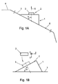
- a support unit 1 is schematically illustrated with a mounted light source 2 in the form of an LED module 3 in a mounted on a body part or other motor vehicle component 4 of an otherwise not shown motor vehicle operating position.
- the thus realized motor vehicle light such as a taillight or a brake light, has a Lichtabstrahlraum, which is illustrated with an arrow 5; this light emission direction 5 closes one of 90 ° deviating angle ⁇ with the surface 6 of the body part 4, wherein by this surface 6 a reference plane 7 is defined. Accordingly, there is an angular position (angle ⁇ ) between the light emission direction 5 and the reference plane 7.
- This reference plane 7 can also be seen in Fig. 1B, in which Fig. 1B, the operation of the loading of the support unit 1 is illustrated with the LED module 3 in a placement machine having a pad for the support units 3 (or support), the also determines the reference plane 7.
- a three-dimensional movement or assembly of the LED module 3 is required, which is also illustrated by the coordinate axes x-y-z in FIG. 1B.
- the angle ⁇ given thereby, different from 90 °, as a consequence of the angular position of the LED module 3 in the mounted position relative to the reference plane 7, is also illustrated in FIG.
- FIGS. 2 and 3 such a support unit 10 according to the invention is illustrated in Figures 2 and 3 in the final operating position (Figure 2) and in the original light source mounting position or home position ( Figure 3).
- the support unit 10 has a - at least substantially - plate-shaped support body 11, the upper or upper plate plane 12 now as a reference plane corresponding to the reference plane 7 in the Fig. 1A and 1B can be considered. below Therefore, this top plate plane should also be referred to as reference plane 12.
- a window-like opening 13 is provided in the actual mounting portion 14, a base 15 is provided, which is movable relative to the support body 11.
- the base 15 is pivotally connected to the support body 11 in an edge region 16 so that it is in an angular position from the starting position shown in FIG. 3, in which its upper plane or mounting surface is in a plane to the reference plane 12 Fig. 2, namely the operating position, cf. Also Fig. 1, can be swung up.
- conductor tracks 18 in a conventional manner on the upper side of the support body 11, the film hinge 17 and the base 15 are mounted to provide electrical connections to the held as a light source 2 between positioning stops 19 LED module 3.
- the LED module 3 may conventionally be a so-called SMD LED (SMD - Surface Mounted Device), and the printed conductors 18 may be present in the so-called MID technology (MID - Molded interconnect device - molded interconnect device); As known per se, such MID conductor tracks are applied to the support body 11 and the base 15 together with the film hinge 17 in a hot embossing process, for example, before the LED 3 is attached.
- the base 15 is provided substantially at the bottom with a total of three locking elements 20 in a kind of three-point storage in the operating position with associated latching and contact elements of the support body 11 cooperate, as will be explained in more detail below with reference to FIGS. 12 to 17.
- the locking elements 20 are provided in the illustrated embodiment such that an injection molding of the entire support unit 10 with a simple injection mold consisting of a top mold and a mold bottom, without lateral (core) slide, is possible. Accordingly, the plate-shaped support body 11 to these locking elements 20 aligned openings, as will be explained in more detail below, and these openings are formed during injection molding by appropriate form projections, which serve to form the respective latching elements 20.
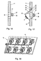
- this snap hook 23 extends at right angles down when the base 15 is in the starting position shown in FIGS. 2 to 9, and it has an angled hook end 25, with which he in the final operating position shown in FIGS. 12 to 18 a provided in the window 13 of the support body 11, transversely extending web 26 engages behind, see. in particular FIG. 17.
- the base 15 has perpendicularly from its plate-shaped main body 24 downwardly projecting legs 27, 28, see. in particular Fig. 5 and 6, each carrying one of the pin projections 21 and 22, and at the front as shown in FIG. 2 front (lower) end by a likewise vertically projecting downward wall 29 to form a stable three-sided frame structure ,
- the detents 35, 36 are in turn from the plate-shaped support body Mounted at right angles downwardly projecting bearing parts or legs 37 and 38, as shown in particular in Figs. 11 and 12 can be seen. Since these legs 37, 38 can not be engaged behind by any other elements, and thus can be formed directly on the underside of the plate-shaped supporting body 11, they are not critical during molding by injection molding, but, as is apparent in particular from FIG. 12, the detents 35, 36 of the pin protrusions 21, 22 in the operating position (see Fig. 12, but also Fig. 17 and 18) engaged behind, so that both their top and its bottom are to be formed below the plate body of the support body 11, thereby the openings 33, 34 arise.
- the detents 35, 36 are in the form of latching niches (see Fig. 17 and 18) formed with corresponding to the pin projections 21, 22 in cross-section adapted, in particular circular arc-shaped detent niches.
- the detents 35, 36 are further provided on their underside with inclined surfaces 39, 40, see, for example, Fig. 12, where the pin projections 21, 22 as shown in Figure 11 can be seen during pivoting of the base 15 in the operating position, in particular with bevelled ends along. while bending the bearing parts or legs 37, 38, until they are present on the detents 35, 36 and snap under elastic pivoting back of the bearing parts or the legs 37, 38 in the notches 35, 36.
- the traces 18 applied, after which the support unit 10 in a heating tunnel (not shown) is heated to heat an applied solder or conductor material, after which the LED 3 is applied between the positioning strips 19 in the 2D-mounter (not shown). After solidification of the solder or conductor material, the LED 3 sits firmly on the base 15th
- the support unit 10 When loading in 2D technology, the support unit 10 may rest for example on an intermittently driven conveyor, which has recesses in the region of the base 15 (with the lower pin projections 21, 22 on the legs 37, 38 and the snap hook 23), so that plate-shaped support body 11, moreover, with its approximately from Fig. 6 apparent underside can rest flat on the conveyor.
- an intermittently driven conveyor which has recesses in the region of the base 15 (with the lower pin projections 21, 22 on the legs 37, 38 and the snap hook 23), so that plate-shaped support body 11, moreover, with its approximately from Fig. 6 apparent underside can rest flat on the conveyor.
- FIG. 2 After loading the base 15 is pivoted into its operating position shown in FIG. 2, wherein from Fig. 10 and 11, an intermediate position in this pivoting is visible.
- FIGS. 11 and 12 show how the pin protrusions 21, 22 are finally fixed in the operating position by latching to the elements 41/35 and 42/36.
- the snap hook 23 is latched with its hook end 25 on the web 26, wherein it rests with its underside on a shoulder 43 (see Fig. 17) of the support body 11.
- the base 15 is securely and stably held in its operating position shown in FIGS. 2 and 12 to 17, in the nature of the mentioned "three-point storage", which is given by the two lateral pin projections 21, 22 and the snap hook 23 ,
- the positions and dimensions of the individual locking elements 20 are of course depending on the angular position of the base 15 relative to the rest of the support body 11 set in the operating position.
- different angular positions ie with different angles ⁇ (see FIGS. 1A and 1B)
- the respective angular position may be determined by the length of the snap hook 23, by the position of the webs 26 and the shoulder 43, by the position of the pin protrusions 21, 22 (ie the length of the legs 27, 28) and the length of the legs 37, 38 and the positions of the detents 35, 36 are determined.
- FIG. 19 schematically shows a support unit 10 with a plurality of sockets 15, with a corresponding conductor pattern 18, in order to illustrate that on a common plate-shaped support body 11 with a plurality of windows 13 and sockets 15 a corresponding plurality of LEDs 3 or generally light sources 2 (see Fig. 1) can be provided, wherein in a corresponding manner as explained above with reference to FIGS. 2 to 18, the inventive technique with regard to the desired 2D assembly can be applied.
- LEDs may be provided, and it is also possible to have more than one LED 3, e.g. two, but also ten or twenty.
- any suitable for the particular application plastic material can be used.
- a thermoplastic is preferred.
Landscapes
- Engineering & Computer Science (AREA)
- General Engineering & Computer Science (AREA)
- Microelectronics & Electronic Packaging (AREA)
- Mechanical Engineering (AREA)
- Physics & Mathematics (AREA)
- Optics & Photonics (AREA)
- Fastening Of Light Sources Or Lamp Holders (AREA)
- Lighting Device Outwards From Vehicle And Optical Signal (AREA)
- Arrangements Of Lighting Devices For Vehicle Interiors, Mounting And Supporting Thereof, Circuits Therefore (AREA)
Applications Claiming Priority (1)
| Application Number | Priority Date | Filing Date | Title |
|---|---|---|---|
| AT0146504A AT500892B1 (de) | 2004-09-01 | 2004-09-01 | Lichtquellen-trageinheit |
Publications (3)
| Publication Number | Publication Date |
|---|---|
| EP1632711A2 true EP1632711A2 (fr) | 2006-03-08 |
| EP1632711A3 EP1632711A3 (fr) | 2008-05-07 |
| EP1632711B1 EP1632711B1 (fr) | 2009-11-18 |
Family
ID=35445714
Family Applications (1)
| Application Number | Title | Priority Date | Filing Date |
|---|---|---|---|
| EP05450145A Expired - Lifetime EP1632711B1 (fr) | 2004-09-01 | 2005-08-31 | Support pour sources de lumière |
Country Status (3)
| Country | Link |
|---|---|
| EP (1) | EP1632711B1 (fr) |
| AT (1) | AT500892B1 (fr) |
| DE (1) | DE502005008519D1 (fr) |
Cited By (7)
| Publication number | Priority date | Publication date | Assignee | Title |
|---|---|---|---|---|
| EP1936259A1 (fr) * | 2006-12-21 | 2008-06-25 | Zizala Lichtsysteme GmbH | Système de montage destiné au montage de diodes luminescentes dans un boîtier d'une unité d'éclairage ou un phare de véhicule |
| WO2009107085A3 (fr) * | 2008-02-26 | 2009-12-10 | Easy International S.R.L. | Lampe à led et son procédé de conception |
| DE102010041469A1 (de) * | 2010-09-27 | 2012-03-29 | Zumtobel Lighting Gmbh | LED-Leuchte mit auswechselbarer Lichtquelle |
| DE102013113009A1 (de) * | 2013-11-25 | 2015-05-28 | Osram Opto Semiconductors Gmbh | Gehäuse für einen Halbleiterchip, Gehäuseverbund, Halbleiterbauelement und Verfahren zur Herstellung eines Halbleiterbauelements |
| US20150369457A1 (en) * | 2014-06-23 | 2015-12-24 | Epistar Corporation | Light-Emitting Device |
| DE102015206801A1 (de) * | 2015-04-15 | 2016-10-20 | Osram Gmbh | Beleuchtungsvorrichtung mit LEDs |
| US10150408B2 (en) * | 2014-07-28 | 2018-12-11 | Yazaki Corporation | Illumination device |
Families Citing this family (3)
| Publication number | Priority date | Publication date | Assignee | Title |
|---|---|---|---|---|
| DE102015106929B3 (de) * | 2015-05-04 | 2016-09-01 | Jute Industrial Co., Ltd. | Fahrzeuglampe |
| DE102021200691B3 (de) | 2021-01-27 | 2022-01-20 | Volkswagen Aktiengesellschaft | Anordnung zur Positionierung und Befestigung einer Leuchte an einem Karosserieteil eines Fahrzeugs sowie Fahrzeug |
| DE102023212290B3 (de) | 2023-12-06 | 2025-03-06 | Marelli Automotive Lighting Reutlingen (Germany) GmbH | Beleuchtungsvorrichtung sowie Fahrzeug mit derselben |
Citations (3)
| Publication number | Priority date | Publication date | Assignee | Title |
|---|---|---|---|---|
| DE19720106A1 (de) | 1997-05-16 | 1998-11-19 | Telefunken Microelectron | Vorrichtung zur Aufnahme von elektrischen Bauteilen |
| EP1304260A1 (fr) | 2000-07-12 | 2003-04-23 | Alejandro Rodriguez Barros | Retroviseur modulaire comprenant a signaux multiples interchangeables pour vehicules de 2, 3, 4 roues ou plus |
| DE10225543A1 (de) | 2002-06-10 | 2003-12-18 | Hella Kg Hueck & Co | Träger für Leuchtelemente in einer Kraftfahrzeugleuchte |
Family Cites Families (4)
| Publication number | Priority date | Publication date | Assignee | Title |
|---|---|---|---|---|
| FR2680859B1 (fr) * | 1991-09-02 | 1993-10-29 | Valeo Vision | Element optique de collimation et son element de support associe, notamment pour feu de signalisation de vehicule automobile. |
| DE19909399C1 (de) * | 1999-03-04 | 2001-01-04 | Osram Opto Semiconductors Gmbh | Flexibles LED-Mehrfachmodul, insb. für ein Leuchtengehäuse eines Kraftfahrzeuges |
| DE19933060A1 (de) * | 1999-07-15 | 2001-04-26 | Hella Kg Hueck & Co | Leuchtdiodenanordnung |
| US6559777B1 (en) * | 2000-09-19 | 2003-05-06 | L-3 Communications Corporation | Dual mode light source for aircraft external lighting |
-
2004
- 2004-09-01 AT AT0146504A patent/AT500892B1/de not_active IP Right Cessation
-
2005
- 2005-08-31 EP EP05450145A patent/EP1632711B1/fr not_active Expired - Lifetime
- 2005-08-31 DE DE502005008519T patent/DE502005008519D1/de not_active Expired - Lifetime
Patent Citations (3)
| Publication number | Priority date | Publication date | Assignee | Title |
|---|---|---|---|---|
| DE19720106A1 (de) | 1997-05-16 | 1998-11-19 | Telefunken Microelectron | Vorrichtung zur Aufnahme von elektrischen Bauteilen |
| EP1304260A1 (fr) | 2000-07-12 | 2003-04-23 | Alejandro Rodriguez Barros | Retroviseur modulaire comprenant a signaux multiples interchangeables pour vehicules de 2, 3, 4 roues ou plus |
| DE10225543A1 (de) | 2002-06-10 | 2003-12-18 | Hella Kg Hueck & Co | Träger für Leuchtelemente in einer Kraftfahrzeugleuchte |
Cited By (9)
| Publication number | Priority date | Publication date | Assignee | Title |
|---|---|---|---|---|
| EP1936259A1 (fr) * | 2006-12-21 | 2008-06-25 | Zizala Lichtsysteme GmbH | Système de montage destiné au montage de diodes luminescentes dans un boîtier d'une unité d'éclairage ou un phare de véhicule |
| WO2009107085A3 (fr) * | 2008-02-26 | 2009-12-10 | Easy International S.R.L. | Lampe à led et son procédé de conception |
| DE102010041469A1 (de) * | 2010-09-27 | 2012-03-29 | Zumtobel Lighting Gmbh | LED-Leuchte mit auswechselbarer Lichtquelle |
| DE102013113009A1 (de) * | 2013-11-25 | 2015-05-28 | Osram Opto Semiconductors Gmbh | Gehäuse für einen Halbleiterchip, Gehäuseverbund, Halbleiterbauelement und Verfahren zur Herstellung eines Halbleiterbauelements |
| US9685593B2 (en) | 2013-11-25 | 2017-06-20 | Osram Opto Semiconductors Gmbh | Housing for a semiconductor chip, housing composite, semiconductor component and method of producing a semiconductor component |
| DE112014005358B4 (de) | 2013-11-25 | 2021-08-05 | OSRAM Opto Semiconductors Gesellschaft mit beschränkter Haftung | Halbleiterbauelement umfassend ein Gehäuse und einen optoelektronischen Halbleiterchip, eine Bauelementanordnung und ein Verfahren zur Herstellung eines Halbleiterbauelements |
| US20150369457A1 (en) * | 2014-06-23 | 2015-12-24 | Epistar Corporation | Light-Emitting Device |
| US10150408B2 (en) * | 2014-07-28 | 2018-12-11 | Yazaki Corporation | Illumination device |
| DE102015206801A1 (de) * | 2015-04-15 | 2016-10-20 | Osram Gmbh | Beleuchtungsvorrichtung mit LEDs |
Also Published As
| Publication number | Publication date |
|---|---|
| AT500892B1 (de) | 2008-01-15 |
| EP1632711A3 (fr) | 2008-05-07 |
| EP1632711B1 (fr) | 2009-11-18 |
| AT500892A1 (de) | 2006-04-15 |
| DE502005008519D1 (de) | 2009-12-31 |
Similar Documents
| Publication | Publication Date | Title |
|---|---|---|
| DE69617823T2 (de) | Anordnung zur Verbindung einer Chipkarte mit Kontakten in einer Lese- und Schreibvorrichtung und zugehörige Kappe | |
| EP0358937A2 (fr) | Plaque de circuit tridimensionnelle | |
| DE3050170T1 (de) | Track assembly for toy trains | |
| EP1632711B1 (fr) | Support pour sources de lumière | |
| EP0863530A2 (fr) | Panneau à circuit électrique et procédé de fabrication | |
| DE112020005698T5 (de) | Regalbeleuchtungssystem, eine mit dem beleuchtungssystem ausgestattete auflage und ein dazugehöriges regal | |
| DE102011054818A1 (de) | Elektronische Schaltung | |
| LU92994B1 (de) | Tragschienenbaugruppe mit einem Bussystem und einem eine Leiterplatte aufweisenden Elektronikgerät | |
| DE19924344C2 (de) | Gehäuse für ein elektrisches oder elektronisches Gerät zum Einbau in ein Kraftfahrzeug | |
| EP0081188B1 (fr) | Connecteur pour support de puces | |
| DE19710515C1 (de) | Steckkarte für elektronische Geräte | |
| DE69401467T2 (de) | Kupplungsvorrichtung für eine Matratze | |
| DE102009051392B4 (de) | Verfahren zum Herstellen eines Verbundkörpers aus mindestens einem vorzufertigenden Metallbauteil und mindesten einem Kunststoffbauteil und formschlüssig gefügter Verbundkörper | |
| EP0221201A1 (fr) | Boîtier pour circuits électriques et électroniques | |
| DE102010021741A1 (de) | Wandhalter für ein Magnetwandsystem | |
| DE4001871A1 (de) | Mehrstufige drucktastervorrichtung und verfahren zu ihrer herstellung | |
| DE602005004108T2 (de) | Vielfacher Gerätehalter zur horizontalen und vertikalen Montage. | |
| EP3968818B1 (fr) | Paroi de tiroir | |
| DE2232971C2 (de) | Elektrische Anreihklemme | |
| EP1786041A2 (fr) | Support pour modules photovoltaïques | |
| DE10359157A1 (de) | Wärmeleitende Einlegematte für elektrische und elektronische Geräte und Verfahren zur Herstellung derartiger Einlegematten | |
| DE112019004156T5 (de) | Verbinder mit Antenne, und elektronische Vorrichtung mit einem Verbinder und einer Antenne | |
| DE3414503C2 (fr) | ||
| DE3440226A1 (de) | Bauelementensatz fuer spielzwecke | |
| EP1915034B1 (fr) | Elément chauffant PTC |
Legal Events
| Date | Code | Title | Description |
|---|---|---|---|
| PUAI | Public reference made under article 153(3) epc to a published international application that has entered the european phase |
Free format text: ORIGINAL CODE: 0009012 |
|
| AK | Designated contracting states |
Kind code of ref document: A2 Designated state(s): AT BE BG CH CY CZ DE DK EE ES FI FR GB GR HU IE IS IT LI LT LU LV MC NL PL PT RO SE SI SK TR |
|
| AX | Request for extension of the european patent |
Extension state: AL BA HR MK YU |
|
| PUAL | Search report despatched |
Free format text: ORIGINAL CODE: 0009013 |
|
| AK | Designated contracting states |
Kind code of ref document: A3 Designated state(s): AT BE BG CH CY CZ DE DK EE ES FI FR GB GR HU IE IS IT LI LT LU LV MC NL PL PT RO SE SI SK TR |
|
| AX | Request for extension of the european patent |
Extension state: AL BA HR MK YU |
|
| 17P | Request for examination filed |
Effective date: 20081015 |
|
| AKX | Designation fees paid |
Designated state(s): DE FR IT |
|
| GRAP | Despatch of communication of intention to grant a patent |
Free format text: ORIGINAL CODE: EPIDOSNIGR1 |
|
| GRAS | Grant fee paid |
Free format text: ORIGINAL CODE: EPIDOSNIGR3 |
|
| RIN1 | Information on inventor provided before grant (corrected) |
Inventor name: WIMMER, WALTER |
|
| GRAA | (expected) grant |
Free format text: ORIGINAL CODE: 0009210 |
|
| AK | Designated contracting states |
Kind code of ref document: B1 Designated state(s): DE FR IT |
|
| REF | Corresponds to: |
Ref document number: 502005008519 Country of ref document: DE Date of ref document: 20091231 Kind code of ref document: P |
|
| PLBE | No opposition filed within time limit |
Free format text: ORIGINAL CODE: 0009261 |
|
| STAA | Information on the status of an ep patent application or granted ep patent |
Free format text: STATUS: NO OPPOSITION FILED WITHIN TIME LIMIT |
|
| 26N | No opposition filed |
Effective date: 20100819 |
|
| PGFP | Annual fee paid to national office [announced via postgrant information from national office to epo] |
Ref country code: DE Payment date: 20130813 Year of fee payment: 9 |
|
| PGFP | Annual fee paid to national office [announced via postgrant information from national office to epo] |
Ref country code: FR Payment date: 20130731 Year of fee payment: 9 |
|
| PGFP | Annual fee paid to national office [announced via postgrant information from national office to epo] |
Ref country code: IT Payment date: 20130827 Year of fee payment: 9 |
|
| REG | Reference to a national code |
Ref country code: DE Ref legal event code: R119 Ref document number: 502005008519 Country of ref document: DE |
|
| PG25 | Lapsed in a contracting state [announced via postgrant information from national office to epo] |
Ref country code: IT Free format text: LAPSE BECAUSE OF NON-PAYMENT OF DUE FEES Effective date: 20140831 |
|
| REG | Reference to a national code |
Ref country code: DE Ref legal event code: R119 Ref document number: 502005008519 Country of ref document: DE Effective date: 20150303 |
|
| REG | Reference to a national code |
Ref country code: FR Ref legal event code: ST Effective date: 20150430 |
|
| PG25 | Lapsed in a contracting state [announced via postgrant information from national office to epo] |
Ref country code: DE Free format text: LAPSE BECAUSE OF NON-PAYMENT OF DUE FEES Effective date: 20150303 |
|
| PG25 | Lapsed in a contracting state [announced via postgrant information from national office to epo] |
Ref country code: FR Free format text: LAPSE BECAUSE OF NON-PAYMENT OF DUE FEES Effective date: 20140901 |