EP1632737A2 - Klimaanlage und Verfahren zum Steuern Ihres Antriebes - Google Patents
Klimaanlage und Verfahren zum Steuern Ihres Antriebes Download PDFInfo
- Publication number
- EP1632737A2 EP1632737A2 EP05005924A EP05005924A EP1632737A2 EP 1632737 A2 EP1632737 A2 EP 1632737A2 EP 05005924 A EP05005924 A EP 05005924A EP 05005924 A EP05005924 A EP 05005924A EP 1632737 A2 EP1632737 A2 EP 1632737A2
- Authority
- EP
- European Patent Office
- Prior art keywords
- control signal
- compression capacity
- outdoor unit
- indoor fan
- conditioner
- Prior art date
- Legal status (The legal status is an assumption and is not a legal conclusion. Google has not performed a legal analysis and makes no representation as to the accuracy of the status listed.)
- Granted
Links
Images



Classifications
-
- F—MECHANICAL ENGINEERING; LIGHTING; HEATING; WEAPONS; BLASTING
- F24—HEATING; RANGES; VENTILATING
- F24F—AIR-CONDITIONING; AIR-HUMIDIFICATION; VENTILATION; USE OF AIR CURRENTS FOR SCREENING
- F24F11/00—Control or safety arrangements
- F24F11/50—Control or safety arrangements characterised by user interfaces or communication
- F24F11/61—Control or safety arrangements characterised by user interfaces or communication using timers
-
- F—MECHANICAL ENGINEERING; LIGHTING; HEATING; WEAPONS; BLASTING
- F24—HEATING; RANGES; VENTILATING
- F24F—AIR-CONDITIONING; AIR-HUMIDIFICATION; VENTILATION; USE OF AIR CURRENTS FOR SCREENING
- F24F11/00—Control or safety arrangements
- F24F11/62—Control or safety arrangements characterised by the type of control or by internal processing, e.g. using fuzzy logic, adaptive control or estimation of values
-
- F—MECHANICAL ENGINEERING; LIGHTING; HEATING; WEAPONS; BLASTING
- F24—HEATING; RANGES; VENTILATING
- F24F—AIR-CONDITIONING; AIR-HUMIDIFICATION; VENTILATION; USE OF AIR CURRENTS FOR SCREENING
- F24F11/00—Control or safety arrangements
- F24F11/62—Control or safety arrangements characterised by the type of control or by internal processing, e.g. using fuzzy logic, adaptive control or estimation of values
- F24F11/63—Electronic processing
-
- F—MECHANICAL ENGINEERING; LIGHTING; HEATING; WEAPONS; BLASTING
- F24—HEATING; RANGES; VENTILATING
- F24F—AIR-CONDITIONING; AIR-HUMIDIFICATION; VENTILATION; USE OF AIR CURRENTS FOR SCREENING
- F24F11/00—Control or safety arrangements
- F24F11/70—Control systems characterised by their outputs; Constructional details thereof
- F24F11/72—Control systems characterised by their outputs; Constructional details thereof for controlling the supply of treated air, e.g. its pressure
- F24F11/74—Control systems characterised by their outputs; Constructional details thereof for controlling the supply of treated air, e.g. its pressure for controlling air flow rate or air velocity
- F24F11/76—Control systems characterised by their outputs; Constructional details thereof for controlling the supply of treated air, e.g. its pressure for controlling air flow rate or air velocity by means responsive to temperature, e.g. bimetal springs
-
- F—MECHANICAL ENGINEERING; LIGHTING; HEATING; WEAPONS; BLASTING
- F24—HEATING; RANGES; VENTILATING
- F24F—AIR-CONDITIONING; AIR-HUMIDIFICATION; VENTILATION; USE OF AIR CURRENTS FOR SCREENING
- F24F11/00—Control or safety arrangements
- F24F11/70—Control systems characterised by their outputs; Constructional details thereof
- F24F11/72—Control systems characterised by their outputs; Constructional details thereof for controlling the supply of treated air, e.g. its pressure
- F24F11/74—Control systems characterised by their outputs; Constructional details thereof for controlling the supply of treated air, e.g. its pressure for controlling air flow rate or air velocity
- F24F11/77—Control systems characterised by their outputs; Constructional details thereof for controlling the supply of treated air, e.g. its pressure for controlling air flow rate or air velocity by controlling the speed of ventilators
-
- F—MECHANICAL ENGINEERING; LIGHTING; HEATING; WEAPONS; BLASTING
- F24—HEATING; RANGES; VENTILATING
- F24F—AIR-CONDITIONING; AIR-HUMIDIFICATION; VENTILATION; USE OF AIR CURRENTS FOR SCREENING
- F24F11/00—Control or safety arrangements
- F24F11/70—Control systems characterised by their outputs; Constructional details thereof
- F24F11/80—Control systems characterised by their outputs; Constructional details thereof for controlling the temperature of the supplied air
- F24F11/86—Control systems characterised by their outputs; Constructional details thereof for controlling the temperature of the supplied air by controlling compressors within refrigeration or heat pump circuits
-
- F—MECHANICAL ENGINEERING; LIGHTING; HEATING; WEAPONS; BLASTING
- F24—HEATING; RANGES; VENTILATING
- F24F—AIR-CONDITIONING; AIR-HUMIDIFICATION; VENTILATION; USE OF AIR CURRENTS FOR SCREENING
- F24F11/00—Control or safety arrangements
- F24F11/30—Control or safety arrangements for purposes related to the operation of the system, e.g. for safety or monitoring
-
- F—MECHANICAL ENGINEERING; LIGHTING; HEATING; WEAPONS; BLASTING
- F24—HEATING; RANGES; VENTILATING
- F24F—AIR-CONDITIONING; AIR-HUMIDIFICATION; VENTILATION; USE OF AIR CURRENTS FOR SCREENING
- F24F2110/00—Control inputs relating to air properties
- F24F2110/10—Temperature
-
- F—MECHANICAL ENGINEERING; LIGHTING; HEATING; WEAPONS; BLASTING
- F24—HEATING; RANGES; VENTILATING
- F24F—AIR-CONDITIONING; AIR-HUMIDIFICATION; VENTILATION; USE OF AIR CURRENTS FOR SCREENING
- F24F2140/00—Control inputs relating to system states
- F24F2140/50—Load
-
- F—MECHANICAL ENGINEERING; LIGHTING; HEATING; WEAPONS; BLASTING
- F25—REFRIGERATION OR COOLING; COMBINED HEATING AND REFRIGERATION SYSTEMS; HEAT PUMP SYSTEMS; MANUFACTURE OR STORAGE OF ICE; LIQUEFACTION SOLIDIFICATION OF GASES
- F25B—REFRIGERATION MACHINES, PLANTS OR SYSTEMS; COMBINED HEATING AND REFRIGERATION SYSTEMS; HEAT PUMP SYSTEMS
- F25B2400/00—Component parts or details not otherwise provided for in this subclass
- F25B2400/07—Details of compressors or related parts
- F25B2400/075—Details of compressors or related parts with parallel compressors
- F25B2400/0751—Details of compressors or related parts with parallel compressors the compressors having different capacities
-
- F—MECHANICAL ENGINEERING; LIGHTING; HEATING; WEAPONS; BLASTING
- F25—REFRIGERATION OR COOLING; COMBINED HEATING AND REFRIGERATION SYSTEMS; HEAT PUMP SYSTEMS; MANUFACTURE OR STORAGE OF ICE; LIQUEFACTION SOLIDIFICATION OF GASES
- F25B—REFRIGERATION MACHINES, PLANTS OR SYSTEMS; COMBINED HEATING AND REFRIGERATION SYSTEMS; HEAT PUMP SYSTEMS
- F25B2600/00—Control issues
- F25B2600/02—Compressor control
- F25B2600/025—Compressor control by controlling speed
- F25B2600/0251—Compressor control by controlling speed with on-off operation
-
- Y—GENERAL TAGGING OF NEW TECHNOLOGICAL DEVELOPMENTS; GENERAL TAGGING OF CROSS-SECTIONAL TECHNOLOGIES SPANNING OVER SEVERAL SECTIONS OF THE IPC; TECHNICAL SUBJECTS COVERED BY FORMER USPC CROSS-REFERENCE ART COLLECTIONS [XRACs] AND DIGESTS
- Y02—TECHNOLOGIES OR APPLICATIONS FOR MITIGATION OR ADAPTATION AGAINST CLIMATE CHANGE
- Y02B—CLIMATE CHANGE MITIGATION TECHNOLOGIES RELATED TO BUILDINGS, e.g. HOUSING, HOUSE APPLIANCES OR RELATED END-USER APPLICATIONS
- Y02B30/00—Energy efficient heating, ventilation or air conditioning [HVAC]
- Y02B30/70—Efficient control or regulation technologies, e.g. for control of refrigerant flow, motor or heating
Definitions
- the present invention relates to an air-conditioner, and particularly, to a method for controlling a driving thereof.
- an air-conditioner particularly, a unitary air-conditioner is a type of a central cooling and heating system which is used in a factory, an office, a hotel, a house, or the like, and provides cold blast or hot blast to each indoor through a duct installed in a building.
- the unitary air-conditioner independently supplies cold blast or hot blast into a zone (e.g., an inner room) where requires for a cooling or a heating through a zone controller installed between ducts placed in the building.
- a zone e.g., an inner room
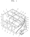
- Figures 1 and 2 are a block diagram and a mimetic diagram showing the construction of the unitary air-conditioner based on the prior art.
- the unitary air-conditioner based on the conventional art is comprised of: an outdoor unit 1 installed to be fixed on the outside of a building (e.g., a second-story house (Z2)); an indoor unit 2 connected to the outdoor unit 1 through a refrigerant pipe and mounted to be fixed in a basement or on a wall of the building, for supplying cold or hot blast in the building; an inlet duct 3 and an outlet duct 4 connected to an inlet port and outlet port of the indoor unit 2, respectively, and installed on walls of each story of the building to be separated; and zone controllers 5a ⁇ 5d installed between the inlet duct 3 and the outlet duct 4 and distinguishing an inflow air and an outflow air transferred via the inlet duct 3 and the outlet 4.
- a building e.g., a second-story house (Z2)
- an indoor unit 2 connected to the outdoor unit 1 through a refrigerant pipe and mounted to be fixed in a basement or on a wall of the building, for supplying cold or hot blast in the building
- the outdoor unit 1 is comprised of: a compressor 1 a compressing refrigerant gas; a first heat exchanger 1 b connected to the compressor 1 a through the refrigerant pipe, and condensing the refrigerant gas when the unitary air-conditioner is in a cooling mode and absorbing latent heat when the unitary air-conditioner is in a heating mode; an expansion valve 1 c decreasing a pressure of the refrigerant gas or expanding the refrigerant gas; and an outdoor fan (not shown) supplying an external air to the first heat exchanger 1 b to raise a heat exchanging efficiency of the first heat exchanger 1 b.
- the indoor unit 2 is comprised of: a second heat exchanger 2A connected to the first heat exchanger 1 b and the expansion valve 1 c; and an indoor fan (not shown) placed at the second heat exchanger 2A, for inducing cool blast or hot blast to the inlet duct 3.
- the inlet duct 3 and the outlet duct 4 are connected to the inlet port and the outlet port of the indoor unit 2 and mounted on corresponding zones (e.g., a first floor (Z1), a second floor (Z2), etc). Also, the inlet duct 3 and the outlet duct 4 respectively have a discharge opening 3a supplying cold blast or hot blast to a corresponding zone and a suction opening 4a sucking indoor air to circulate the indoor air.
- the zone controllers 5a ⁇ 5d are valves mounted on the inlet duct 3 and the outlet duct 4 installed in corresponding zones (e.g., Z1 and Z2) in order to supply cold blast or hot blast to the corresponding zones (Z1 and Z2). That is, the zone controller 5a ⁇ 5d are electrically connected to a controller (not shown) of the unitary air-conditioner, and the controller detects a temperature or a humidity of corresponding zones, compares the detected value of the temperature or the humidity with a predetermined value, and controls the zone controllers 5a ⁇ 5d to be turned on/off according to the compared result.
- a controller not shown
- Figures 3A and 3B are schematic diagrams showing a construction of a unitary air-conditioner based on the prior art.
- the unitary air-conditioner is comprised of a single stage thermostat 11 for detecting an indoor temperature, a single stage indoor unit 12 and a single stage outdoor unit 13.
- the unitary air-conditioner is comprised of a two-stage thermostat 21 for detecting the indoor temperature, a two-stage indoor unit 22 and a two-stage outdoor unit 23.
- the single stage indoor unit 12 refers to an indoor unit for rotating an indoor fan installed therein at a predetermined speed (e.g., an intermediate speed).
- the single stage outdoor unit 13 refers to an outdoor unit for on-off controlling only one compressor installed therein.
- the two-stage indoor unit 22 refers to an indoor unit for rotating the indoor fan installed therein at a high speed or a low speed.
- the two-stage outdoor unit 23 refers to an outdoor unit for on-off controlling only a small compression capacity compressor, of the small compression capacity compressor and a large compression capacity compressor, or simultaneously on- off controlling both the two compressors.
- the unitary air-conditioner based on the conventional art is comprised of a single stage thermostat 11, a single stage indoor unit 12 and a single stage outdoor unit 13, of which operation will be described with reference to Figure 4, hereinafter.
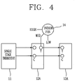
- Figure 4 is a schematic diagram showing a flow of a control signal in a unitary air-conditioner based on the prior art.
- the unitary air-conditioner based on the conventional art is comprised of a single stage thermostat 11, a single stage indoor unit 12 and a single stage outdoor unit 13, the single stage thermostat 11 generates a driving signal on the basis of an indoor temperature and a temperature predetermined by a user, and outputs the generated driving signal to a terminal 12A of the single stage indoor unit 12.
- the single stage indoor unit 12 converts the driving signal into a single stage control signal (Y signal) for driving an indoor fan 14 and a compressor of the single stage outdoor unit 13, and outputs the converted single stage control signal to a terminal (Y terminal) 13A of the single stage outdoor unit 13.
- the unitary air-conditioner based on the conventional art rotates the indoor fan 14 of the single stage indoor unit 12 only at an intermediate speed and operates one compressor of the single stage outdoor unit 13.
- "C" in Figure 4 indicates a common terminal.
- the air-conditioner according to the conventional art was driven only when using an outdoor unit which corresponds to the number of driving stage of an indoor unit. That is, there was a problem that the single stage indoor unit could not be connected to the two-stage outdoor unit for use. For instance, in order to allow a user to save his/her costs and improve efficiency of the outdoor unit, the conventional single stage indoor unit could not be connected to the two-stage outdoor unit.
- an object of the present invention is to provide an air-conditioner capable of connecting a single stage indoor unit to a two-stage outdoor unit, and of improving an ability thereof corresponding to a heating load or a cooling load, and a method for controlling a driving thereof.
- an air-conditioner comprising a converter which receives a first control signal for on-off controlling an indoor fan of an indoor unit and a compressor of an outdoor unit in the air-conditioner, and generates a second control signal for rotating the indoor fan at a high or low speed and varying a compression capacity of the compressor in the outdoor unit on the basis of a generation time of the received first control signal.
- an air-conditioner comprising: an indoor fan; an outdoor unit having at least one or more compressors driven with respectively different compression capacities; an indoor unit for generating a first control signal to on-off control the indoor fan and the compressor of the outdoor unit, depending on an indoor temperature and a temperature predetermined by a user; and a converter for generating a second control signal to rotate the indoor fan at a high or a low speed and to vary a compression capacity of the outdoor unit, depending on a generation time of the first control signal.
- an air-conditioner comprising: an indoor fan rotated at a high or a low speed on the basis of a two-stage control signal; a two-stage outdoor unit for driving internal compressors with a small compression capacity or a large compression capacity on the basis of the two-stage control signal; a single stage thermostat for generating a driving signal on the basis of an indoor temperature and a temperature predetermined by a user; a single stage indoor unit for generating a single stage control signal for on-off controlling the indoor fan and the compressors, depending on the driving signal; and a converter for generating a two-stage control signal to rotate the indoor fan at a high or a low speed and to vary a compression capacity of the two-stage outdoor unit, depending on a generation time of the single stage control signal, and for outputting the two-stage control signal to the indoor fan and the two-stage outdoor unit.
- a method for controlling a driving of an air-conditioner comprising the steps of: receiving a first control signal for on-off controlling an indoor fan of an indoor unit and a compressor of an outdoor unit in the air-conditioner, measuring a generation time of the received first control signal; and rotating the indoor fan at a high or a low speed and varying a compression capacity of the compressor of the outdoor unit, depending on the measured generation time.
- a method for controlling a driving of an air-conditioner comprising the steps of: generating a first control signal for on-off controlling an indoor fan and an indoor unit, depending on an indoor temperature and a temperature predetermined by a user; measuring a generation time of the first control signal; comparing the measured time with a predetermined reference time; and generating a second control signal for rotating the indoor fan at a high or a low speed and varying a compression capacity of an outdoor unit, depending on the compared result.
- an air-conditioner and a method for controlling a driving thereof capable of connecting a single stage indoor unit to a two-stage outdoor unit and of improving an ability thereof corresponding to a heating load or a cooling load, by receiving a first control signal for on-off controlling an indoor fan of an indoor unit and a compressor of an outdoor unit in the air-conditioner, and generating a second control signal for rotating the indoor fan at a high or a low speed and varying a compression capacity of the compressor in the outdoor unit, depending on a generation time of the received first control signal.
- Figure 5A is a schematic diagram showing a construction of an air-conditioner in accordance with an embodiment of the present invention.
- the air-conditioner according to the present invention is comprised of: a single stage thermostat 31, a single stage indoor unit 32 and a two-stage outdoor unit 33.
- the two-stage outdoor unit 33 may be comprised of a small compression capacity compressor (not shown) and a large compression capacity compressor (not shown), or comprised of one compressor (not shown) of which compression capacity can be varied.
- FIG. 5B is a block diagram showing a detailed construction of the air-conditioner in accordance with an embodiment of the present invention.
- the air-conditioner in accordance with an embodiment of the present invention is comprised of: an indoor fan 35 rotated at a high or a low speed on the basis of a two-stage control signal; a two-stage outdoor unit 33 for receiving the two-stage control signal through an outdoor unit terminal 33A, and for driving a compressor with a small compression capacity or a large compression capacity on the basis of the received two-stage control signal; a single stage thermostat 31 for detecting an indoor temperature and generating a driving signal based on the detected indoor temperature and a desired temperature predetermined by a user; a single stage indoor unit 32 for receiving the driving signal through an indoor terminal 32A, and generating a single stage control signal for on-off controlling the indoor fan 35 and the compressor, depending on the received driving signal; a converter 34 for converting the single stage control signal into a two-stage control signal (e.g., Y1 and Y2) to rotate the indoor fan 35 at a high or a low speed and to vary the compression capacity of
- the air-conditioner drives only the small compression capacity compressor, or drives both the small compression capacity compressor and the large compression capacity compressor at the same time.
- the indoor fan 35 is rotated at a low speed when only the small compression capacity compressor of the two-stage outdoor unit 33 is driven, while the indoor fan 35 is rotated at a high speed when both the small compression capacity compressor and the large compression capacity compressor of the two-stage outdoor unit 33 are driven at the same time.
- the converter 34 can be implemented as a microprocessor which detects a generation time of the single stage control signal, compares the generation time with a predetermined reference time, and converts the single stage control signal to the two-stage control signal (i.e., a first control signal Y1 and a second control signal Y2), depending on the compared result.
- the first control signal Y1 refers to a signal for driving only the small compression capacity compressor of the two-stage outdoor unit 33 and rotating the indoor fan 35 at a low speed.
- the second control signal Y2 refers to a signal for simultaneously driving both the small compression capacity compressor and the large compression capacity compressor of the two-stage outdoor unit 33 and for rotating the indoor fan 35 at a high speed.
- the converter 34 measures a generation time of the single stage control signal and at the same time generates a first control signal for driving only the small compression capacity compressor of the two-stage outdoor unit 33 and rotating the indoor fan 35 at a low speed. Thereafter, the converter 34 outputs the generated first control signal to the indoor fan 35 and the two-stage outdoor unit 33. If the single stage control signal is generated after a predetermined reference time (e.g., 10 minutes) elapses, the converter 34 generates a second control signal for simultaneously driving the small compression capacity compressor and the large compression capacity compressor of the two-stage outdoor unit 33 and for rotating the indoor fan 35 at a high speed, and then outputs the generated second control signal to the indoor fan 35 and the two-stage outdoor unit 33. If the single stage control signal is generated after a predetermined limitation time (e.g., one hour) elapses, the converter 34 generates the second control signal and outputs the generated second control signal to the indoor fan 35 and the two-stage outdoor unit 33.
- a predetermined reference time e.g. 10 minutes
- Figure 6 is a flow chart showing a method for controlling a driving a unitary air-conditioner in accordance with an embodiment of the present invention.
- the single stage thermostat 31 detects an indoor temperature (S1), compares the detected indoor temperature and a desired temperature predetermined by a user. Thereafter, the single stage thermostat 31 generates a driving signal based on the compared result, and then outputs the generated driving signal to the single stage indoor unit 32.
- the single stage indoor unit 32 generates a single stage control signal Y for on-off controlling the indoor fan 35 and the compressor on the basis of the driving signal (S2).
- operations of the single stage thermostat 31 and the single stage indoor unit 32 are same as operations in the conventional art, of which explanation will be thus omitted.
- the converter 34 measures a generation time of the single stage control signal Y (S3) and at the same time generates the first control signal Y1 for driving only the small compression capacity compressor of the two-stage outdoor unit 33 and rotating the indoor fan 35 at a low speed.
- the converter 34 thereafter outputs the generated first control signal Y1 to the indoor fan 35 and the two-stage outdoor unit 33.
- the indoor fan 35 supplies cold blast or hot blast indoors by being rotated at a low speed on the basis of the first control signal, and the two-stage outdoor unit 33 drives only the small compression capacity compressor, depending on the first control signal.
- the converter 34 generates the second control signal Y2 for simultaneously driving the small compression capacity compressor and the large compression capacity compressor of the two-stage outdoor unit 33 and for rotating the indoor fan 35 at a high speed, and then outputs the generated second control signal to the indoor fan 35 and the two-stage outdoor unit 33.
- the indoor fan 35 is rotated at a high speed based on the second control signal, and the two-stage outdoor unit 33 drives the small compression capacity compressor and the large compression capacity compressor at the same time, on the basis of the second control signal.
- the converter 34 generates the second control signal and outputs the generated second control signal to the indoor fan 35 and the two-stage outdoor unit 33.
- the indoor fan 35 is rotated at a high speed based on the second control signal, and the two-stage outdoor unit 33 drives the small compression capacity compressor and the large compression capacity compressor simultaneously on the basis of the second control signal. That is, if the single stage control signal is generated after the predetermined limitation time (e.g., one hour) elapses, the converter 34 outputs the second control signal to the indoor fan 35 and the two-stage outdoor unit 33 for cooling or heating the indoor room rapidly.
- the predetermined limitation time e.g., one hour
- the single stage indoor unit can be connected to the two-stage outdoor unit by converting the single stage control signal into the two-stage control signal, depending on the generation time of the single stage control signal.
- the costs to purchase the two-stage indoor unit can be effectively reduced by converting the single stage control signal into the two-stage control signal, depending on the generation time of the single stage control signal.
Landscapes
- Engineering & Computer Science (AREA)
- General Engineering & Computer Science (AREA)
- Chemical & Material Sciences (AREA)
- Combustion & Propulsion (AREA)
- Mechanical Engineering (AREA)
- Physics & Mathematics (AREA)
- Signal Processing (AREA)
- Fluid Mechanics (AREA)
- Fuzzy Systems (AREA)
- Mathematical Physics (AREA)
- Human Computer Interaction (AREA)
- Thermal Sciences (AREA)
- Air Conditioning Control Device (AREA)
Applications Claiming Priority (1)
| Application Number | Priority Date | Filing Date | Title |
|---|---|---|---|
| KR1020040066065A KR100608685B1 (ko) | 2004-08-20 | 2004-08-20 | 유니터리 공기조화기 및 그의 운전제어방법 |
Publications (3)
| Publication Number | Publication Date |
|---|---|
| EP1632737A2 true EP1632737A2 (de) | 2006-03-08 |
| EP1632737A3 EP1632737A3 (de) | 2007-08-15 |
| EP1632737B1 EP1632737B1 (de) | 2010-12-08 |
Family
ID=36080325
Family Applications (1)
| Application Number | Title | Priority Date | Filing Date |
|---|---|---|---|
| EP05005924A Expired - Lifetime EP1632737B1 (de) | 2004-08-20 | 2005-03-18 | Klimaanlage und Verfahren zum Steuern ihres Antriebes |
Country Status (5)
| Country | Link |
|---|---|
| US (1) | US20060037332A1 (de) |
| EP (1) | EP1632737B1 (de) |
| KR (1) | KR100608685B1 (de) |
| CN (1) | CN1737440A (de) |
| DE (1) | DE602005025182D1 (de) |
Cited By (1)
| Publication number | Priority date | Publication date | Assignee | Title |
|---|---|---|---|---|
| EP2056033A1 (de) * | 2007-10-31 | 2009-05-06 | LG Electronics Inc. | Verfahren zum Steuern des Motors einer Klimaanlage und Motorsteuerung dafür |
Families Citing this family (16)
| Publication number | Priority date | Publication date | Assignee | Title |
|---|---|---|---|---|
| EP1740401B1 (de) * | 2004-04-19 | 2009-08-19 | Behr GmbH & Co. KG | Verfahren und vorrichtung zur regelung eines kältemittelkreislaufs einer klimaanlage für ein fahrzeug |
| KR100697195B1 (ko) * | 2004-12-28 | 2007-03-21 | 엘지전자 주식회사 | 유니터리 에어컨 및 그것의 가변 운전 제어 방법 |
| KR100697196B1 (ko) * | 2004-12-28 | 2007-03-21 | 엘지전자 주식회사 | 유니터리 에어컨의 압축기 급속 온오프 방지 제어 방법 |
| KR100624790B1 (ko) * | 2004-12-30 | 2006-09-19 | 엘지전자 주식회사 | 유니터리 에어컨 |
| US8156751B2 (en) * | 2005-05-24 | 2012-04-17 | Emerson Climate Technologies, Inc. | Control and protection system for a variable capacity compressor |
| CN101900453A (zh) * | 2009-05-27 | 2010-12-01 | 王春刚 | 一种热泵空调地暖系统 |
| US9709311B2 (en) | 2015-04-27 | 2017-07-18 | Emerson Climate Technologies, Inc. | System and method of controlling a variable-capacity compressor |
| US10197319B2 (en) | 2015-04-27 | 2019-02-05 | Emerson Climate Technologies, Inc. | System and method of controlling a variable-capacity compressor |
| US9562710B2 (en) | 2015-04-27 | 2017-02-07 | Emerson Climate Technologies, Inc. | Diagnostics for variable-capacity compressor control systems and methods |
| CN105241021B (zh) | 2015-10-28 | 2018-07-31 | 华为技术有限公司 | 一种房间级空调调节方法、装置及控制器 |
| US10408517B2 (en) * | 2016-03-16 | 2019-09-10 | Emerson Climate Technologies, Inc. | System and method of controlling a variable-capacity compressor and a variable speed fan using a two-stage thermostat |
| US10760814B2 (en) | 2016-05-27 | 2020-09-01 | Emerson Climate Technologies, Inc. | Variable-capacity compressor controller with two-wire configuration |
| CN106642571B (zh) * | 2016-12-16 | 2019-08-06 | 广东美的制冷设备有限公司 | 室内风机的转速控制方法及装置、空调器 |
| US11429122B2 (en) * | 2017-06-21 | 2022-08-30 | Johnson Controls Tyco IP Holdings LLP | Single zone variable air volume control systems and methods |
| CN110398037B (zh) * | 2019-07-26 | 2021-03-19 | 广东美的暖通设备有限公司 | 风机信号处理方法、空调器及存储介质 |
| US11644213B2 (en) * | 2021-03-26 | 2023-05-09 | Johnson Controls Tyco IP Holdings LLP | Systems and methods to operate HVAC system in variable operating mode |
Family Cites Families (12)
| Publication number | Priority date | Publication date | Assignee | Title |
|---|---|---|---|---|
| JPH03241260A (ja) * | 1990-02-16 | 1991-10-28 | Matsushita Refrig Co Ltd | 多室型空気調和機 |
| US5123256A (en) * | 1991-05-07 | 1992-06-23 | American Standard Inc. | Method of compressor staging for a multi-compressor refrigeration system |
| US5303561A (en) * | 1992-10-14 | 1994-04-19 | Copeland Corporation | Control system for heat pump having humidity responsive variable speed fan |
| GB2272080B (en) * | 1992-10-28 | 1996-01-10 | Toshiba Kk | Air conditioning apparatus capable of operating in cooling mode and heating mode |
| JP3198859B2 (ja) * | 1995-02-14 | 2001-08-13 | ダイキン工業株式会社 | マルチ型空気調和機 |
| JPH08219491A (ja) * | 1995-02-16 | 1996-08-30 | Matsushita Seiko Co Ltd | 熱交換気空調ユニット |
| JP4327331B2 (ja) * | 2000-04-21 | 2009-09-09 | サンデン株式会社 | 車両空調装置用可変容量斜板式圧縮機の制御装置 |
| KR20020073861A (ko) * | 2001-03-16 | 2002-09-28 | 주식회사 센추리 | 멀티형 공기조화 시스템 |
| KR100396849B1 (ko) * | 2001-03-26 | 2003-09-03 | 엘지전자 주식회사 | 멀티 컴프레서가 적용된 공기 조화기의 제어 방법 |
| US6397610B1 (en) * | 2001-05-01 | 2002-06-04 | Cohand Technology Co., Ltd. | Method for controlling air conditioner/heater by coil temperature |
| KR100512278B1 (ko) * | 2002-09-10 | 2005-09-02 | 엘지전자 주식회사 | 냉난방기의 제습 절전 운전방법 |
| KR100465723B1 (ko) * | 2002-12-20 | 2005-01-13 | 엘지전자 주식회사 | 공기조화기의 냉방 운전 방법 |
-
2004
- 2004-08-20 KR KR1020040066065A patent/KR100608685B1/ko not_active Expired - Fee Related
-
2005
- 2005-01-05 US US11/028,631 patent/US20060037332A1/en not_active Abandoned
- 2005-01-24 CN CNA2005100056489A patent/CN1737440A/zh active Pending
- 2005-03-18 DE DE602005025182T patent/DE602005025182D1/de not_active Expired - Lifetime
- 2005-03-18 EP EP05005924A patent/EP1632737B1/de not_active Expired - Lifetime
Cited By (2)
| Publication number | Priority date | Publication date | Assignee | Title |
|---|---|---|---|---|
| EP2056033A1 (de) * | 2007-10-31 | 2009-05-06 | LG Electronics Inc. | Verfahren zum Steuern des Motors einer Klimaanlage und Motorsteuerung dafür |
| US8234879B2 (en) | 2007-10-31 | 2012-08-07 | Lg Electronics Inc. | Method for controlling motor of air conditioner and motor controller of the same |
Also Published As
| Publication number | Publication date |
|---|---|
| EP1632737B1 (de) | 2010-12-08 |
| US20060037332A1 (en) | 2006-02-23 |
| DE602005025182D1 (de) | 2011-01-20 |
| CN1737440A (zh) | 2006-02-22 |
| KR100608685B1 (ko) | 2006-08-08 |
| KR20060017403A (ko) | 2006-02-23 |
| EP1632737A3 (de) | 2007-08-15 |
Similar Documents
| Publication | Publication Date | Title |
|---|---|---|
| EP1605214A2 (de) | Vorrichtung und Verfahren zum Betreiben einer Klimaanlage | |
| EP1632737B1 (de) | Klimaanlage und Verfahren zum Steuern ihres Antriebes | |
| KR100661919B1 (ko) | 유니터리 공기조화기의 운전제어방법 | |
| EP1598606A2 (de) | Klimaanlage und Steuerungsverfahren dafür | |
| KR102262245B1 (ko) | 공기조화기 및 그 제어방법 | |
| KR100619733B1 (ko) | 유니터리 공기조화기의 운전제어방법 | |
| KR101151321B1 (ko) | 멀티형 공기조화기 및 그 운전방법 | |
| US20040011064A1 (en) | Heat pump air conditioning system comprising additional heater and method for operating the same | |
| JPH1096545A (ja) | 空気調和機およびその制御方法 | |
| US20060042283A1 (en) | Air-conditioner and controlling method therefor | |
| EP1598605B1 (de) | Klimaeinheitsystem und Betriebssteuereinrichtung dafür | |
| JP7316759B2 (ja) | 空気調和装置及び空気調和システム | |
| KR20100019163A (ko) | 공기조화기 및 그 제어방법 | |
| JP6562139B2 (ja) | 冷凍装置 | |
| KR20090131158A (ko) | 공기조화기 및 그 제어방법 | |
| KR100712928B1 (ko) | 혼합형 유니터리 공기조화장치의 압축기 선택 운전방법 | |
| JP2025152891A (ja) | 連携制御装置、連携制御方法、連携制御プログラム | |
| KR20050086117A (ko) | 멀티 공기조화기의 냉매 제어장치 | |
| KR20050086118A (ko) | 멀티 공기조화기의 냉매 제어장치 | |
| KR20030073353A (ko) | 덕트형 공기 조화기의 제어방법 및 그 장치 |
Legal Events
| Date | Code | Title | Description |
|---|---|---|---|
| PUAI | Public reference made under article 153(3) epc to a published international application that has entered the european phase |
Free format text: ORIGINAL CODE: 0009012 |
|
| AK | Designated contracting states |
Kind code of ref document: A2 Designated state(s): AT BE BG CH CY CZ DE DK EE ES FI FR GB GR HU IE IS IT LI LT LU MC NL PL PT RO SE SI SK TR |
|
| AX | Request for extension of the european patent |
Extension state: AL BA HR LV MK YU |
|
| PUAL | Search report despatched |
Free format text: ORIGINAL CODE: 0009013 |
|
| AK | Designated contracting states |
Kind code of ref document: A3 Designated state(s): AT BE BG CH CY CZ DE DK EE ES FI FR GB GR HU IE IS IT LI LT LU MC NL PL PT RO SE SI SK TR |
|
| AX | Request for extension of the european patent |
Extension state: AL BA HR LV MK YU |
|
| 17P | Request for examination filed |
Effective date: 20071121 |
|
| AKX | Designation fees paid |
Designated state(s): DE FR GB |
|
| 17Q | First examination report despatched |
Effective date: 20080526 |
|
| GRAP | Despatch of communication of intention to grant a patent |
Free format text: ORIGINAL CODE: EPIDOSNIGR1 |
|
| GRAS | Grant fee paid |
Free format text: ORIGINAL CODE: EPIDOSNIGR3 |
|
| GRAA | (expected) grant |
Free format text: ORIGINAL CODE: 0009210 |
|
| AK | Designated contracting states |
Kind code of ref document: B1 Designated state(s): DE FR GB |
|
| REG | Reference to a national code |
Ref country code: GB Ref legal event code: FG4D |
|
| REF | Corresponds to: |
Ref document number: 602005025182 Country of ref document: DE Date of ref document: 20110120 Kind code of ref document: P |
|
| PGFP | Annual fee paid to national office [announced via postgrant information from national office to epo] |
Ref country code: FR Payment date: 20110401 Year of fee payment: 7 |
|
| PLBE | No opposition filed within time limit |
Free format text: ORIGINAL CODE: 0009261 |
|
| STAA | Information on the status of an ep patent application or granted ep patent |
Free format text: STATUS: NO OPPOSITION FILED WITHIN TIME LIMIT |
|
| 26N | No opposition filed |
Effective date: 20110909 |
|
| GBPC | Gb: european patent ceased through non-payment of renewal fee |
Effective date: 20110318 |
|
| REG | Reference to a national code |
Ref country code: DE Ref legal event code: R097 Ref document number: 602005025182 Country of ref document: DE Effective date: 20110909 |
|
| PG25 | Lapsed in a contracting state [announced via postgrant information from national office to epo] |
Ref country code: GB Free format text: LAPSE BECAUSE OF NON-PAYMENT OF DUE FEES Effective date: 20110318 |
|
| REG | Reference to a national code |
Ref country code: FR Ref legal event code: ST Effective date: 20121130 |
|
| PG25 | Lapsed in a contracting state [announced via postgrant information from national office to epo] |
Ref country code: FR Free format text: LAPSE BECAUSE OF NON-PAYMENT OF DUE FEES Effective date: 20120402 |
|
| PGFP | Annual fee paid to national office [announced via postgrant information from national office to epo] |
Ref country code: DE Payment date: 20160212 Year of fee payment: 12 |
|
| REG | Reference to a national code |
Ref country code: DE Ref legal event code: R119 Ref document number: 602005025182 Country of ref document: DE |
|
| PG25 | Lapsed in a contracting state [announced via postgrant information from national office to epo] |
Ref country code: DE Free format text: LAPSE BECAUSE OF NON-PAYMENT OF DUE FEES Effective date: 20171003 |