EP1632979A2 - Drehanoden-Röntgenröhre und Röntgengenerator - Google Patents
Drehanoden-Röntgenröhre und Röntgengenerator Download PDFInfo
- Publication number
- EP1632979A2 EP1632979A2 EP05015470A EP05015470A EP1632979A2 EP 1632979 A2 EP1632979 A2 EP 1632979A2 EP 05015470 A EP05015470 A EP 05015470A EP 05015470 A EP05015470 A EP 05015470A EP 1632979 A2 EP1632979 A2 EP 1632979A2
- Authority
- EP
- European Patent Office
- Prior art keywords
- coolant
- casing
- rotating anode
- passage
- air
- Prior art date
- Legal status (The legal status is an assumption and is not a legal conclusion. Google has not performed a legal analysis and makes no representation as to the accuracy of the status listed.)
- Granted
Links
Images


Classifications
-
- H—ELECTRICITY
- H01—ELECTRIC ELEMENTS
- H01J—ELECTRIC DISCHARGE TUBES OR DISCHARGE LAMPS
- H01J35/00—X-ray tubes
- H01J35/02—Details
- H01J35/04—Electrodes ; Mutual position thereof; Constructional adaptations therefor
- H01J35/08—Anodes; Anti cathodes
- H01J35/10—Rotary anodes; Arrangements for rotating anodes; Cooling rotary anodes
- H01J35/105—Cooling of rotating anodes, e.g. heat emitting layers or structures
- H01J35/106—Active cooling, e.g. fluid flow, heat pipes
-
- H—ELECTRICITY
- H01—ELECTRIC ELEMENTS
- H01J—ELECTRIC DISCHARGE TUBES OR DISCHARGE LAMPS
- H01J35/00—X-ray tubes
- H01J35/02—Details
- H01J35/04—Electrodes ; Mutual position thereof; Constructional adaptations therefor
- H01J35/08—Anodes; Anti cathodes
- H01J35/10—Rotary anodes; Arrangements for rotating anodes; Cooling rotary anodes
- H01J35/101—Arrangements for rotating anodes, e.g. supporting means, means for greasing, means for sealing the axle or means for shielding or protecting the driving
- H01J35/1017—Bearings for rotating anodes
- H01J35/1024—Rolling bearings
-
- H—ELECTRICITY
- H01—ELECTRIC ELEMENTS
- H01J—ELECTRIC DISCHARGE TUBES OR DISCHARGE LAMPS
- H01J35/00—X-ray tubes
- H01J35/02—Details
- H01J35/04—Electrodes ; Mutual position thereof; Constructional adaptations therefor
- H01J35/08—Anodes; Anti cathodes
- H01J35/10—Rotary anodes; Arrangements for rotating anodes; Cooling rotary anodes
- H01J35/105—Cooling of rotating anodes, e.g. heat emitting layers or structures
- H01J35/107—Cooling of the bearing assemblies
-
- H—ELECTRICITY
- H01—ELECTRIC ELEMENTS
- H01J—ELECTRIC DISCHARGE TUBES OR DISCHARGE LAMPS
- H01J2235/00—X-ray tubes
- H01J2235/20—Arrangements for controlling gases within the X-ray tube
Definitions
- the present invention relates to a rotating anode X-ray tube which is capable of coping with the coolant leakage from a rotary seal, the coolant being for cooling the inside of the rotating anode, and also relates to an X-ray generator having such a rotating anode X-ray tube.
- a rotating anode of a rotating anode X-ray tube is cooled at its inside by cooling water. Since the rotating anode is rotated during cooling by the cooling water, its coolant passage must be sealed by a rotary liquid-tight sealing device such as a mechanical seal or an oil seal. The sealing function of the sealing region is maintained by, in general, an elastic force. When the liquid-tight property has been deteriorated because of roughness or wear of the seal surface, water leakage occurs little by little. When the leakage water adheres to parts such as a bearing, an electric brush or a vacuum sealing device, the lifetime of the parts would be shortened disadvantageously.
- a rotating anode X-ray tube includes a vacuum chamber which houses therein a tray arranged below the anode or target.
- the tray can receive leakage water dropped away the anode.
- the water touches the sensor to generate a water leakage signal.
- generation of the electron beam is stopped and a buzzer sounds to call user's attention to water leakage.
- the above-described water leakage sensor has a following problem.
- the water leakage sensor focuses attention on the water leakage dropped away the anode surface into the internal space of the vacuum chamber.
- Such water leakage is supposed to be water leakage from a coolant passage cropping out due to target erosion caused by electron beam collision, or water leakage from a weld joint of the target.
- the above-described water leakage sensor can not cope with water leakage little by little caused by deterioration of a coolant sealing device.
- water leakage from the coolant sealing device occurs, water does not drop away the anode into the vacuum chamber but enters into the internal space of the casing which rotatably supports the rotating anode.
- the lifetime of parts, such as a bearing, an electric brush or a vacuum sealing device, housed in the casing is shortened disadvantageously as has been described above.
- the water leakage sensor disclosed in the second publication can not cope with such water leakage.
- the leakage water little by little from the coolant sealing device is not in the form of liquid but is in the form of fine-atomized droplets or vapor, which may disperses into the internal space of the casing.
- the type of water leakage sensor which stores water in a tray can not always detect such water leakage and can not early detect a trace of water leakage. At the stage of a trace of water leakage, it would be effective to let out water in the form of vapor to the atmosphere to prolong the lifetime of parts, but such a thing is impossible in the prior art disclosed in the second publication.
- a rotating anode X-ray tube comprises: (a) a rotating anode including therein a first coolant passage; (b) an electron gun for irradiating the rotating anode with an electron beam; (c) a vacuum chamber housing therein the rotating anode and the electron gun; (d) a rotary shaft fixed to the rotating anode; (e) a casing which houses therein the rotary shaft and is secured to the vacuum chamber; (f) bearing means arranged between the rotary shaft and the casing so as to rotatably support the rotary shaft; (g) a rotary vacuum sealing device arranged between the rotary shaft and the casing; (h) a second coolant passage formed inside the rotary shaft so as to communicate with the first cool
- the rotating anode X-ray tube may have a coolant sensor communicating with the air passage for detecting water leakage.
- the coolant sensor may detect water in the form of liquid or in the form of vapor.
- One example of the former sensor is a sensor detecting an electric resistance between a pair of electrodes for sensing existence of coolant.
- One example of the latter sensor is a humidity sensor.
- the humidity sensor may consist of: an inlet humidity sensor for sensing a humidity of air entering into the air passage; and an outlet humidity sensor for sensing a humidity of air flowing out of the air passage, so as to determine moisture content caused by the water leakage.
- a rotating anode X-ray tube according to the present invention may omit the rotary vane and may use the coolant sensor only.
- the coolant sensor may be preferably a humidity sensor.
- An X-ray generator is characterized in that it comprises the above-described rotating anode X-ray tube and a high-voltage power supply for supplying a high voltage between the electron gun and the rotating anode.
- the output signal of the coolant sensor may be transferred to the high-voltage power supply to stop the power supply in water leakage.
- a rotating anode X-ray tube has the advantages described below. Air in the air passage formed in the casing is discharged to the atmosphere with the rotary vane, so that the cooling water leaking in the air passage in the form of vapor or atomized droplets can be soon discharged to the atmosphere. Therefore, vapor is prevented from condensing on parts such as a bearing, an electric brush or a vacuum sealing device, housed in the casing to prolong the lifetime of the parts. Further, there is provided a coolant sensor communicating with the air passage in addition to the rotary vane, so as to detect cooling water leaking from the rotary liquid-tight sealing device, to prompt an operator to exchange the rotary fluid-tight sealing device. Additionally, even when the rotary vane is omitted to use only the humidity sensor, a trace of water leakage can be detected.
- Figs. 1 to 3 show the principal part of one embodiment of a rotating anode X-ray tube according the present invention.
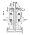
- Fig. 1 is a sectional view taken along a plane including an axis of rotation of a rotating anode, especially showing clearly a coolant passage.
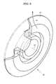
- Fig. 2 is a sectional view taken along another plane including the axis of rotation of the rotating anode, especially showing clearly an air passage.
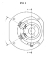
- Fig. 3 is a rear view shown from the right in Fig. 1.
- Fig. 1 is a sectional view taken along the line 1-1 in Fig. 3, while Fig. 2 is a sectional view taken along the line 2-2 in Fig. 3.
- a rotating anode X-ray tube has a vacuum chamber 10, and has a rotating anode 12 and an electron gun 14 each housed in the vacuum chamber 10.
- a high voltage is supplied, from a high-voltage power supply, between the electron gun 14 and the rotating anode 12 to allow the electron gun 14 to generate an electron beam 16.
- Outer peripheral surface of the cylindrical rotating anode 12 is irradiated with the electron beam 16 to generate an X-ray.
- the rotating anode 12 belongs to a rotating anode assembly 18, which is secured to the vacuum chamber 10 to arrange the rotating anode 12 at the predetermined position in the internal space of the vacuum chamber 10.
- the rotating anode assembly 18 has a casing 20 whose flange 22 can be airtightly secured to the vacuum chamber 10.
- the rotating anode 12 is fixed to a rotary shaft 24.
- a magnetic fluid sealing device 26 providing a rotary vacuum seal, ball bearings 28 and 29 for rotatably supporting the rotary shaft 24, an electric brush 30 for discharging a current from the rotary shaft 24 to the casing 20, and a mechanical seal 32 providing a rotary seal for sealing cooling water.
- the magnetic fluid sealing device 26 corresponds to the rotary vacuum sealing device in the present invention.
- the mechanical seal 32 corresponds to the rotary liquid-tight sealing device in the present invention.
- a stator 34 of a direct drive motor To the inner surface of the casing 20 is fixed a stator 34 of a direct drive motor, while to the outer surface of the rotary shaft 24 is fixed a rotor 36 of the direct drive motor.
- the direct drive motor rotates the rotary shaft 24 further to rotate the rotating anode 12.
- first coolant passage 38 which is divided, by a partition plate 39, into the first inflow passage 40 and the first outflow passage 42.
- second coolant passage 44 which is also divided, by a partition pipe 45, into the second inflow passage 46 arranged inside and the second outflow passage 48 arranged outside.
- the partition plate 39 is fixed to the partition pipe 45 whose root, i.e., the right edge in Fig. 1, is fixed to the casing 20.
- the rotating anode 12 and the rotary shaft 24 can be rotated, while the partition plate 39 and the partition pipe 45 disposed therein remain stationary.
- the first inflow passage 40 communicates with the second inflow passage 46, while the first outflow passage 42 communicates with the second outflow passage 48.
- the casing 20 is provided with a coolant inlet 50 and a coolant outlet 52.
- An inlet piping nipple 54 is secured to the coolant inlet 50 while an outlet piping nipple 56 is secured to the coolant outlet 52, see also Fig. 3.
- the cooling water having entered into the coolant inlet 50 is to pass through the second inflow passage 46 and enter into the first inflow passage 40 to cool the internal surface of the rotating anode 12.
- the returning cooling water passes through the first outflow passage 42 and the second outflow passage 48 and flows out of the coolant outlet 52.
- an air passage 60 is formed inside the casing 20 in the vicinity of the backside 58 of the casing 20.
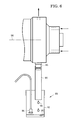
- Fig. 4 which is an enlarged sectional view showing the vicinity of the air passage 60, two air inlets 62 (see also Fig. 3) are formed in the backside 58 of the casing 20.
- one air outlet 64 is formed in the outer peripheral surface of the casing 20.
- the air inlets 62 and the air outlet 64 both communicate with the air passage 60 inside which a rotary vane 66 is disposed.
- the rotary vane 66 is secured to the rotary shaft 24.
- the air outlet 64 is positioned radially outside of the outer periphery of the rotary vane 66, while the air inlets 62 are positioned radially inside of the outer periphery of the rotary vane 66.
- the mechanical seal 32 is arranged between the rotary vane 66 and the casing 20.
- the mechanical seal 32 consists of a rotary ring 68 made of carbon arranged at the rotating-side, and a seat ring 70 made of SiC arranged at the stationary-side.
- the rotary ring 68 is housed in an annular groove formed in the rotary vane 66.
- a rubber sheet 71 is arranged inside the groove so as to push the rotary ring 68 against the seat ring 70 under the elastic force of the rubber sheet 71.
- the rotary ring 68 can be rotated during contact with the seat ring 70 to provide a seal between the cooling water inside the second outflow passage 48 and the air inside the air passage 60.
- An outer race of the ball bearing 29 is correctly positioned axially by a bearing retainer 72, which receives an axial force, i.e., a leftward force in Fig. 4, via a coned disc spring 74 from a coned disc spring retainer 76.
- the rotary vane 66 is provided with a recess 80 which covers a projection 78 of the coned disc spring retainer 76.
- the gap G between the coned disc spring retainer 76 and the rotary vane 66 is 0.3 to 0.5 mm.
- a disc-shaped air guide 67 of the rotary vane 66 lets out the air in the air passage 60 radially outwardly, so that the air flows out of the air outlet 64. Then, since the pressure in the air passage 60 decreases, air enters into the air passage 60 from the air inlet 62. In this manner during rotation of the rotating anode, the atmospheric air outside the casing 20 can circulate in the air passage 60.
- the rotary vane 66 has the disc-shaped air guide 67, which extends, in the sectional shape, in a direction moving away from an axis of rotation 82.
- the air around the air guide 67 is to be rotated along with the air guide due to its viscosity, and further to be let out, due to the centrifugal force, radially outwardly along the air guide 67 as indicated by an arrow 84.
- the air guide 67 may have any shape other than a disc shape, such as a blade for use in a fan.
- the function of the rotary vane 66 will be described.
- the cooling water may leak little by little from the seal surface into the air passage 60.
- the water leaks in the form of fine-atomized droplets or vapor.
- the droplets or vapor adheres to the ball bearing 29 and is condensed thereon.
- the vapor flows, as shown in Fig. 2, toward the electric brush 30, the bearing 28, and the magnetic fluid sealing device 26 and is condensed thereon. In this manner, there is a risk in which the leakage water from the mechanical seal 32 would shorten the lifetime of the various parts in the casing 20.
- the casing 20 is provided with a detection port 84 for detecting leakage water into the air passage 60.
- the detection port 84 communicates with the air passage 60 and is positioned radially outside of the outer periphery of the rotary vane 66.
- a cooling sensor is connected to the detection port 84.
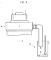
- to the detection port 84 is connected a piping nipple 86, to which the coolant sensor is connected.
- a hose 90 is connected to the piping nipple 86.
- the end of the hose 90 opens in the internal space of a liquid vessel 92.
- Cooling water 94 drops away from the hose 90 to be stored in the liquid vessel 92.
- a liquid leakage sensor 96 operates to generate an output signal representative of the water leakage.
- the liquid leakage sensor 96 can detect an electric resistance between a pair of electrodes for detecting existence of water.
- the output signal is transferred to the high-voltage power supply, resulting in automatic shutdown of the power supply, followed by halt of the rotation of the rotating anode and halt of supply of the cooling water.
- an alarm buzzer may sound or an alarm lamp may turn on to inform an operator of water leakage, so that the operator can exchange the mechanical seal.
- Fig. 7 shows an embodiment in which an attitude of a rotating anode is changed from a horizontal position to the vertical position. That is, the embodiment shown in Fig. 6 has a horizontal axis of rotation 98 of the rotating anode X-ray tube, while the embodiment shown in Fig. 7 has a vertical axis of rotation 98 of the rotating anode X-ray tube.
- the leakage water flow is shown in Fig. 8, which is a sectional view indicating a flow of water leakage in the arrangement shown in Fig. 7. Cooling water 100 leaking from the mechanical seal 32 flows as indicated by an arrow 100 and finally flows out of the piping nipple 86.
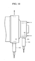
- Fig. 9 is a side view of such an embodiment.
- a humidity sensor 102 which can early detect cooling water leaking in the form of fine-atomized droplets or vapor.
- the sensor used in the embodiment is a combination sensor consisting of a temperature sensor and a humidity sensor.
- one of the air inlets 62 is provided with another detection port 104 for inflow air.
- a humidity sensor 106 for the inflow air the sensor 106 being referred to as an inlet humidity sensor 106.
- a humidity sensor 102 arranged in the outlet-side detection port 84 is referred to as an outlet humidity sensor 102.
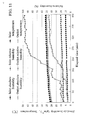
- Fig. 11 is a graph showing humidity variations measured using the inlet humidity sensor and the outlet humidity sensor. Abscissa represents an elapsed time, in minute, during rotation of the rotating anode x-ray tube, the origin of the time scale being a time point at which measurement is commenced with the humidity sensors. A scale on the left ordinate is common to absolute humidity, in gram per cubic meter, and a temperature, in degrees Celsius. A scale on the right ordinate is relative humidity, in percent. The temperature/humidity sensor can detect the relative humidity and the temperature. The absolute humidity can be calculated based on the relative humidity and the temperature. The graph of Fig. 11 indicates measured relative humidity, measured temperatures and calculated absolute humidity.
- Fig. 12 shows further another embodiment of the present invention.
- This embodiment has the rotary vane 66 but no coolant sensor, and accordingly has only the function of discharging cooling water which has leaked from the mechanical seal 32 in the form of atomized droplets or vapor, to the outside along with air.
- This embodiment has two air inlets 62 and two air outlets 64, so that dew condensation on the parts inside the casing is prevented from occurring to prolong the lifetime of the parts.
- the mechanical seal may preferably be exchanged for a new one at regular intervals to lower the risk of water leakage in the form of liquid.
- the present invention may omit the rotary vane in the case of using the humidity sensor as the coolant sensor. That is, in the embodiment shown in Fig. 9 (having one humidity sensor) or shown in Fig. 10 (having two humidity sensors), the rotary vane inside the casing may be omitted. In this case, since there is no function of air circulation caused by the rotary vane, a small air pump may be provided on the outer surface of the casing, so that dry air from the pump may enter into the air inlet of the casing. The air flow rate of the pump may be very small.
- cooling water is used as the coolant in the embodiments described above, any other coolant may be used.
Landscapes
- Physics & Mathematics (AREA)
- Fluid Mechanics (AREA)
- X-Ray Techniques (AREA)
Applications Claiming Priority (1)
| Application Number | Priority Date | Filing Date | Title |
|---|---|---|---|
| JP2004208730A JP3836855B2 (ja) | 2004-07-15 | 2004-07-15 | 回転対陰極x線管及びx線発生装置 |
Publications (3)
| Publication Number | Publication Date |
|---|---|
| EP1632979A2 true EP1632979A2 (de) | 2006-03-08 |
| EP1632979A3 EP1632979A3 (de) | 2006-04-12 |
| EP1632979B1 EP1632979B1 (de) | 2010-09-08 |
Family
ID=35501198
Family Applications (1)
| Application Number | Title | Priority Date | Filing Date |
|---|---|---|---|
| EP05015470A Expired - Lifetime EP1632979B1 (de) | 2004-07-15 | 2005-07-15 | Drehanoden-Röntgenröhre und Röntgengenerator |
Country Status (4)
| Country | Link |
|---|---|
| US (1) | US7197117B2 (de) |
| EP (1) | EP1632979B1 (de) |
| JP (1) | JP3836855B2 (de) |
| DE (1) | DE602005023394D1 (de) |
Families Citing this family (14)
| Publication number | Priority date | Publication date | Assignee | Title |
|---|---|---|---|---|
| US7508916B2 (en) * | 2006-12-08 | 2009-03-24 | General Electric Company | Convectively cooled x-ray tube target and method of making same |
| FR2918501B1 (fr) | 2007-07-02 | 2009-11-06 | Xenocs Soc Par Actions Simplif | Dispositif de delivrance d'un faisceau de rayons x a haute energie |
| JP2009158347A (ja) * | 2007-12-27 | 2009-07-16 | Bruker Axs Kk | X線発生装置 |
| US20100128848A1 (en) * | 2008-11-21 | 2010-05-27 | General Electric Company | X-ray tube having liquid lubricated bearings and liquid cooled target |
| US8009805B2 (en) * | 2009-06-09 | 2011-08-30 | General Electric Company | Rotating union for a liquid cooled rotating X-ray target |
| JP5238646B2 (ja) * | 2009-09-01 | 2013-07-17 | ブルカー・エイエックスエス株式会社 | X線発生装置 |
| JP5113813B2 (ja) * | 2009-09-01 | 2013-01-09 | ブルカー・エイエックスエス株式会社 | X線発生装置 |
| US9300190B2 (en) * | 2011-10-21 | 2016-03-29 | Hamilton Sundstrand Corporation | Free-surface liquid capture device for rotating machinery |
| CN102510653B (zh) * | 2011-11-23 | 2013-12-18 | 丹东奥龙射线仪器集团有限公司 | 工业x射线探伤机水冷却装置 |
| JP6677420B2 (ja) | 2016-04-01 | 2020-04-08 | キヤノン電子管デバイス株式会社 | X線管装置 |
| JP6960153B2 (ja) * | 2017-09-05 | 2021-11-05 | 株式会社リガク | X線発生装置 |
| US11164713B2 (en) * | 2020-03-31 | 2021-11-02 | Energetiq Technology, Inc. | X-ray generation apparatus |
| US11749489B2 (en) | 2020-12-31 | 2023-09-05 | Varex Imaging Corporation | Anodes, cooling systems, and x-ray sources including the same |
| JP7696639B2 (ja) * | 2023-07-11 | 2025-06-23 | 株式会社リガク | 蛍光x線分析装置、蛍光x線分析装置の漏水管理方法、情報記憶媒体及びプログラム |
Family Cites Families (16)
| Publication number | Priority date | Publication date | Assignee | Title |
|---|---|---|---|---|
| US4165472A (en) * | 1978-05-12 | 1979-08-21 | Rockwell International Corporation | Rotating anode x-ray source and cooling technique therefor |
| US4622687A (en) * | 1981-04-02 | 1986-11-11 | Arthur H. Iversen | Liquid cooled anode x-ray tubes |
| US4405876A (en) * | 1981-04-02 | 1983-09-20 | Iversen Arthur H | Liquid cooled anode x-ray tubes |
| US4625324A (en) * | 1983-09-19 | 1986-11-25 | Technicare Corporation | High vacuum rotating anode x-ray tube |
| US5018181A (en) * | 1987-06-02 | 1991-05-21 | Coriolis Corporation | Liquid cooled rotating anodes |
| DE8801941U1 (de) * | 1988-02-15 | 1989-06-15 | Siemens AG, 1000 Berlin und 8000 München | Röntgenröhre |
| US4878235A (en) * | 1988-02-25 | 1989-10-31 | Varian Associates, Inc. | High intensity x-ray source using bellows |
| US4928296A (en) * | 1988-04-04 | 1990-05-22 | General Electric Company | Apparatus for cooling an X-ray device |
| JPH02197098A (ja) | 1989-01-25 | 1990-08-03 | Nippon X-Ray Kk | 水漏れ検出手段を備えたx線発生装置 |
| US5541975A (en) * | 1994-01-07 | 1996-07-30 | Anderson; Weston A. | X-ray tube having rotary anode cooled with high thermal conductivity fluid |
| JP3659508B2 (ja) | 1994-01-28 | 2005-06-15 | 株式会社リガク | 回転対陰極型x線発生装置 |
| US5737387A (en) * | 1994-03-11 | 1998-04-07 | Arch Development Corporation | Cooling for a rotating anode X-ray tube |
| JP4298026B2 (ja) * | 1998-11-27 | 2009-07-15 | 株式会社東芝 | X線管装置 |
| US6361208B1 (en) * | 1999-11-26 | 2002-03-26 | Varian Medical Systems | Mammography x-ray tube having an integral housing assembly |
| US6304631B1 (en) * | 1999-12-27 | 2001-10-16 | General Electric Company | X-ray tube vapor chamber target |
| US6430260B1 (en) * | 2000-12-29 | 2002-08-06 | General Electric Company | X-ray tube anode cooling device and systems incorporating same |
-
2004
- 2004-07-15 JP JP2004208730A patent/JP3836855B2/ja not_active Expired - Fee Related
-
2005
- 2005-07-13 US US11/180,190 patent/US7197117B2/en not_active Expired - Lifetime
- 2005-07-15 EP EP05015470A patent/EP1632979B1/de not_active Expired - Lifetime
- 2005-07-15 DE DE602005023394T patent/DE602005023394D1/de not_active Expired - Lifetime
Non-Patent Citations (1)
| Title |
|---|
| None |
Also Published As
| Publication number | Publication date |
|---|---|
| EP1632979A3 (de) | 2006-04-12 |
| JP3836855B2 (ja) | 2006-10-25 |
| US20060013364A1 (en) | 2006-01-19 |
| EP1632979B1 (de) | 2010-09-08 |
| JP2006032099A (ja) | 2006-02-02 |
| DE602005023394D1 (de) | 2010-10-21 |
| US7197117B2 (en) | 2007-03-27 |
Similar Documents
| Publication | Publication Date | Title |
|---|---|---|
| EP1632979B1 (de) | Drehanoden-Röntgenröhre und Röntgengenerator | |
| US4838763A (en) | Canned motor pump | |
| KR100485414B1 (ko) | 베어링 마모 지시기가 있는 로터리 펌프 | |
| US6722854B2 (en) | Canned pump with ultrasonic bubble detector | |
| JP2636097B2 (ja) | 浸漬型電動ポンプにおけるスラスト軸受の摩耗量の監視装置 | |
| KR102281117B1 (ko) | 터보 압축기 | |
| JP2018197668A (ja) | 潤滑剤劣化状態評価方法、潤滑剤劣化検出装置 | |
| KR101036437B1 (ko) | 공랭식 수중펌프 | |
| US20210363989A1 (en) | Machine for depressurizing or compressing gaseous media | |
| KR102078830B1 (ko) | 모듈형 누수 격실을 갖는 수중펌프 | |
| KR20040036685A (ko) | 밀폐식 메커니컬 부스터 | |
| JP2008240655A (ja) | ポンプの羽根車構造 | |
| JP6884440B1 (ja) | マグネットポンプ | |
| EP1809906B1 (de) | Pumpenzweitdichtung | |
| CN111384822B (zh) | 全封闭式旋转电机以及泄漏液检测构造 | |
| JP2696070B2 (ja) | 血液ポンプ | |
| US11664700B2 (en) | Canned motor device | |
| JP7441035B2 (ja) | マグネットポンプ | |
| TW202346711A (zh) | 具有漏水偵測之真空泵總成 | |
| JP2023052353A (ja) | メカニカルシール及びポンプ装置 | |
| JP3232493B2 (ja) | 軸封装置 | |
| JP2020094496A (ja) | 遠心ポンプ | |
| US12442378B2 (en) | Impeller and method for operating an impeller | |
| CN103683671A (zh) | 旋转电机和止回阀装置 | |
| WO2025051438A1 (en) | A shaft sealing device |
Legal Events
| Date | Code | Title | Description |
|---|---|---|---|
| PUAI | Public reference made under article 153(3) epc to a published international application that has entered the european phase |
Free format text: ORIGINAL CODE: 0009012 |
|
| PUAL | Search report despatched |
Free format text: ORIGINAL CODE: 0009013 |
|
| AK | Designated contracting states |
Kind code of ref document: A2 Designated state(s): AT BE BG CH CY CZ DE DK EE ES FI FR GB GR HU IE IS IT LI LT LU LV MC NL PL PT RO SE SI SK TR |
|
| AX | Request for extension of the european patent |
Extension state: AL BA HR MK YU |
|
| AK | Designated contracting states |
Kind code of ref document: A3 Designated state(s): AT BE BG CH CY CZ DE DK EE ES FI FR GB GR HU IE IS IT LI LT LU LV MC NL PL PT RO SE SI SK TR |
|
| AX | Request for extension of the european patent |
Extension state: AL BA HR MK YU |
|
| 17P | Request for examination filed |
Effective date: 20061010 |
|
| AKX | Designation fees paid |
Designated state(s): DE |
|
| GRAP | Despatch of communication of intention to grant a patent |
Free format text: ORIGINAL CODE: EPIDOSNIGR1 |
|
| GRAS | Grant fee paid |
Free format text: ORIGINAL CODE: EPIDOSNIGR3 |
|
| GRAA | (expected) grant |
Free format text: ORIGINAL CODE: 0009210 |
|
| AK | Designated contracting states |
Kind code of ref document: B1 Designated state(s): DE |
|
| REF | Corresponds to: |
Ref document number: 602005023394 Country of ref document: DE Date of ref document: 20101021 Kind code of ref document: P |
|
| PLBE | No opposition filed within time limit |
Free format text: ORIGINAL CODE: 0009261 |
|
| STAA | Information on the status of an ep patent application or granted ep patent |
Free format text: STATUS: NO OPPOSITION FILED WITHIN TIME LIMIT |
|
| 26N | No opposition filed |
Effective date: 20110609 |
|
| REG | Reference to a national code |
Ref country code: DE Ref legal event code: R097 Ref document number: 602005023394 Country of ref document: DE Effective date: 20110609 |
|
| PGFP | Annual fee paid to national office [announced via postgrant information from national office to epo] |
Ref country code: DE Payment date: 20240719 Year of fee payment: 20 |
|
| REG | Reference to a national code |
Ref country code: DE Ref legal event code: R071 Ref document number: 602005023394 Country of ref document: DE |