EP1632985A1 - lampe à decharge haute pression - Google Patents
lampe à decharge haute pression Download PDFInfo
- Publication number
- EP1632985A1 EP1632985A1 EP05017122A EP05017122A EP1632985A1 EP 1632985 A1 EP1632985 A1 EP 1632985A1 EP 05017122 A EP05017122 A EP 05017122A EP 05017122 A EP05017122 A EP 05017122A EP 1632985 A1 EP1632985 A1 EP 1632985A1
- Authority
- EP
- European Patent Office
- Prior art keywords
- coating
- discharge
- discharge vessel
- pressure discharge
- discharge lamp
- Prior art date
- Legal status (The legal status is an assumption and is not a legal conclusion. Google has not performed a legal analysis and makes no representation as to the accuracy of the status listed.)
- Granted
Links
- 239000011248 coating agent Substances 0.000 claims abstract description 59
- 238000000576 coating method Methods 0.000 claims abstract description 59
- 230000008878 coupling Effects 0.000 claims abstract description 5
- 238000010168 coupling process Methods 0.000 claims abstract description 5
- 238000005859 coupling reaction Methods 0.000 claims abstract description 5
- 239000007789 gas Substances 0.000 claims description 15
- ZOKXTWBITQBERF-UHFFFAOYSA-N Molybdenum Chemical compound [Mo] ZOKXTWBITQBERF-UHFFFAOYSA-N 0.000 claims description 9
- 239000011888 foil Substances 0.000 claims description 9
- 229910052750 molybdenum Inorganic materials 0.000 claims description 9
- 239000011733 molybdenum Substances 0.000 claims description 9
- QVGXLLKOCUKJST-UHFFFAOYSA-N atomic oxygen Chemical compound [O] QVGXLLKOCUKJST-UHFFFAOYSA-N 0.000 claims description 8
- 229910052760 oxygen Inorganic materials 0.000 claims description 8
- 239000001301 oxygen Substances 0.000 claims description 8
- XOLBLPGZBRYERU-UHFFFAOYSA-N tin dioxide Chemical compound O=[Sn]=O XOLBLPGZBRYERU-UHFFFAOYSA-N 0.000 claims description 8
- 229910001887 tin oxide Inorganic materials 0.000 claims description 8
- IJGRMHOSHXDMSA-UHFFFAOYSA-N Atomic nitrogen Chemical compound N#N IJGRMHOSHXDMSA-UHFFFAOYSA-N 0.000 claims description 6
- 239000000463 material Substances 0.000 claims description 6
- 239000011261 inert gas Substances 0.000 claims description 5
- 229910052757 nitrogen Inorganic materials 0.000 claims description 3
- 239000012799 electrically-conductive coating Substances 0.000 abstract description 7
- 229910001507 metal halide Inorganic materials 0.000 description 9
- 150000005309 metal halides Chemical class 0.000 description 9
- 230000015556 catabolic process Effects 0.000 description 7
- 238000004519 manufacturing process Methods 0.000 description 6
- VYPSYNLAJGMNEJ-UHFFFAOYSA-N Silicium dioxide Chemical compound O=[Si]=O VYPSYNLAJGMNEJ-UHFFFAOYSA-N 0.000 description 4
- 239000003990 capacitor Substances 0.000 description 4
- 229910052756 noble gas Inorganic materials 0.000 description 4
- 230000004907 flux Effects 0.000 description 3
- 239000011521 glass Substances 0.000 description 3
- 238000010438 heat treatment Methods 0.000 description 3
- 230000005855 radiation Effects 0.000 description 3
- CURLTUGMZLYLDI-UHFFFAOYSA-N Carbon dioxide Chemical compound O=C=O CURLTUGMZLYLDI-UHFFFAOYSA-N 0.000 description 2
- 238000009792 diffusion process Methods 0.000 description 2
- QSHDDOUJBYECFT-UHFFFAOYSA-N mercury Chemical compound [Hg] QSHDDOUJBYECFT-UHFFFAOYSA-N 0.000 description 2
- 229910052753 mercury Inorganic materials 0.000 description 2
- 239000000203 mixture Substances 0.000 description 2
- 238000007789 sealing Methods 0.000 description 2
- ZOXJGFHDIHLPTG-UHFFFAOYSA-N Boron Chemical compound [B] ZOXJGFHDIHLPTG-UHFFFAOYSA-N 0.000 description 1
- PXGOKWXKJXAPGV-UHFFFAOYSA-N Fluorine Chemical compound FF PXGOKWXKJXAPGV-UHFFFAOYSA-N 0.000 description 1
- DGAQECJNVWCQMB-PUAWFVPOSA-M Ilexoside XXIX Chemical compound C[C@@H]1CC[C@@]2(CC[C@@]3(C(=CC[C@H]4[C@]3(CC[C@@H]5[C@@]4(CC[C@@H](C5(C)C)OS(=O)(=O)[O-])C)C)[C@@H]2[C@]1(C)O)C)C(=O)O[C@H]6[C@@H]([C@H]([C@@H]([C@H](O6)CO)O)O)O.[Na+] DGAQECJNVWCQMB-PUAWFVPOSA-M 0.000 description 1
- HCHKCACWOHOZIP-UHFFFAOYSA-N Zinc Chemical compound [Zn] HCHKCACWOHOZIP-UHFFFAOYSA-N 0.000 description 1
- 239000006096 absorbing agent Substances 0.000 description 1
- 230000002411 adverse Effects 0.000 description 1
- 229910052787 antimony Inorganic materials 0.000 description 1
- WATWJIUSRGPENY-UHFFFAOYSA-N antimony atom Chemical compound [Sb] WATWJIUSRGPENY-UHFFFAOYSA-N 0.000 description 1
- 229910052796 boron Inorganic materials 0.000 description 1
- 229910002092 carbon dioxide Inorganic materials 0.000 description 1
- 239000001569 carbon dioxide Substances 0.000 description 1
- 239000002800 charge carrier Substances 0.000 description 1
- 238000006243 chemical reaction Methods 0.000 description 1
- 239000000567 combustion gas Substances 0.000 description 1
- 239000004020 conductor Substances 0.000 description 1
- 239000000356 contaminant Substances 0.000 description 1
- 230000001419 dependent effect Effects 0.000 description 1
- 239000002019 doping agent Substances 0.000 description 1
- 239000011737 fluorine Substances 0.000 description 1
- 229910052731 fluorine Inorganic materials 0.000 description 1
- 150000004820 halides Chemical class 0.000 description 1
- 229910052738 indium Inorganic materials 0.000 description 1
- APFVFJFRJDLVQX-UHFFFAOYSA-N indium atom Chemical compound [In] APFVFJFRJDLVQX-UHFFFAOYSA-N 0.000 description 1
- 229910003437 indium oxide Inorganic materials 0.000 description 1
- PJXISJQVUVHSOJ-UHFFFAOYSA-N indium(iii) oxide Chemical compound [O-2].[O-2].[O-2].[In+3].[In+3] PJXISJQVUVHSOJ-UHFFFAOYSA-N 0.000 description 1
- AMGQUBHHOARCQH-UHFFFAOYSA-N indium;oxotin Chemical compound [In].[Sn]=O AMGQUBHHOARCQH-UHFFFAOYSA-N 0.000 description 1
- 230000031700 light absorption Effects 0.000 description 1
- 239000000155 melt Substances 0.000 description 1
- 229910052751 metal Inorganic materials 0.000 description 1
- 239000002184 metal Substances 0.000 description 1
- 150000002739 metals Chemical class 0.000 description 1
- 230000003287 optical effect Effects 0.000 description 1
- 230000003647 oxidation Effects 0.000 description 1
- 238000007254 oxidation reaction Methods 0.000 description 1
- 229910052706 scandium Inorganic materials 0.000 description 1
- SIXSYDAISGFNSX-UHFFFAOYSA-N scandium atom Chemical compound [Sc] SIXSYDAISGFNSX-UHFFFAOYSA-N 0.000 description 1
- 229910052708 sodium Inorganic materials 0.000 description 1
- 239000011734 sodium Substances 0.000 description 1
- 239000000126 substance Substances 0.000 description 1
- WFKWXMTUELFFGS-UHFFFAOYSA-N tungsten Chemical compound [W] WFKWXMTUELFFGS-UHFFFAOYSA-N 0.000 description 1
- 229910052721 tungsten Inorganic materials 0.000 description 1
- 239000010937 tungsten Substances 0.000 description 1
- XLYOFNOQVPJJNP-UHFFFAOYSA-N water Chemical compound O XLYOFNOQVPJJNP-UHFFFAOYSA-N 0.000 description 1
- 229910052724 xenon Inorganic materials 0.000 description 1
- FHNFHKCVQCLJFQ-UHFFFAOYSA-N xenon atom Chemical compound [Xe] FHNFHKCVQCLJFQ-UHFFFAOYSA-N 0.000 description 1
- 229910052725 zinc Inorganic materials 0.000 description 1
- 239000011701 zinc Substances 0.000 description 1
Images

Classifications
-
- H—ELECTRICITY
- H01—ELECTRIC ELEMENTS
- H01J—ELECTRIC DISCHARGE TUBES OR DISCHARGE LAMPS
- H01J61/00—Gas-discharge or vapour-discharge lamps
- H01J61/02—Details
- H01J61/04—Electrodes; Screens; Shields
- H01J61/06—Main electrodes
- H01J61/073—Main electrodes for high-pressure discharge lamps
-
- H—ELECTRICITY
- H01—ELECTRIC ELEMENTS
- H01J—ELECTRIC DISCHARGE TUBES OR DISCHARGE LAMPS
- H01J61/00—Gas-discharge or vapour-discharge lamps
- H01J61/02—Details
- H01J61/54—Igniting arrangements, e.g. promoting ionisation for starting
- H01J61/547—Igniting arrangements, e.g. promoting ionisation for starting using an auxiliary electrode outside the vessel
-
- H—ELECTRICITY
- H01—ELECTRIC ELEMENTS
- H01J—ELECTRIC DISCHARGE TUBES OR DISCHARGE LAMPS
- H01J61/00—Gas-discharge or vapour-discharge lamps
- H01J61/02—Details
- H01J61/30—Vessels; Containers
- H01J61/35—Vessels; Containers provided with coatings on the walls thereof; Selection of materials for the coatings
Definitions
- the invention relates to a high-pressure discharge lamp according to the preamble of patent claim 1.
- Such a high-pressure discharge lamp is disclosed, for example, in European patent EP 0 991 107 B1.
- EP 0 991 107 B1 On page 4, in lines 12 to 26 of column 6 of this patent a unilaterally capped high-pressure discharge lamp for a motor vehicle headlight is described which has a surrounded by a glass outer bulb discharge vessel, wherein the outer bulb is provided with a transparent, electrically conductive layer which extends over the entire discharge space of the lamp. This layer is connected to the circuit-internal ground reference potential of the operating device of the high-pressure discharge lamp in order to improve the electromagnetic compatibility of the lamp.
- the high-pressure discharge lamp according to the invention has a light-permeable discharge vessel, an ionizable filling arranged in the discharge space of the discharge vessel and extending into the discharge space of the discharge vessel Electrodes for generating a gas discharge, as well as led out of the discharge vessel power supply to the power supply of the electrodes, wherein the surface of the discharge vessel is at least partially provided with a translucent, electrically conductive coating, so that between the coating and at least one electrode and / or power supply, a capacitive coupling consists.
- the abovementioned coating, together with the at least one electrode and optionally with the associated power supply, forms a capacitor, the quartz glass of the discharge vessel and the filling gas in the discharge space forming the dielectric of this capacitor.
- a dielectrically impeded discharge is generated in the discharge space between the at least one electrode and the coating.
- This dielectrically impeded discharge generates a sufficient number of free charge carriers in the discharge space in order to enable the electrical breakdown between the two electrodes of the high-pressure discharge lamp or to significantly reduce the ignition voltage required for this purpose.
- the invention is therefore particularly suitable for mercury-free metal halide high-pressure discharge lamps, which have an increased ignition voltage due to the lack of mercury.
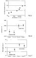
- FIG. 5 shows the dependence of the breakdown voltage of the discharge gap on the resistance of the partial coating according to the invention for a plurality of mercury-free metal halide high-pressure discharge lamps with a rated power of 35 watt, which are provided with a different thickness partial coating shown.
- the resistance of the coating in the unit ohms / cm is plotted on a logarithmic scale and on the vertical axis the breakdown voltage of the discharge path of the lamp in kilovolts. The resistance was measured between two points of the coating, which were arranged at a distance of 1 cm.
- the breakdown voltage for lamps of this type whose partial coating has a resistance per unit length of less than or equal to 10 5 ohm / cm, the discharge path has a significantly reduced breakdown voltage.
- the thickness of the partial according to the invention Coating is therefore chosen so that its resistance per unit length is in the order of magnitude of 10 3 ohms / cm to 10 5 ohms / cm. With a resistance per unit length below 10 3 ohm / cm, the layer thickness is so large that it can adversely affect the optical properties of the headlamp system due to light reflection.
- the layer thickness is selected such that its resistance per unit length is in the order of 10 4 ohms / cm.
- the breakdown voltage of the discharge gap has been reduced in this case from 20 kV in uncoated lamps to about 17.5 kV.
- the coating according to the invention therefore correspondingly reduces the required ignition voltage.
- the translucent, electrically conductive coating is advantageously applied to the outer surface of the discharge vessel, since it is not exposed to the chemical attack of the metal halides and the discharge plasma there.
- the abovementioned coating is arranged at least in the region of the discharge space and extends over a part of the circumference of the discharge space in order to ensure a good capacitive coupling of the coating to at least one electrode and preferably even to both electrodes by the planar expansion of the coating.
- the light-transmitting, electrically conductive partial coating is formed such that it extends as far as the at least one molybdenum foil and one of the two sides the molybdenum foil faces the coating.
- the molybdenum foil and the coating form a type of plate capacitor, wherein the material of the discharge vessel, preferably quartz glass, arranged therebetween forms the dielectric of this capacitor.
- the light-transmitting, electrically conductive coating is advantageously on one Restricted below the electrodes arranged surface region of the discharge vessel.
- the coating reflects a portion of the infrared radiation generated by the discharge back into the discharge space and thus provides for selective heating of the colder, lying below the electrodes areas of the discharge vessel in which collect the metal halides used for the light generation.
- the efficiency of the lamp can be increased without also heating the hot regions of the discharge vessel lying above the electrodes.
- the application of the coating only on the colder underside of the discharge vessel reduces the thermal load of the coating, so that correspondingly lower demands can be placed on the thermal resistance of the coating materials.
- the lamps according to the invention of groups 3 and 4 have a further advantage over the uncoated lamps of groups 1 and 2.
- the lamps according to the invention of groups 3 and 4 have a higher burning voltage than the uncoated lamps of the groups 1 and 2.
- a correspondingly lower lamp current is required in the lamps according to the invention during lamp operation to achieve the desired rated power of 35 watts. Accordingly, the operating devices can be dimensioned for lower currents.
- the high-pressure discharge lamp is designed as a single-ended high-pressure discharge lamp whose discharge vessel has a socket-sealed end and a socket-sealed end from each of which a lead-out led out for the electrodes, wherein led out of the sockelfemen end power supply with a connected to the socket recycled current return.
- the translucent, electrically conductive coating on the basis of the above explanations and because this lamp is operated in a horizontal position with current recirculation running below the electrodes, is arranged on a surface region of the discharge vessel facing the current return.
- the abovementioned coating is preferably limited to a surface region of the discharge vessel which is arranged between the current return and the connection axis of the electrodes and extends in the longitudinal direction of the lamp over at least part of the discharge space and a part of one of the two ends of the discharge vessel.
- the surface region of the discharge vessel facing the current return plays only a minor role in the use of the high-pressure discharge lamp in a vehicle headlight for generating the desired light distribution. Therefore, even a slight absorption of light caused by the coating is meaningless.
- the high-pressure discharge lamp according to the invention is advantageously provided with a light-permeable outer bulb which encloses at least the discharge space of the discharge vessel.
- the glass of the outer envelope is doped with ultraviolet radiation absorbing agents to absorb the UV radiation emitted by the gas discharge.
- the space between the outer bulb and the discharge vessel is advantageously provided with a gas filling having a cold filling pressure in the range of 5 kPa to 150 kPa.
- Cold filling pressure here means the filling pressure measured at a gas filling temperature of 22 degrees Celsius.
- the gas filling removes gaseous contaminants such as water vapor and carbon dioxide and combustion gases formed during the lamp vessel sealing, and reduces the temperature gradient along the discharge vessel.
- the abovementioned gas filling advantageously contains inert gases which do not undergo any chemical reaction with the material of the coating according to the invention on the discharge vessel.
- the gas filling therefore preferably contains nitrogen or at least one noble gas.
- the gas filling advantageously contains small amounts of oxygen in order to counteract a diffusion of oxygen from the coating, which is preferably in the form of a doped tin oxide layer or ITO layer, on the discharge vessel.
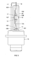
- the preferred exemplary embodiment of the invention shown schematically in FIG. 3 is a mercury-free metal halide high-pressure discharge lamp with an electrical power consumption of approximately 35 watts.
- This lamp is intended for use in a vehicle headlight. It has a two-sided sealed discharge vessel 30 made of quartz glass with a volume of 24 mm 3 , in which an ionizable filling, consisting of xenon and halides of the metals sodium, scandium, zinc and indium, gas-tight enclosed.
- the inner contour of the discharge vessel 10 is circular-cylindrical and its outer contour is ellipsoidal.
- the inner diameter of the discharge space 106 is 2.6 mm and its outer diameter is 6.3 mm.
- the two ends 101, 102 of the discharge vessel 10 are each sealed by means of a molybdenum foil sealing 103, 104.
- the electrodes 11, 12 are made of tungsten. Their thickness or their diameter is 0.30 mm. The distance between the electrodes 11, 12 is 4.2 mm.
- the electrodes 11, 12 are in each case electrically conductively connected to one of the molybdenum foil melts 103, 104 and via the base-remote power supply wire 13 and the current return 17 or via the socket-side power supply wire 14 to an electrical connection of the lamp base 15, which consists essentially of plastic.
- the discharge vessel 10 is enveloped by a glass outer bulb 16.
- the outer bulb 16 has an extension 161 anchored in the base 15.
- the discharge vessel 10 has a tubular extension 105 made of quartz glass on the base side, in which the socket-side power supply 14 extends:
- the surface region of the discharge vessel 10 facing the current return 17 is provided with a transparent, electrically conductive coating 107.
- This coating 107 extends in the longitudinal direction of the lamp over the entire length of the discharge space 106 and over a part, about 50 percent, of the length of the sealed ends 101, 102 of the discharge vessel 10.
- the coating 107 is mounted on the outside of the discharge vessel 10 and extends over about 5 percent to 10 percent of the circumference of the discharge vessel 10.
- FIGS. 1 and 2 show two different views of the discharge vessel 10 and the coating 107 of the high-pressure discharge lamp depicted in FIG.
- the coating 107 covers both ends 101, 102 of the discharge vessel 10 in a symmetrical manner.
- the coating 107 consists of doped tin oxide, for example of tin oxide doped with fluorine or antimony or, for example, boron and / or lithium-doped tin oxide.
- This high-pressure discharge lamp is operated in a horizontal position, that is, with arranged in a horizontal plane electrodes 11, 12, wherein the lamp is oriented such that the current return path 17 extends below the discharge vessel 30 and the outer bulb 16.
- the space between the outer bulb 16 and the discharge vessel 10 is filled with an inert gas having a cold filling pressure in the range of 5 kPa to 150 kPa.
- the inert gas is mixed with small amounts of oxygen.
- the amount of oxygen is adjusted so that, on the one hand, diffusion of oxygen from the tin oxide layer 107 is prevented and, on the other hand, no oxidation of the dopants in the tin oxide coating 107 is caused.
- the inert gas is preferably nitrogen or a noble gas or a noble gas mixture or a nitrogen-noble gas mixture.
- FIG. 4 shows the discharge vessel 10 of the high-pressure discharge lamp depicted in FIG. 3 with an alternative coating 107 '.
- the coating 107 ' differs from the above-described coating 107 only in that the coating 107' extends in the longitudinal direction of the lamp only over the length of the discharge space 106 and about 50 percent of the length of the socket-proximal end 101 of the discharge vessel 10.
- the coating 107 can also consist of another light-transmitting, electrically conductive material.
- it may be formed as a so-called ITO layer, that is, an indium tin oxide layer.
- the ITO layer may comprise, for example, 90 weight percent indium oxide and 10 weight percent tin oxide.
- the coating 107 or 107 ' can be electrically coupled, for example by suitable means, to an ignition device in order to apply to the high-pressure discharge lamp via the coating 107, 107' voltage pulses for igniting the gas discharge in the discharge space 106.
- the coating 107 or 107 ' may extend over the entire surface of the discharge vessel 10. But it is also possible that the coating 107 or 107 'extends in the region of the discharge space 106, for example, only over half or a third of the circumference of the discharge vessel 10. In the region of the ends 101, 102 of the discharge vessel 10, the coating 107 or 107 'may extend, for example, over the entire circumference of the discharge vessel 10 or even over a third, half or other fraction of the discharge vessel circumference.
- the coating 107 or 107 ' is preferably designed such that it serves as an ignition aid and for heating the coldest point of the discharge vessel, the so-called cold spot.
- the electrical resistance of the translucent coating 107 or 107 ' is in the range of 40,000 ohms to 200,000 ohms.
Landscapes
- Discharge Lamps And Accessories Thereof (AREA)
- Common Detailed Techniques For Electron Tubes Or Discharge Tubes (AREA)
Applications Claiming Priority (4)
| Application Number | Priority Date | Filing Date | Title |
|---|---|---|---|
| DE200410043636 DE102004043636A1 (de) | 2004-09-07 | 2004-09-07 | Hochdruckentladungslampe |
| DE200410050303 DE102004050303A1 (de) | 2004-10-14 | 2004-10-14 | Hochdruckentladungslampe |
| DE200410053011 DE102004053011A1 (de) | 2004-10-29 | 2004-10-29 | Hochdruckentladungslampe |
| DE200410057852 DE102004057852A1 (de) | 2004-11-30 | 2004-11-30 | Hochdruckentladungslampe |
Publications (2)
| Publication Number | Publication Date |
|---|---|
| EP1632985A1 true EP1632985A1 (fr) | 2006-03-08 |
| EP1632985B1 EP1632985B1 (fr) | 2014-06-25 |
Family
ID=35311524
Family Applications (1)
| Application Number | Title | Priority Date | Filing Date |
|---|---|---|---|
| EP05017122.2A Expired - Lifetime EP1632985B1 (fr) | 2004-09-07 | 2005-08-05 | Lampe à decharge haute pression |
Country Status (4)
| Country | Link |
|---|---|
| US (1) | US7705540B2 (fr) |
| EP (1) | EP1632985B1 (fr) |
| JP (1) | JP4956829B2 (fr) |
| KR (1) | KR101216458B1 (fr) |
Cited By (18)
| Publication number | Priority date | Publication date | Assignee | Title |
|---|---|---|---|---|
| WO2007101827A1 (fr) * | 2006-03-07 | 2007-09-13 | Patent-Treuhand-Gesellschaft für elektrische Glühlampen mbH | Procédé de fabrication d'une lampe à décharge et lampe fabriquée selon un tel procédé |
| WO2008007283A3 (fr) * | 2006-07-07 | 2008-05-15 | Philips Intellectual Property | Lampe à décharge de gaz |
| DE102007018614A1 (de) | 2007-04-19 | 2008-10-23 | Osram Gesellschaft mit beschränkter Haftung | Hochdruckentladungslampe und Fahrzeugscheinwerfer mit Hochdruckentladungslampe |
| DE102007043165A1 (de) | 2007-09-11 | 2009-03-12 | Osram Gesellschaft mit beschränkter Haftung | Hochdruckentladungslampe und Fahrzeugscheinwerfer mit Hochdruckentladungslampe |
| DE102008009144A1 (de) | 2008-02-14 | 2009-08-20 | Osram Gesellschaft mit beschränkter Haftung | Verfahren zum Zünden der Gasentladung in einer Hochdruckentladungslampe |
| DE102008014096A1 (de) | 2008-03-05 | 2009-09-10 | Osram Gesellschaft mit beschränkter Haftung | Wolframelektrode für Hochdruckentladungslampen und Hochdruckentladungslampe mit einer Wolframelektrode |
| DE102008026521A1 (de) | 2008-06-03 | 2009-12-10 | Osram Gesellschaft mit beschränkter Haftung | Thoriumfreie Hochdruckentladungslampe für Hochfrequenzbetrieb |
| DE102008057703A1 (de) | 2008-11-17 | 2010-05-20 | Osram Gesellschaft mit beschränkter Haftung | Quecksilberfreie Entladungslampe |
| DE102009052999A1 (de) | 2009-11-12 | 2011-05-19 | Osram Gesellschaft mit beschränkter Haftung | Hochdruckentladungslampe |
| DE202011103862U1 (de) | 2011-07-29 | 2011-10-24 | Osram Ag | Hochdruckentladungslampe |
| WO2011131559A1 (fr) | 2010-04-23 | 2011-10-27 | Osram Gesellschaft mit beschränkter Haftung | Lampe à décharge haute pression |
| DE102010062193A1 (de) | 2010-11-30 | 2012-05-31 | Osram Ag | Glasartikel |
| DE102010063755A1 (de) | 2010-12-10 | 2012-06-14 | Osram Ag | Hochdruckentladungslampe |
| DE102011003141A1 (de) | 2011-01-26 | 2012-07-26 | Osram Ag | Hochdruckentladungslampe |
| DE102013223708A1 (de) | 2013-11-20 | 2015-05-21 | Osram Gmbh | Hochdruckentladungslampe für Kraftfahrzeugscheinwerfer |
| DE102014204932A1 (de) | 2014-03-17 | 2015-09-17 | Osram Gmbh | Hochdruckentladungslampe |
| DE102015200162A1 (de) | 2015-01-08 | 2016-07-14 | Osram Gmbh | Hochdruckentladungslampe |
| DE102015211915A1 (de) | 2015-06-26 | 2016-12-29 | Osram Gmbh | Hochdruckentladungslampe für Kraftfahrzeugscheinwerfer |
Families Citing this family (8)
| Publication number | Priority date | Publication date | Assignee | Title |
|---|---|---|---|---|
| JP2007042369A (ja) * | 2005-08-02 | 2007-02-15 | Harison Toshiba Lighting Corp | メタルハライドランプおよび照明装置 |
| DE102006007218A1 (de) * | 2006-02-15 | 2007-08-16 | Patent-Treuhand-Gesellschaft für elektrische Glühlampen mbH | Hochdruckentladungslampe |
| EP2122662A1 (fr) * | 2007-03-12 | 2009-11-25 | Philips Intellectual Property & Standards GmbH | Lampe à décharge à faible énergie présentant une grande efficacité |
| JP2008293912A (ja) * | 2007-05-28 | 2008-12-04 | Phoenix Denki Kk | 高圧放電灯およびこれを用いた光源装置 |
| JP2010530606A (ja) * | 2007-06-21 | 2010-09-09 | コーニンクレッカ フィリップス エレクトロニクス エヌ ヴィ | スタータアンテナを有する高圧放電ランプ |
| JP5493694B2 (ja) * | 2009-06-25 | 2014-05-14 | 東芝ライテック株式会社 | 放電ランプ |
| DE102010028222A1 (de) * | 2010-04-27 | 2011-10-27 | Osram Gesellschaft mit beschränkter Haftung | Verfahren zum Betreiben einer Gasentladungslampe und Gasentladungslampensystem |
| TWI417474B (zh) * | 2010-05-31 | 2013-12-01 | 明志科技大學 | 可降低電磁輻射的燈泡與燈具 |
Citations (9)
| Publication number | Priority date | Publication date | Assignee | Title |
|---|---|---|---|---|
| DE717783C (de) * | 1939-08-31 | 1942-02-23 | Patra Patent Treuhand | Auf der Gefaessinnenwand angebrachter durchsichtiger und leitender Zuenderleichterungsbelag fuer elektrische Entladungslampen oder -roehren |
| GB1012574A (en) * | 1962-05-02 | 1965-12-08 | Philips Electronic Associated | Improvements in high-pressure mercury discharge lamps |
| US4701664A (en) * | 1986-01-09 | 1987-10-20 | Becton, Dickinson And Company | Mercury arc lamp suitable for inclusion in a flow cytometry apparatus |
| WO1991018413A1 (fr) * | 1990-05-22 | 1991-11-28 | Gte Products Corporation | Lampe a decharge en arc a faible perte de sodium |
| JPH0660851A (ja) | 1992-08-07 | 1994-03-04 | Matsushita Electric Ind Co Ltd | メタルハライドランプとその製造方法 |
| US20010041491A1 (en) * | 1997-12-16 | 2001-11-15 | Shouji Nishida | Flash discharge tube and method for producing the same |
| US6456005B1 (en) | 2000-10-31 | 2002-09-24 | General Electric Company | Materials and methods for application of conducting members on arc tubes |
| EP1369902A1 (fr) * | 2001-02-19 | 2003-12-10 | West Electric Co., Ltd. | Tube a decharge electrique, procede de fabrication dudit tube, dispositif stroboscopique utilisant ce tube et camera |
| EP0991107B1 (fr) | 1998-09-29 | 2004-01-28 | Patent-Treuhand-Gesellschaft für elektrische Glühlampen mbH | Dispositif d'éclairage muni d'une lampe à décharge |
Family Cites Families (11)
| Publication number | Priority date | Publication date | Assignee | Title |
|---|---|---|---|---|
| JPS5157979A (ja) * | 1974-11-15 | 1976-05-20 | Hitachi Ltd | Koatsukinzokujokihodento oyobi sonoseizohoho |
| US4918352A (en) * | 1988-11-07 | 1990-04-17 | General Electric Company | Metal halide lamps with oxidized frame parts |
| JPH065259A (ja) * | 1992-06-18 | 1994-01-14 | Hamamatsu Photonics Kk | 金属蒸気放電管 |
| US5844350A (en) * | 1992-12-18 | 1998-12-01 | General Electric Company | Coated arc tube for sodium vapor lamp |
| US5955846A (en) * | 1995-03-15 | 1999-09-21 | Matsushita Electric Industrial Co., Ltd. | Discharge lamp lighting device and a method for lighting a discharge lamp |
| US5610469A (en) * | 1995-03-16 | 1997-03-11 | General Electric Company | Electric lamp with ellipsoidal shroud |
| US5702179A (en) * | 1995-10-02 | 1997-12-30 | Osram Sylvania, Inc. | Discharge lamp having light-transmissive conductive coating for RF containment and heating |
| DE19610387A1 (de) * | 1996-03-16 | 1997-09-18 | Bosch Gmbh Robert | Gasentladungslampe, insbesondere für Kraftfahrzeug-Scheinwerfer |
| JP3224993B2 (ja) * | 1996-11-05 | 2001-11-05 | 松下電器産業株式会社 | 高圧放電ランプ及びその製造方法 |
| JP2000090879A (ja) * | 1998-09-14 | 2000-03-31 | Osuramu Melco Kk | メタルハライドランプ |
| KR100464709B1 (ko) * | 2001-03-12 | 2005-01-06 | 가부시키가이샤 고이토 세이사꾸쇼 | 방전 램프 장치 |
-
2005
- 2005-08-05 EP EP05017122.2A patent/EP1632985B1/fr not_active Expired - Lifetime
- 2005-08-25 US US11/210,878 patent/US7705540B2/en not_active Expired - Fee Related
- 2005-09-07 JP JP2005259422A patent/JP4956829B2/ja not_active Expired - Fee Related
- 2005-09-07 KR KR1020050083206A patent/KR101216458B1/ko not_active Expired - Fee Related
Patent Citations (9)
| Publication number | Priority date | Publication date | Assignee | Title |
|---|---|---|---|---|
| DE717783C (de) * | 1939-08-31 | 1942-02-23 | Patra Patent Treuhand | Auf der Gefaessinnenwand angebrachter durchsichtiger und leitender Zuenderleichterungsbelag fuer elektrische Entladungslampen oder -roehren |
| GB1012574A (en) * | 1962-05-02 | 1965-12-08 | Philips Electronic Associated | Improvements in high-pressure mercury discharge lamps |
| US4701664A (en) * | 1986-01-09 | 1987-10-20 | Becton, Dickinson And Company | Mercury arc lamp suitable for inclusion in a flow cytometry apparatus |
| WO1991018413A1 (fr) * | 1990-05-22 | 1991-11-28 | Gte Products Corporation | Lampe a decharge en arc a faible perte de sodium |
| JPH0660851A (ja) | 1992-08-07 | 1994-03-04 | Matsushita Electric Ind Co Ltd | メタルハライドランプとその製造方法 |
| US20010041491A1 (en) * | 1997-12-16 | 2001-11-15 | Shouji Nishida | Flash discharge tube and method for producing the same |
| EP0991107B1 (fr) | 1998-09-29 | 2004-01-28 | Patent-Treuhand-Gesellschaft für elektrische Glühlampen mbH | Dispositif d'éclairage muni d'une lampe à décharge |
| US6456005B1 (en) | 2000-10-31 | 2002-09-24 | General Electric Company | Materials and methods for application of conducting members on arc tubes |
| EP1369902A1 (fr) * | 2001-02-19 | 2003-12-10 | West Electric Co., Ltd. | Tube a decharge electrique, procede de fabrication dudit tube, dispositif stroboscopique utilisant ce tube et camera |
Cited By (27)
| Publication number | Priority date | Publication date | Assignee | Title |
|---|---|---|---|---|
| WO2007101827A1 (fr) * | 2006-03-07 | 2007-09-13 | Patent-Treuhand-Gesellschaft für elektrische Glühlampen mbH | Procédé de fabrication d'une lampe à décharge et lampe fabriquée selon un tel procédé |
| US7884549B2 (en) | 2006-07-07 | 2011-02-08 | Koninklijke Philips Electronics N.V. | Gas-discharge lamp |
| WO2008007283A3 (fr) * | 2006-07-07 | 2008-05-15 | Philips Intellectual Property | Lampe à décharge de gaz |
| DE102007018614A1 (de) | 2007-04-19 | 2008-10-23 | Osram Gesellschaft mit beschränkter Haftung | Hochdruckentladungslampe und Fahrzeugscheinwerfer mit Hochdruckentladungslampe |
| US8310156B2 (en) | 2007-04-19 | 2012-11-13 | Osram Ag | High-pressure discharge lamp and vehicle headlight with high-pressure discharge lamp |
| DE102007043165A1 (de) | 2007-09-11 | 2009-03-12 | Osram Gesellschaft mit beschränkter Haftung | Hochdruckentladungslampe und Fahrzeugscheinwerfer mit Hochdruckentladungslampe |
| DE102008009144A1 (de) | 2008-02-14 | 2009-08-20 | Osram Gesellschaft mit beschränkter Haftung | Verfahren zum Zünden der Gasentladung in einer Hochdruckentladungslampe |
| DE102008014096A1 (de) | 2008-03-05 | 2009-09-10 | Osram Gesellschaft mit beschränkter Haftung | Wolframelektrode für Hochdruckentladungslampen und Hochdruckentladungslampe mit einer Wolframelektrode |
| DE102008026521A1 (de) | 2008-06-03 | 2009-12-10 | Osram Gesellschaft mit beschränkter Haftung | Thoriumfreie Hochdruckentladungslampe für Hochfrequenzbetrieb |
| US8736165B2 (en) | 2008-11-17 | 2014-05-27 | Osram Gesellschaft Mit Beschraenkter Haftung | Mercury-free discharge lamp having a translucent discharge vessel |
| DE102008057703A1 (de) | 2008-11-17 | 2010-05-20 | Osram Gesellschaft mit beschränkter Haftung | Quecksilberfreie Entladungslampe |
| DE102009052999A1 (de) | 2009-11-12 | 2011-05-19 | Osram Gesellschaft mit beschränkter Haftung | Hochdruckentladungslampe |
| WO2011057903A1 (fr) | 2009-11-12 | 2011-05-19 | Osram Gesellschaft mit beschränkter Haftung | Lampe à décharge haute pression sans mercure et à teneur réduite en halogénures de zinc |
| WO2011131559A1 (fr) | 2010-04-23 | 2011-10-27 | Osram Gesellschaft mit beschränkter Haftung | Lampe à décharge haute pression |
| DE102010028156A1 (de) | 2010-04-23 | 2011-10-27 | Osram Gesellschaft mit beschränkter Haftung | Hochdruckentladungslampe |
| DE102010062193A1 (de) | 2010-11-30 | 2012-05-31 | Osram Ag | Glasartikel |
| WO2012072398A1 (fr) | 2010-11-30 | 2012-06-07 | Osram Ag | Article en verre pour la fabrication de lampes |
| WO2012076298A1 (fr) | 2010-12-10 | 2012-06-14 | Osram Ag | Lampe à décharge haute pression |
| DE102010063755A1 (de) | 2010-12-10 | 2012-06-14 | Osram Ag | Hochdruckentladungslampe |
| DE102011003141A1 (de) | 2011-01-26 | 2012-07-26 | Osram Ag | Hochdruckentladungslampe |
| WO2012101053A1 (fr) | 2011-01-26 | 2012-08-02 | Osram Ag | Lampe à décharge à haute pression |
| WO2013017325A1 (fr) | 2011-07-29 | 2013-02-07 | Osram Ag | Lampe à décharge à haute intensité dotée d'un auxiliaire d'allumage et dispositif de fonctionnement |
| DE202011103862U1 (de) | 2011-07-29 | 2011-10-24 | Osram Ag | Hochdruckentladungslampe |
| DE102013223708A1 (de) | 2013-11-20 | 2015-05-21 | Osram Gmbh | Hochdruckentladungslampe für Kraftfahrzeugscheinwerfer |
| DE102014204932A1 (de) | 2014-03-17 | 2015-09-17 | Osram Gmbh | Hochdruckentladungslampe |
| DE102015200162A1 (de) | 2015-01-08 | 2016-07-14 | Osram Gmbh | Hochdruckentladungslampe |
| DE102015211915A1 (de) | 2015-06-26 | 2016-12-29 | Osram Gmbh | Hochdruckentladungslampe für Kraftfahrzeugscheinwerfer |
Also Published As
| Publication number | Publication date |
|---|---|
| US20060049764A1 (en) | 2006-03-09 |
| KR20060051078A (ko) | 2006-05-19 |
| KR101216458B1 (ko) | 2012-12-28 |
| US7705540B2 (en) | 2010-04-27 |
| EP1632985B1 (fr) | 2014-06-25 |
| JP2006080078A (ja) | 2006-03-23 |
| JP4956829B2 (ja) | 2012-06-20 |
Similar Documents
| Publication | Publication Date | Title |
|---|---|---|
| EP1632985B1 (fr) | Lampe à decharge haute pression | |
| EP1984936B1 (fr) | Lampe à décharge à haute pression | |
| DE10354868B4 (de) | Quecksilber-freie Bogenentladungsröhre für eine Entladungslampeneinheit | |
| EP2499657B1 (fr) | Lampe à décharge haute pression sans mercure et à teneur réduite en halogénures de zinc | |
| EP2147456B1 (fr) | Lampe à décharge haute pression et phare de véhicule automobile avec lampe à décharge haute pression | |
| DE10204691C1 (de) | Quecksilberfreie Hochdruckgasentladungslampe und Beleuchtungseinheit mit einer solchen Hochdruckgasentladungslampe | |
| EP2347430B1 (fr) | Lampe à décharge sans mercure | |
| EP1754245A2 (fr) | Lampe a decharge haute pression | |
| DE102004043636A1 (de) | Hochdruckentladungslampe | |
| EP2529391B1 (fr) | Lampe à décharge haute pression | |
| DE102004057852A1 (de) | Hochdruckentladungslampe | |
| DE102004050303A1 (de) | Hochdruckentladungslampe | |
| DE102004053011A1 (de) | Hochdruckentladungslampe | |
| EP2499651A1 (fr) | Lampe à décharge à haute pression avec douille unilatérale | |
| EP3031071B1 (fr) | Lampe à décharge à haute pression pour phare de véhicule | |
| EP3072146B1 (fr) | Lampe à décharge à haute pression pour phare de véhicule automobile | |
| DE3321479A1 (de) | Hochdruckentladungslampe | |
| WO2009109566A1 (fr) | Électrode en tungstène pour lampes à décharge haute pression et lampe à décharge haute pression comportant une électrode en tungstène | |
| WO2009147041A2 (fr) | Lampe à décharge à haute pression sans thorium pour un mode de fonctionnement haute fréquence | |
| DE102007043165A1 (de) | Hochdruckentladungslampe und Fahrzeugscheinwerfer mit Hochdruckentladungslampe | |
| WO2008116493A1 (fr) | Lampe à incandescence à filament spiralé présentant une extrémité enveloppée | |
| WO2007101827A1 (fr) | Procédé de fabrication d'une lampe à décharge et lampe fabriquée selon un tel procédé | |
| DE19808365A1 (de) | Metallhalogenlampe | |
| DE102015200162A1 (de) | Hochdruckentladungslampe | |
| WO2014032925A1 (fr) | Lampe à décharge à haute pression avec des électrodes dotées d'un émetteur d'électrons |
Legal Events
| Date | Code | Title | Description |
|---|---|---|---|
| PUAI | Public reference made under article 153(3) epc to a published international application that has entered the european phase |
Free format text: ORIGINAL CODE: 0009012 |
|
| AK | Designated contracting states |
Kind code of ref document: A1 Designated state(s): AT BE BG CH CY CZ DE DK EE ES FI FR GB GR HU IE IS IT LI LT LU LV MC NL PL PT RO SE SI SK TR |
|
| AX | Request for extension of the european patent |
Extension state: AL BA HR MK YU |
|
| 17P | Request for examination filed |
Effective date: 20060821 |
|
| 17Q | First examination report despatched |
Effective date: 20060925 |
|
| AKX | Designation fees paid |
Designated state(s): AT BE BG CH CY CZ DE DK EE ES FI FR GB GR HU IE IS IT LI LT LU LV MC NL PL PT RO SE SI SK TR |
|
| RAP1 | Party data changed (applicant data changed or rights of an application transferred) |
Owner name: OSRAM GESELLSCHAFT MIT BESCHRAENKTER HAFTUNG |
|
| RAP1 | Party data changed (applicant data changed or rights of an application transferred) |
Owner name: OSRAM AG |
|
| RAP1 | Party data changed (applicant data changed or rights of an application transferred) |
Owner name: OSRAM GMBH |
|
| RAP1 | Party data changed (applicant data changed or rights of an application transferred) |
Owner name: OSRAM GMBH |
|
| GRAP | Despatch of communication of intention to grant a patent |
Free format text: ORIGINAL CODE: EPIDOSNIGR1 |
|
| INTG | Intention to grant announced |
Effective date: 20140219 |
|
| RIN1 | Information on inventor provided before grant (corrected) |
Inventor name: BOENIGK, MICHAEL Inventor name: GRUNDMANN, DIRK Inventor name: BEDYNEK, FLORIAN Inventor name: SCHIMKE, CONRAD Inventor name: REINERS, THOMAS DR. |
|
| RIN1 | Information on inventor provided before grant (corrected) |
Inventor name: BEDYNEK, FLORIAN Inventor name: SCHIMKE, CONRAD Inventor name: GRUNDMANN, DIRK Inventor name: REINERS, THOMAS DR. Inventor name: BOENIGK, MICHAEL |
|
| GRAS | Grant fee paid |
Free format text: ORIGINAL CODE: EPIDOSNIGR3 |
|
| GRAA | (expected) grant |
Free format text: ORIGINAL CODE: 0009210 |
|
| AK | Designated contracting states |
Kind code of ref document: B1 Designated state(s): AT BE BG CH CY CZ DE DK EE ES FI FR GB GR HU IE IS IT LI LT LU LV MC NL PL PT RO SE SI SK TR |
|
| REG | Reference to a national code |
Ref country code: GB Ref legal event code: FG4D Free format text: NOT ENGLISH |
|
| REG | Reference to a national code |
Ref country code: CH Ref legal event code: EP |
|
| REG | Reference to a national code |
Ref country code: AT Ref legal event code: REF Ref document number: 675142 Country of ref document: AT Kind code of ref document: T Effective date: 20140715 |
|
| REG | Reference to a national code |
Ref country code: IE Ref legal event code: FG4D Free format text: LANGUAGE OF EP DOCUMENT: GERMAN |
|
| REG | Reference to a national code |
Ref country code: DE Ref legal event code: R096 Ref document number: 502005014407 Country of ref document: DE Effective date: 20140807 |
|
| PG25 | Lapsed in a contracting state [announced via postgrant information from national office to epo] |
Ref country code: LT Free format text: LAPSE BECAUSE OF FAILURE TO SUBMIT A TRANSLATION OF THE DESCRIPTION OR TO PAY THE FEE WITHIN THE PRESCRIBED TIME-LIMIT Effective date: 20140625 Ref country code: FI Free format text: LAPSE BECAUSE OF FAILURE TO SUBMIT A TRANSLATION OF THE DESCRIPTION OR TO PAY THE FEE WITHIN THE PRESCRIBED TIME-LIMIT Effective date: 20140625 Ref country code: GR Free format text: LAPSE BECAUSE OF FAILURE TO SUBMIT A TRANSLATION OF THE DESCRIPTION OR TO PAY THE FEE WITHIN THE PRESCRIBED TIME-LIMIT Effective date: 20140926 Ref country code: CY Free format text: LAPSE BECAUSE OF FAILURE TO SUBMIT A TRANSLATION OF THE DESCRIPTION OR TO PAY THE FEE WITHIN THE PRESCRIBED TIME-LIMIT Effective date: 20140625 |
|
| REG | Reference to a national code |
Ref country code: NL Ref legal event code: VDEP Effective date: 20140625 |
|
| REG | Reference to a national code |
Ref country code: LT Ref legal event code: MG4D |
|
| PG25 | Lapsed in a contracting state [announced via postgrant information from national office to epo] |
Ref country code: LV Free format text: LAPSE BECAUSE OF FAILURE TO SUBMIT A TRANSLATION OF THE DESCRIPTION OR TO PAY THE FEE WITHIN THE PRESCRIBED TIME-LIMIT Effective date: 20140625 Ref country code: SE Free format text: LAPSE BECAUSE OF FAILURE TO SUBMIT A TRANSLATION OF THE DESCRIPTION OR TO PAY THE FEE WITHIN THE PRESCRIBED TIME-LIMIT Effective date: 20140625 |
|
| PG25 | Lapsed in a contracting state [announced via postgrant information from national office to epo] |
Ref country code: CZ Free format text: LAPSE BECAUSE OF FAILURE TO SUBMIT A TRANSLATION OF THE DESCRIPTION OR TO PAY THE FEE WITHIN THE PRESCRIBED TIME-LIMIT Effective date: 20140625 Ref country code: SK Free format text: LAPSE BECAUSE OF FAILURE TO SUBMIT A TRANSLATION OF THE DESCRIPTION OR TO PAY THE FEE WITHIN THE PRESCRIBED TIME-LIMIT Effective date: 20140625 Ref country code: RO Free format text: LAPSE BECAUSE OF FAILURE TO SUBMIT A TRANSLATION OF THE DESCRIPTION OR TO PAY THE FEE WITHIN THE PRESCRIBED TIME-LIMIT Effective date: 20140625 Ref country code: PT Free format text: LAPSE BECAUSE OF FAILURE TO SUBMIT A TRANSLATION OF THE DESCRIPTION OR TO PAY THE FEE WITHIN THE PRESCRIBED TIME-LIMIT Effective date: 20141027 Ref country code: ES Free format text: LAPSE BECAUSE OF FAILURE TO SUBMIT A TRANSLATION OF THE DESCRIPTION OR TO PAY THE FEE WITHIN THE PRESCRIBED TIME-LIMIT Effective date: 20140625 Ref country code: EE Free format text: LAPSE BECAUSE OF FAILURE TO SUBMIT A TRANSLATION OF THE DESCRIPTION OR TO PAY THE FEE WITHIN THE PRESCRIBED TIME-LIMIT Effective date: 20140625 |
|
| PG25 | Lapsed in a contracting state [announced via postgrant information from national office to epo] |
Ref country code: PL Free format text: LAPSE BECAUSE OF FAILURE TO SUBMIT A TRANSLATION OF THE DESCRIPTION OR TO PAY THE FEE WITHIN THE PRESCRIBED TIME-LIMIT Effective date: 20140625 Ref country code: NL Free format text: LAPSE BECAUSE OF FAILURE TO SUBMIT A TRANSLATION OF THE DESCRIPTION OR TO PAY THE FEE WITHIN THE PRESCRIBED TIME-LIMIT Effective date: 20140625 Ref country code: IS Free format text: LAPSE BECAUSE OF FAILURE TO SUBMIT A TRANSLATION OF THE DESCRIPTION OR TO PAY THE FEE WITHIN THE PRESCRIBED TIME-LIMIT Effective date: 20141025 |
|
| REG | Reference to a national code |
Ref country code: DE Ref legal event code: R097 Ref document number: 502005014407 Country of ref document: DE |
|
| PG25 | Lapsed in a contracting state [announced via postgrant information from national office to epo] |
Ref country code: MC Free format text: LAPSE BECAUSE OF FAILURE TO SUBMIT A TRANSLATION OF THE DESCRIPTION OR TO PAY THE FEE WITHIN THE PRESCRIBED TIME-LIMIT Effective date: 20140625 Ref country code: LU Free format text: LAPSE BECAUSE OF FAILURE TO SUBMIT A TRANSLATION OF THE DESCRIPTION OR TO PAY THE FEE WITHIN THE PRESCRIBED TIME-LIMIT Effective date: 20140805 |
|
| REG | Reference to a national code |
Ref country code: CH Ref legal event code: PL |
|
| PG25 | Lapsed in a contracting state [announced via postgrant information from national office to epo] |
Ref country code: LI Free format text: LAPSE BECAUSE OF NON-PAYMENT OF DUE FEES Effective date: 20140831 Ref country code: CH Free format text: LAPSE BECAUSE OF NON-PAYMENT OF DUE FEES Effective date: 20140831 Ref country code: IT Free format text: LAPSE BECAUSE OF FAILURE TO SUBMIT A TRANSLATION OF THE DESCRIPTION OR TO PAY THE FEE WITHIN THE PRESCRIBED TIME-LIMIT Effective date: 20140625 Ref country code: DK Free format text: LAPSE BECAUSE OF FAILURE TO SUBMIT A TRANSLATION OF THE DESCRIPTION OR TO PAY THE FEE WITHIN THE PRESCRIBED TIME-LIMIT Effective date: 20140625 Ref country code: BE Free format text: LAPSE BECAUSE OF NON-PAYMENT OF DUE FEES Effective date: 20140831 |
|
| PLBE | No opposition filed within time limit |
Free format text: ORIGINAL CODE: 0009261 |
|
| STAA | Information on the status of an ep patent application or granted ep patent |
Free format text: STATUS: NO OPPOSITION FILED WITHIN TIME LIMIT |
|
| REG | Reference to a national code |
Ref country code: IE Ref legal event code: MM4A |
|
| GBPC | Gb: european patent ceased through non-payment of renewal fee |
Effective date: 20140925 |
|
| 26N | No opposition filed |
Effective date: 20150326 |
|
| PG25 | Lapsed in a contracting state [announced via postgrant information from national office to epo] |
Ref country code: GB Free format text: LAPSE BECAUSE OF NON-PAYMENT OF DUE FEES Effective date: 20140925 |
|
| PG25 | Lapsed in a contracting state [announced via postgrant information from national office to epo] |
Ref country code: IE Free format text: LAPSE BECAUSE OF NON-PAYMENT OF DUE FEES Effective date: 20140805 |
|
| REG | Reference to a national code |
Ref country code: AT Ref legal event code: MM01 Ref document number: 675142 Country of ref document: AT Kind code of ref document: T Effective date: 20140805 |
|
| PG25 | Lapsed in a contracting state [announced via postgrant information from national office to epo] |
Ref country code: AT Free format text: LAPSE BECAUSE OF NON-PAYMENT OF DUE FEES Effective date: 20140805 Ref country code: SI Free format text: LAPSE BECAUSE OF FAILURE TO SUBMIT A TRANSLATION OF THE DESCRIPTION OR TO PAY THE FEE WITHIN THE PRESCRIBED TIME-LIMIT Effective date: 20140625 |
|
| PG25 | Lapsed in a contracting state [announced via postgrant information from national office to epo] |
Ref country code: BG Free format text: LAPSE BECAUSE OF FAILURE TO SUBMIT A TRANSLATION OF THE DESCRIPTION OR TO PAY THE FEE WITHIN THE PRESCRIBED TIME-LIMIT Effective date: 20140625 |
|
| PG25 | Lapsed in a contracting state [announced via postgrant information from national office to epo] |
Ref country code: TR Free format text: LAPSE BECAUSE OF FAILURE TO SUBMIT A TRANSLATION OF THE DESCRIPTION OR TO PAY THE FEE WITHIN THE PRESCRIBED TIME-LIMIT Effective date: 20140625 Ref country code: HU Free format text: LAPSE BECAUSE OF FAILURE TO SUBMIT A TRANSLATION OF THE DESCRIPTION OR TO PAY THE FEE WITHIN THE PRESCRIBED TIME-LIMIT; INVALID AB INITIO Effective date: 20050805 |
|
| REG | Reference to a national code |
Ref country code: FR Ref legal event code: PLFP Year of fee payment: 12 |
|
| REG | Reference to a national code |
Ref country code: FR Ref legal event code: PLFP Year of fee payment: 13 |
|
| REG | Reference to a national code |
Ref country code: FR Ref legal event code: PLFP Year of fee payment: 14 |
|
| PGFP | Annual fee paid to national office [announced via postgrant information from national office to epo] |
Ref country code: FR Payment date: 20180827 Year of fee payment: 14 |
|
| PGFP | Annual fee paid to national office [announced via postgrant information from national office to epo] |
Ref country code: DE Payment date: 20190822 Year of fee payment: 15 |
|
| PG25 | Lapsed in a contracting state [announced via postgrant information from national office to epo] |
Ref country code: FR Free format text: LAPSE BECAUSE OF NON-PAYMENT OF DUE FEES Effective date: 20190831 |
|
| REG | Reference to a national code |
Ref country code: DE Ref legal event code: R119 Ref document number: 502005014407 Country of ref document: DE |
|
| PG25 | Lapsed in a contracting state [announced via postgrant information from national office to epo] |
Ref country code: DE Free format text: LAPSE BECAUSE OF NON-PAYMENT OF DUE FEES Effective date: 20210302 |