EP1633034A2 - Moteur vibrant et terminal portable avec un tel moteur - Google Patents
Moteur vibrant et terminal portable avec un tel moteur Download PDFInfo
- Publication number
- EP1633034A2 EP1633034A2 EP05018179A EP05018179A EP1633034A2 EP 1633034 A2 EP1633034 A2 EP 1633034A2 EP 05018179 A EP05018179 A EP 05018179A EP 05018179 A EP05018179 A EP 05018179A EP 1633034 A2 EP1633034 A2 EP 1633034A2
- Authority
- EP
- European Patent Office
- Prior art keywords
- magnet
- pole
- stator yoke
- rotor
- vibrating motor
- Prior art date
- Legal status (The legal status is an assumption and is not a legal conclusion. Google has not performed a legal analysis and makes no representation as to the accuracy of the status listed.)
- Withdrawn
Links
- 230000005415 magnetization Effects 0.000 claims description 34
- 230000004907 flux Effects 0.000 claims description 15
- 239000000696 magnetic material Substances 0.000 claims description 10
- 238000004804 winding Methods 0.000 claims description 9
- 230000001133 acceleration Effects 0.000 description 9
- 230000001413 cellular effect Effects 0.000 description 7
- 230000005405 multipole Effects 0.000 description 5
- 230000001788 irregular Effects 0.000 description 4
- 229910052751 metal Inorganic materials 0.000 description 4
- 239000002184 metal Substances 0.000 description 4
- 230000009467 reduction Effects 0.000 description 4
- 238000010276 construction Methods 0.000 description 3
- 230000000694 effects Effects 0.000 description 3
- 239000011248 coating agent Substances 0.000 description 2
- 238000000576 coating method Methods 0.000 description 2
- 238000001514 detection method Methods 0.000 description 2
- 238000010586 diagram Methods 0.000 description 2
- 238000005516 engineering process Methods 0.000 description 2
- 230000006870 function Effects 0.000 description 2
- 230000005484 gravity Effects 0.000 description 2
- 230000006872 improvement Effects 0.000 description 2
- 238000012423 maintenance Methods 0.000 description 2
- 230000007246 mechanism Effects 0.000 description 2
- 239000007769 metal material Substances 0.000 description 2
- 239000004065 semiconductor Substances 0.000 description 2
- 229910052779 Neodymium Inorganic materials 0.000 description 1
- 229910001080 W alloy Inorganic materials 0.000 description 1
- 230000009471 action Effects 0.000 description 1
- 229910045601 alloy Inorganic materials 0.000 description 1
- 239000000956 alloy Substances 0.000 description 1
- 238000005452 bending Methods 0.000 description 1
- 239000011230 binding agent Substances 0.000 description 1
- 150000001875 compounds Chemical class 0.000 description 1
- 230000008878 coupling Effects 0.000 description 1
- 238000010168 coupling process Methods 0.000 description 1
- 238000005859 coupling reaction Methods 0.000 description 1
- 239000006247 magnetic powder Substances 0.000 description 1
- 238000000034 method Methods 0.000 description 1
- 239000000203 mixture Substances 0.000 description 1
- QEFYFXOXNSNQGX-UHFFFAOYSA-N neodymium atom Chemical compound [Nd] QEFYFXOXNSNQGX-UHFFFAOYSA-N 0.000 description 1
- 229910001172 neodymium magnet Inorganic materials 0.000 description 1
- 210000000056 organ Anatomy 0.000 description 1
- 230000008569 process Effects 0.000 description 1
- 239000011347 resin Substances 0.000 description 1
- 229920005989 resin Polymers 0.000 description 1
- 230000002441 reversible effect Effects 0.000 description 1
- 230000035807 sensation Effects 0.000 description 1
- 238000005476 soldering Methods 0.000 description 1
- 230000008961 swelling Effects 0.000 description 1
- 230000001360 synchronised effect Effects 0.000 description 1
- 238000003466 welding Methods 0.000 description 1
Images




Classifications
-
- H—ELECTRICITY
- H02—GENERATION; CONVERSION OR DISTRIBUTION OF ELECTRIC POWER
- H02K—DYNAMO-ELECTRIC MACHINES
- H02K7/00—Arrangements for handling mechanical energy structurally associated with dynamo-electric machines, e.g. structural association with mechanical driving motors or auxiliary dynamo-electric machines
- H02K7/06—Means for converting reciprocating motion into rotary motion or vice versa
- H02K7/061—Means for converting reciprocating motion into rotary motion or vice versa using rotary unbalanced masses
- H02K7/063—Means for converting reciprocating motion into rotary motion or vice versa using rotary unbalanced masses integrally combined with motor parts, e.g. motors with eccentric rotors
-
- B—PERFORMING OPERATIONS; TRANSPORTING
- B06—GENERATING OR TRANSMITTING MECHANICAL VIBRATIONS IN GENERAL
- B06B—METHODS OR APPARATUS FOR GENERATING OR TRANSMITTING MECHANICAL VIBRATIONS OF INFRASONIC, SONIC, OR ULTRASONIC FREQUENCY, e.g. FOR PERFORMING MECHANICAL WORK IN GENERAL
- B06B1/00—Methods or apparatus for generating mechanical vibrations of infrasonic, sonic, or ultrasonic frequency
- B06B1/02—Methods or apparatus for generating mechanical vibrations of infrasonic, sonic, or ultrasonic frequency making use of electrical energy
- B06B1/04—Methods or apparatus for generating mechanical vibrations of infrasonic, sonic, or ultrasonic frequency making use of electrical energy operating with electromagnetism
- B06B1/045—Methods or apparatus for generating mechanical vibrations of infrasonic, sonic, or ultrasonic frequency making use of electrical energy operating with electromagnetism using vibrating magnet, armature or coil system
-
- H—ELECTRICITY
- H02—GENERATION; CONVERSION OR DISTRIBUTION OF ELECTRIC POWER
- H02K—DYNAMO-ELECTRIC MACHINES
- H02K1/00—Details of the magnetic circuit
- H02K1/06—Details of the magnetic circuit characterised by the shape, form or construction
- H02K1/22—Rotating parts of the magnetic circuit
- H02K1/27—Rotor cores with permanent magnets
-
- H—ELECTRICITY
- H02—GENERATION; CONVERSION OR DISTRIBUTION OF ELECTRIC POWER
- H02K—DYNAMO-ELECTRIC MACHINES
- H02K15/00—Processes or apparatus specially adapted for manufacturing, assembling, maintaining or repairing of dynamo-electric machines
- H02K15/02—Processes or apparatus specially adapted for manufacturing, assembling, maintaining or repairing of dynamo-electric machines of stator or rotor bodies
- H02K15/03—Processes or apparatus specially adapted for manufacturing, assembling, maintaining or repairing of dynamo-electric machines of stator or rotor bodies having permanent magnets
-
- H—ELECTRICITY
- H04—ELECTRIC COMMUNICATION TECHNIQUE
- H04M—TELEPHONIC COMMUNICATION
- H04M19/00—Current supply arrangements for telephone systems
- H04M19/02—Current supply arrangements for telephone systems providing ringing current or supervisory tones, e.g. dialling tone or busy tone
- H04M19/04—Current supply arrangements for telephone systems providing ringing current or supervisory tones, e.g. dialling tone or busy tone the ringing-current being generated at the substations
- H04M19/047—Vibrating means for incoming calls
Definitions
- the present invention relates to a vibrating motor including a vibration mechanism used for vibration generation of, for example, a cellular phone and a portable terminal apparatus using the same.
- a DC (direct current) motor with brush was used for vibration generation of an initial cellular phone. Since semiconductor integrated technology in those days was less advanced, it was difficult to specially produce a circuit including also a control circuit of a motor in the narrow cellular phone, and the DC motor with brush was used mainly since its cost was low and trouble seldom occurred.
- the DC motor with brush is classified into various types according to use place or use. In a cylinder type which is incorporated in a watch or the like, since the rotation surface of a shaft is in the thickness direction of the watch, the reduction in thickness is difficult, and it is difficult to provide an external eccentric weight in order to obtain a vibration amount. In a coin type, the reduction in thickness can be achieved, however, its lifetime is short, a start time and a stop time become long, and its control becomes difficult.
- the semiconductor integrated technology has been advanced, and it has been able to afford to incorporate a control circuit of a brushless motor or the like, and therefore, the control circuit of the brushless motor can be incorporated for vibration generation.
- the brushless motor Since the brushless motor has no brush, its lifetime is very long (high reliability), the vibration amount can be adjusted by rotation speed control using frequency, and the structure becomes simple.
- JP-A-9-252573 discloses a vibrating motor on the assumption that it is incorporated in a watch case.
- Figs. 6A-6C are structural views of one type of vibrating motor, which is disclosed in JP-A-9-252573.
- Fig. 6A is a view showing a magnetic circuit of the vibrating motor disclosed in JP-A-9-252573
- Fig. 6B is a characteristic explanation view of the vibrating motor
- Fig. 6C is an external appearance view of the vibrating motor.
- the magnetic circuit of a stepping motor of Fig. 6A includes a rotor 109 made of a bipolar permanent magnet 108, a coil 112 including an exciting coil and a detection coil for detecting the rotation position of the rotor, and a bipolar stator 111 including a flat part 140 magnetically coupled with the rotor 109 through a gap 110 and having a rotor hole 141 for housing and disposing the rotor 109, two connection parts 122 and 123 formed by bending at substantially right angles with respect to the flat part 140, and connection end parts 124 and 125 bent to be connected to core end parts 126 of the coil 112. Wide surfaces of the connection end parts 124 and 125 and wide surfaces of the core end parts 126 are connected with each other at the same surface. In order to avoid a magnetic short circuiting between the stator 111 and the coil 112, a wide surface 113 of the connection part 123 is opposite to a narrow surface of the core of the coil 112.
- a rotor shaft 102 of the rotor 109 is received by two rotor bearings 115 and 116, and the rotor shaft 102 and the coil 112 are disposed in a cylindrical shaft direction.
- a circuit board 118 which includes a driver IC 117 of the stepping motor, two power terminals 103 and 104 and a control terminal 105 and is disposed so that its longitudinal direction becomes the direction of a cylindrical shaft, the stator 111 and the coil 112 are fixed by screws 119 and 120 to a frame 106 through screw holes 107 provided in the frame 106 (Fig. 6C).
- a coil terminal of the coil 112 is adhered and conducted to each coil connection pattern (not shown) of the circuit board 118.
- the stepping motor can adopt the cylindrical shape structure including the rotor 109 made of the bipolar permanent magnet 108, the bipolar stator 111, the coil 112, and the circuit board 118. That is, according to the above structure, the arrangement can be made so that the direction of magnetic field generated by the coil 112 intersects with the rotation plane of the rotor 109.
- Fig. 6C is an external appearance view of the stepping motor with an eccentric weight.
- the stepping motor with the eccentric weight is such that an eccentric weight 128 is fixed to one end side of the rotor shaft 102 of the stepping motor so that the vibration surface of the eccentric weight 128 becomes perpendicular to the rotor shaft 102.
- An object of an illustrative, non-limiting embodiment of the invention is to overcome the disadvantage described above, and to provide a vibrating motor including a stepping motor in which control is simple, large vibration is generated, and drive torque can be efficiently generated, and to provide a portable terminal apparatus using the same. Also, the invention is not required to overcome the disadvantage described above, and an illustrative, non-limiting embodiment of the invention may overcome different disadvantages or may not overcome any disadvantages.
- An illustrative, non-limiting embodiment of a vibrating motor of the invention is characterized in that a single-phase annular stator coil is surrounded by a stator yoke having pole teeth, an arc-shaped magnet is rotatably disposed along the stator yoke so as to be opposite to the pole teeth, and an arc-shaped eccentric weight is rotatably disposed outside the stator yoke in a radial direction.
- An illustrative, non-limiting embodiment of a portable terminal apparatus of the invention uses, as a vibrating motor used therefor, the vibrating motor basically having the above structure.
- control is simple, large vibration is generated, and drive torque can be efficiently generated.
- the structure is simple and the control circuit can be simply constructed.
- the rotation speed can be controlled to be constant.
- the vibration can be greatly changed.
- the single-phase stepping motor is pulse driven, the rotation of the vibrating motor can be stopped. Accordingly, the vibration can be stopped in a short stop time.
- stator yoke having the pole teeth is provided to surround the single-phase annular stator coil, and the rotor and the like are rotatably provided along the stator yoke, reduction in thickness and high speed driving become possible.
- the eccentric weight is disposed outside the annular stator yoke in the radial direction, the radius from the center can be made large, and strong vibration can be generated.
- the width of the magnetic pole that is, an arc length in the embodiments becomes short (as compared with one magnetized in the circumferential direction)
- plural magnets can be closely disposed in the circumferential direction, and magnetization at a fine pitch becomes easy.
- a step width can be made narrow, and accordingly, the outer diameter of the vibrating motor can be made small.
- the magnet including the rotor magnet and the commutating-pole magnet is magnetized in the radial direction, the adjustment of the stop position becomes easy.
- the magnet is magnetized in the radial direction
- plural magnets are closely disposed in the circumferential direction.
- the magnetic pole arrangement at a fine pitch becomes easy.
- an odd number of poles can be arranged, and the space is effectively used, and an efficient motor design becomes possible.
- stator coil is formed by winding and fusion-bonding the self-bonding wire, imbalance between the wound windings is suppressed, and the uniformity of arrangement can be realized. Besides, since a shift in the windings due to vibration or the like does not occur, the characteristics become stable.
- the rotation space can be shared, and the shape of the vibrating motor can be made small.
- the eccentric weight contains the magnetic material, and the irregularities having a pitch substantially equal to the pole teeth of the stator yoke are provided on the surface opposite to the stator yoke, the drive force of the vibrating motor can be increased.
- a flat cylindrical shape can be formed, while high speed rotation is achieved, and strong vibration is generated.
- a portable terminal apparatus of the invention uses the above vibrating motor, the vibrating motor is housed in an efficient small occupied space of a flat cylindrical shape, and the strong vibration required by the apparatus can be generated.
- An exemplary embodiment of a vibration motor of the invention includes a stepping motor.
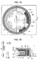
- Figs. 1A and 1B are structural views of a vibrating motor using an outer rotor type stepping motor according to an exemplary embodiment of the invention.
- Fig. 1A is a sectional view along line A-A of Fig. 1B
- Fig. 1B is a sectional view along line B-B of Fig. 1A
- a vibration motor 1 includes a rotating shaft having a third stator yoke 3c serving also as a bearing and a rotor frame 4.
- the diameter of the rotating shaft 2 is, for example, 0.8 mm
- the outer diameter of the third stator yoke 3c serving also as the bearing is, for example, 1.8 mm.
- the third stator yoke 3c serving also as the bearing made of a magnetic material which is an oilless metal, is formed into a substantially cylindrical shape, (1) rotatably guides most of the side of the rotating shaft 2, (2) constitutes a part of a magnetic path through which the generated magnetic flux of a coil is transmitted, and (3) rotatably supports the vicinity of a fixed base of the rotor frame 4.
- a stator yoke 3 includes, in Fig. 1B, an upper first stator yoke 3a, a lower second stator yoke 3b, and the third stator yoke 3c serving also as the bearing.
- the third stator yoke 3c serving also as the bearing, as shown in Fig. 1A, a center opening 3d of the first stator yoke 3a and the second stator yoke is fitted and fixed to small-diameter stepped parts 3e in the vicinities of upper and lower ends.
- the first stator yoke 3a and the second stator yoke 3b are made of a magnetic material, and as shown in the plan view of Fig. 1 A, the whole is formed into a cup shape having an opening at the center, five substantially U-shaped cuts 3f are formed on the circumference to be opened at equal intervals, and the remaining parts between the substantially U-shaped cuts 3f are pole teeth 3g.
- the first stator yoke 3a and the second stator yoke 3b which are formed in this way, are disposed vertically so that the mutual pole teeth 3g (the first pole teeth (3g-1, 3g-3, etc.) and second pole teeth (3g-2, 3g-4, etc.)) engage with each other in a comb teeth shape.
- a coil bobbin 6 housing a stator coil 5 is provided between the first stator yoke 3a and the second stator yoke 3b.
- the stator yoke 3 including the first stator yoke 3a, the second stator yoke 3b and the third stator yoke 3c is disposed so as to surround the periphery of the annular stator coil 5.
- the coil bobbin 6 is made of a resin, has a C-shaped section, and is constructed to be annular when viewed on a plan view (not shown).
- An arbitrary wire rod can be used for the stator coil 5.
- a self-bonding wire is desirable.
- the stator coil 5 is formed as an integrated annular coil in such a manner that the self-bonding wire is wound around the annular coil bobbin 6, and heat is applied to fusion-bond the insulating coating. That is, the stator coil is constructed by winding the self-bonding wire and fusion-bonding it. By the fusion-bonding treatment of the insulating coating, the imbalance of arrangement between the wound windings is suppressed, and uniformity of the arrangement can be realized.
- the rotor frame 4 is made of a metallic material. Preferably, it is made of, for example, SUS (stainless) 303.
- the section of the rotor frame 4 has a C shape having an opening at the center. The whole is constructed into a cup shape including a substantially circular disk part 4b having an opening part 4a at the center and a cylindrical part 4c provided to stand on its periphery at right angles.
- the opening part 4a is fitted and fixed to a small-diameter stepped part 2a of the rotating shaft 2.
- the rotor frame 4 is provided to be spaced from the first stator yoke 3a.
- the vicinity of an attachment base part of the rotor frame 4 to the rotating shaft 2 is axially supported by a shaft direction end surface of the third stator yoke 3c serving also as the bearing.
- An arc-shaped eccentric weight 7 and at least two arc-shaped magnets 8a and 8b are provided on the inside surface of the cylindrical part 4c of the rotor frame 4.
- the eccentric weight 7 has a rectangular section equal to the sections of the magnets 8a and 8b shown in Fig. 1A, and when shown on a plan view, as shown in Fig. 1A, the eccentric weight is formed into a semi-arc shape.
- the center angle of the semi-arc shape is obtained in design, and in the case of embodiment 1, it is set to be 180 degrees.
- the eccentric weight 7 is made of a metal, such as tungsten alloy, which is not harmful, has atmosphere resistance and has large mass. Besides, the eccentric weight 7 may be made of a magnetic material, and the rotation torque can be raised by providing irregularities with the pole teeth pitch of the stator yoke at the inside in the radial direction.
- the magnet 8 is made of an arbitrary magnetic material. Preferably, it is made of a neodymium (Nd-Fe-B) alloy magnet, a bonded magnet (compound magnet formed by solidifying magnetic powder with a binder).
- the magnet 8 can be constructed of one magnet at minimum. In the case of one magnet, the construction is made such that magnetization is performed to provide multi-poles, and only one pole of the magnetized multi-poles has the effect of a commutating pole. That is, the construction is made by adopting such means that only one pole is shifted in pole pitch as compared with the other poles, or only one pole is made to have a different gap from the pole tooth and is shifted.
- a magnetic pole pair of a pair of an N pole and an S pole is made a unit, and the magnet 8 includes an arbitrary number of magnetic pole pairs.
- “one-pole magnetization” at the time when magnetization is explained means “magnetization of one magnetic pole pair”
- “multi-pole magnetization” means “magnetization of many magnetic pole pairs”.
- a mode in which three magnets each having one-pole magnetization are coupled to form one body is also included in the concept of "one arc-shaped magnet is magnetized to provide multi-poles".
- the magnet 8 can be constructed of plural magnets. In the case of embodiment 1, an example in which the magnet 8 includes plural magnets is described.
- the magnet 8 is divided in two, one of them is formed as the rotor magnet 8a, and the other is formed as the commutating-pole magnet 8b.
- the size of the magnet 8 is determined according to the torque required.
- the magnetization direction of the magnet 8 can be set to be an arbitrary direction.
- magnetization is performed to have NS or SN in the radial direction. That is, the magnet 8 has a monopole-magnetized surface (an N pole surface or an S pole surface).
- the magnet 8 including the rotor magnet 8a and the commutating-pole magnet 8b are magnetized in the radial direction, the width of the magnetic pole, that is, the arc length in the case of embodiment 1 becomes short (as compared with one in which magnetization is performed in the circumferential direction), plural magnets can be closely disposed in the circumferential direction, and the magnetization at a fine pitch becomes easy. Thus, a step width can be made narrow, and accordingly, the outer diameter of the vibrating motor can be made small. Since the magnet including the rotor magnet 8a and the commutating-pole magnet 8b is magnetized in the radial direction, the adjustment of a stop position becomes easy.
- the rotor magnet 8a has a rectangular section shown in Fig. 1B, and when shown on a plan view, it is formed into the arc shape as shown in Fig. 1 A.
- the rotor magnet 8a has an arc length corresponding to a pole teeth (for example, 3g-1, 3 g-2, ...) pitch of the stator yoke 3.
- the commutating-pole magnet 8b is formed to have the magnetic flux amount larger than the rotor magnet 8a, has the same section as the rotor magnet 8a, and is formed, when shown on the plan view, into the arc shape shown in Fig. 1A.
- the commutating-pole magnet 8b has the arc length narrower than the pole teeth pitch of the stator yoke 3, and functions to shift the stop position of the rotor 9 after the exciting current of the stator coil 5 is cut.
- the rotor 9 includes the rotating shaft 2, the rotor frame 4, the eccentric weight 7, and the magnet 8.
- the volume ratio of the eccentric weight 7 to the magnet 8 is, for example, about 2:1.
- a case 10 is made of a nonmagnetic metal, for example, SUS (stainless) 303, and has a C-shaped section, and the whole is constructed to have a cup shape made up of a disk part 10a and a cylindrical part 10b provided to stand on its periphery at right angles. Projections 10c to be fixed to an interface board 11 by soldering or welding are provided on the end surface of the cylindrical part 10b.
- the case 10 is formed to have, for example, a diameter of 10 mm and a height of slightly less than 3 mm.
- the interface board 11 is constructed such that an insulating film is provided on a metal plate, and a necessary wiring (feeder to a coil, etc.) and openings 11a for fitting the projections 10c are formed thereon.
- the second stator yoke 3b is fixed to the interface board 11 through the insulating film, and the projections 10c of the end surface of the cylindrical part 10b of the case 10 are fitted in the openings 11a and are soldered from the back surface.
- An external control circuit, a power supply and the like are connected to the wiring.
- the vibrating motor of the invention is controlled with speed characteristics such as acceleration, constant speed and deceleration.
- a slow start is made and the speed is increased up to the constant speed in, for example, 0.3 to 0.5 seconds.
- rotation is made at, for example, ten thousand rpm at which bodily sensation is good.
- an acceleration detector of a human being is a Pacini corpuscle.
- the frequency of vibration easily sensed by this organ is in the range of about 100 to 300 Hz.
- the range of vibration and the range of acceleration in which vibration is certainly sensed and uncomfortable feeling is less, it is said that the frequency is in the range of 100 to 300 Hz and the acceleration is in the range of 0.2 to 2 G (gravitational acceleration).
- the speed reaches the maximum speed. It is preferable that the falling deceleration time is as short as possible.
- the acceleration is in the middle of speed increase to the maximum speed (constant speed), vibration by step driving does not become a serious problem.
- the deceleration is a process for the stop, the vibration becomes a problem.
- the exciting time depends on the maximum drive current.
- the maximum drive current is made a large current for high speed driving.
- the maximum drive current is made a small current, and a stop with less vibration is performed.
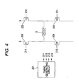
- FIG. 4 is a diagram of a circuit for controlling the drive current of the coil according to the invention.
- a drive timing signal of a coil for a single-phase stepping motor of Fig. 4 is generated by a timing generation circuit, and is supplied to P-type MOSFETs 202 and 203 and N-type MOSFETs 204 and 205.
- a control signal 211 of the P-type MOSFET 202 and a control signal 214 of the N-type MOSFET 205 respectively come to have the ON potential, and current in one direction is supplied to the coil 5.
- a control signal 212 of the P-type MOSFET 203 and a control signal 213 of the N-type MOSFET 204 come to have the ON potential, and current in the reverse direction is supplied to the stator coil 5.
- the same control is repeated.
- a switching element of a different transistor or the like can also be used.
- the pulse signal for control is controlled by pulse width modulation (PWM), pulse frequency modulation (PFM), or pulse amplitude modulation (PAM) in order to perform the speed control.
- PWM pulse width modulation
- PFM pulse frequency modulation
- PAM pulse amplitude modulation
- the vibrating motor of the invention uses the single-phase stator coil 5, after the drive current to the stator coil 5 is cut (OFF), the rotor must be moved so that the rotation direction becomes the same direction at the time of next starting.
- the magnet 8 is formed into an arc shape on the circumference around the rotating shaft, and such magnets are disposed at, for example, two or more places. At that time, in order that the rotation direction can be determined, a combination of following means (1) to (4) is adopted.
- the magnetization of the rotor magnet 8a is such that in an area 8a-1, the N pole is formed at the inside in the radial direction, and the S pole is formed at the outside, whereas in an area 8a-2, the S pole is formed at the inside in the radial direction, and the N pole is formed at the outside.
- the magnetic path is formed in the path ofN pole of the area 8a-1 ⁇ S pole of the area 8a-1 ⁇ N pole of the area 8a-2 ⁇ S pole of the area 8a-2 ⁇ N pole of the pole tooth 3g-2 ⁇ S pole of the pole tooth 3g-1 ⁇ N pole of the area 8a-1.
- the commutating-pole magnet 8b is disposed to be shifted to a pitch inconsistent with that pitch, in the case of embodiment 1, to a pitch corresponding to the position shifted in the rotation direction (clockwise direction) by a minute distance from the half of the pole tooth 3g-3 of the first stator yoke 3a, and the position shifted in the rotation direction (clockwise direction) by a minute distance from the half of the pole tooth 3g-4 of the second stator yoke 3b.
- the commutating-pole magnet 8b is also magnetized similarly to the rotor magnet 8a. That is, for example, the S pole is formed at the inside in the radial direction, and the N pole is formed at the outside in the radial direction to be opposite thereto.
- the magnetic flux amount of the commutating-pole magnet 8b is set to be larger than the magnetic flux amount of the rotor magnet 8a.
- the S pole of the commutating-pole magnet 8b is moved to the magnetically stable position opposite to the pole tooth 3g-4.
- the rotor magnet 8a coupled with the rotor frame 4 is similarly moved in the rotation direction.
- the stop state is held in this state.
- the direction of the final drive current is stored as data, and based on the data, the direction of the drive current is determined so that the rotation direction becomes the same direction.
- means adopted for the stop position control is as follows:
- Figs. 2A and 2B are explanatory views of another stop position control means of an exemplary embodiment of the invention.
- Fig. 2A is an explanatory view of the above means (1) for causing the rotor magnet to have the magnetization pitch different from the pole teeth pitch
- Fig. 2B is an explanatory view of the above means (2) for causing the magnetization pitch and the gap to vary.
- the rotor magnet 8 is formed by magnetizing one arc-shaped magnet to have multi-poles.
- Fig. 2A shows a state in which the stator coil is driven by applying current.
- the N pole of the pole tooth and the S pole of the rotor magnet are opposite to each other.
- the rotor magnet is moved by a distance (L1) in the rotation direction of an arrow so that adjacent magnetic poles of the rotor magnet are put in a magnetically stable state between the adjacent magnetic poles and the magnetic resistance becomes minimum.
- the magnetic pitch of the three poles of the continuous rotor magnets 8a1, 8a2 and 8a3 are made to correspond to the magnetic pole pitch of less than three protruding poles of the stator yoke, and a protrusion T to cause the gap between both (the pole tooth 3g-1 and the rotor magnet 8a1) to vary is provided in a remaining partial area of the inside area of the magnetic pole 8a1 except the center part.
- the rotor magnet is moved by a predetermined distance (L2) so that the rotor magnet 8a1 is put in a magnetically stable state, that is, the projection T of the rotor magnet 8a1 goes to the center of the magnetic pole 3g-1.
- L2 a predetermined distance
- stop position control means for determining a rotation direction:
- Figs. 3A and 3B are explanatory views of the stop position control means in the stator yoke of an exemplary embodiment of the invention.
- Fig. 3A is an explanatory view of the above means (1) for causing the pole teeth shapes of the stator yoke to be asymmetric
- Fig. 3B is an explanatory view of the means (2) for shifting the pole teeth phases of the two stator yokes.
- the rotor magnet has three poles (stage of Y4), the pole teeth (stages of Y2 + Y3) are formed to be asymmetric, X1 to X6 denote positions on a circumference in the rotation direction, and the pole teeth are shown at the stage of Y2 of the horizontal stage and the stage of Y3.
- the pole teeth Stages of Y2 + Y3
- the rotor magnet is magnetically held at the position where the magnetic poles are as indicated at the stage of Y4.
- the rotor magnet is formed to have three poles (stage of Y3) at an equal pitch, the phases of the pole teeth (stage of Y2) are shifted, X1 to X4 denote positions on the circumference in the rotation direction, and the pole teeth are shown at the stage of Y2.
- the pole teeth (stage of Y2) are excited by the drive current of the stator coil to have the polarities at the stage of Y2, the rotor magnet is magnetically held at the position where the magnetic poles are as indicated at the stage of Y3.
- the stage of Y1 indicates positions of magnetic poles of the rotor magnet corresponding to the magnetic poles of the pole teeth at the time the current is applied to the stator coil.
- means for moving the position of the rotor so as to enable rotation in which the rotation direction is made the initial direction at the next starting that is, means for moving the rotor into a magnetically stable state can be adopted.
- the outer rotor type incorporates the eccentric weight in the same outermost rotation area as the magnet, the housing space of the eccentric weight can be shared with the magnet. Since the eccentric weight is disposed at the outermost side, the radius becomes long, strong vibration can be generated, and parts exposed to the outside can be removed. Besides, since the stepping motor has no brush, similarly to another brushless motor, the necessity of maintenance almost disappears, and its lifetime becomes long.
- the vibration amount can be linearly adjusted, and the stop time can be shortened.
- the third stator yoke to couple the first stator yoke with the second stator yoke is made of a magnetic material so that it serves also as the bearing, the occurrence of magnetic leakage flux is suppressed, the magnetic path passing through the bearing can be constructed, and the generated magnetic flux can be effectively used.
- the magnet is formed into the arc shape on the circumference with the rotating shaft as the center, and is disposed at two or more places. At that time, the combination of the following means of (1) to (4) is adopted so that the rotation direction can be determined.
- the magnet is magnetized in the radial direction. In that case, plural magnets are closely disposed in the circumferential direction. By this, magnetic pole arrangement at a fine pitch becomes easy. Further, the arrangement of an odd number of poles becomes possible, the space is effectively used, and efficient motor design becomes possible.
- the eccentric weight is made of a magnetic material, and the irregularities having a pitch substantially equal to the yoke pole teeth are provided on the surface opposite to the yoke. By this, the efficiency can be increased.
- stator yoke With respect to the stator yoke, the pole teeth phases of two stator yokes are shifted or the pole teeth shapes of the stator yoke are made asymmetric, so that the rotation direction can be determined.
- the gap between the pole teeth of the stator yoke and the rotor magnet is made irregular, so that the rotation direction can be determined.
- the self-bonding wire is used for the stator coil. By this, reduction in thickness, improvement in quality (improvement in swelling), high density winding (aligned winding) are achieved.
- Figs. 5A and 5B are structural views of an inner rotor type vibrating motor of an exemplary embodiment of the invention.
- Fig. 5A is a sectional view along line C-C of Fig. 5B
- Fig. 5B is a sectional view along line D-D of Fig. 5A.
- a bearing 12 is vertically provided on an interface board 21 like the one shown in embodiment 1, a cylindrical rotating shaft 19 is rotatably provided on the bearing 12, a supporting body 22 is fixed to the rotating shaft 19, and a magnet 18 is provided at the tip of the supporting body 22.
- the magnet 18 includes a rotor magnet 18a and a commutating-pole magnet 18b.
- the magnet 18 can be basically constructed of one or more magnets.
- the magnetization of the rotor magnet 18a and the commutating-pole magnet 18b; the magnetic pole pitch and the like are constructed similarly to the case of embodiment 1.
- a stator is arranged such that a single-phase annular stator coil 15 is provided in a coil bobbin 16 which has a C-shaped section and is annular when shown on a plan view, a stator yoke 13 is provided so as to surround the coil bobbin 16, and pole teeth 13g of the stator yoke 13 are combined in a comb teeth shape and are disposed.
- the stator yoke 13 is attached to the same interface board 21 as the case of embodiment 1.
- the stator yoke 13 includes, as shown in Fig. 5B, an upper first stator yoke 13 a, a lower second stator yoke 13b, and a third stator yoke 13c coupling both.
- Each of the first stator yoke 13a and the second stator yoke 13b has a pole tooth at the inside in the radial direction.
- the shape of the pole tooth can be set to be arbitrary.
- a rotor frame 14 is fixed to the rotating shaft 19.
- the rotor frame 14 is made of a metallic material. Preferably, it is made of, for example, SUS (stainless) 303.
- the section of the rotor frame 4 has a C shape having an opening 14c at the center. The whole is constructed into a cup shape having a substantially circular disk part 14a having the opening 14c at the center and a cylindrical part 14b provided to stand on its periphery at right angles.
- An eccentric weight 17 is fixed to the inside of the cylindrical part 14b.
- the eccentric weight 17 is formed into an arc shape with a center angle of 180 degrees.
- the center angle of the eccentric weight 17 can be arbitrarily designed.
- the eccentric weight 17 is disposed outside the stator yoke 13 in the radial direction to provide a gap between it and the stator yoke 13.
- the eccentric weight 17 is made of a magnetic material, irregularities with the pole teeth pitch of the stator yoke 13 is provided at the inside in the radial direction, while pole teeth opposite to the inside pole teeth are formed at the outside of the stator yoke 13 in the radial direction, and the rotation torque can be improved.
- a case 20 equal to that shown in embodiment 1 is disposed outside the rotor frame 14 through the gap so as to cover the rotor frame 14.
- the magnet and the pole teeth can be freely designed without considering the eccentric weight.
- the number of the pole teeth can be increased, and as a result, the number of steps is increased, and precise control becomes possible.
- the magnet, the stator yoke, and the eccentric weight are arranged in a line, and a flat and thin structure can be made.
- a vibration generating device for incoming call indication is increased in number.
- the vibrating motor in general, although a feeding terminal of a vibrating motor is provided on a main board, the vibrating motor itself is directly fixed to a frame. A fixed place is an end opposite to the interface connector side and in the vicinity of an antenna. Since a housing space becomes a narrow space between the main board and the frame, it is necessary that an occupied space of the vibrating motor has an efficient shape so that it is contained in the narrow space.
- the portable terminal apparatus of the invention uses the above vibrating motor, while the vibrating motor is contained in the efficient small occupied space of the flat cylindrical shape, the strong vibration required by the apparatus can be generated.
Landscapes
- Engineering & Computer Science (AREA)
- Power Engineering (AREA)
- Physics & Mathematics (AREA)
- Electromagnetism (AREA)
- Mechanical Engineering (AREA)
- Manufacturing & Machinery (AREA)
- Signal Processing (AREA)
- Apparatuses For Generation Of Mechanical Vibrations (AREA)
- Connection Of Motors, Electrical Generators, Mechanical Devices, And The Like (AREA)
- Permanent Magnet Type Synchronous Machine (AREA)
- Iron Core Of Rotating Electric Machines (AREA)
Applications Claiming Priority (1)
| Application Number | Priority Date | Filing Date | Title |
|---|---|---|---|
| JP2004257605A JP3942184B2 (ja) | 2004-09-03 | 2004-09-03 | 振動モータおよびそれを用いた携帯端末機器 |
Publications (2)
| Publication Number | Publication Date |
|---|---|
| EP1633034A2 true EP1633034A2 (fr) | 2006-03-08 |
| EP1633034A3 EP1633034A3 (fr) | 2007-03-07 |
Family
ID=35004342
Family Applications (1)
| Application Number | Title | Priority Date | Filing Date |
|---|---|---|---|
| EP05018179A Withdrawn EP1633034A3 (fr) | 2004-09-03 | 2005-08-22 | Moteur vibrant et terminal portable avec un tel moteur |
Country Status (5)
| Country | Link |
|---|---|
| US (1) | US20060049705A1 (fr) |
| EP (1) | EP1633034A3 (fr) |
| JP (1) | JP3942184B2 (fr) |
| KR (1) | KR100848413B1 (fr) |
| CN (1) | CN100530912C (fr) |
Cited By (2)
| Publication number | Priority date | Publication date | Assignee | Title |
|---|---|---|---|---|
| GB2491880A (en) * | 2011-06-16 | 2012-12-19 | Imra Europe Sas | Non-uniformly spaced claw-pole stator |
| CN119448598A (zh) * | 2023-08-01 | 2025-02-14 | 青岛海尔空调器有限总公司 | 用于电机定子的加工方法及加工装置、电机 |
Families Citing this family (14)
| Publication number | Priority date | Publication date | Assignee | Title |
|---|---|---|---|---|
| JP2008182796A (ja) * | 2007-01-23 | 2008-08-07 | Minebea Motor Manufacturing Corp | ステッピングモータ |
| JP4295329B2 (ja) | 2007-03-30 | 2009-07-15 | ミネベアモータ株式会社 | ステッピングモータ |
| JP2008271748A (ja) * | 2007-04-24 | 2008-11-06 | Minebea Motor Manufacturing Corp | ラジアル型ステッピングモータ |
| JP2008283810A (ja) * | 2007-05-11 | 2008-11-20 | Minebea Motor Manufacturing Corp | 振動発生用ステッピングモータ |
| JP4837020B2 (ja) | 2008-11-25 | 2011-12-14 | 株式会社東芝 | 永久磁石モータおよび洗濯機 |
| TWI440283B (zh) | 2011-07-26 | 2014-06-01 | Sunonwealth Electr Mach Ind Co | 馬達控制方法 |
| JP5373882B2 (ja) * | 2011-12-21 | 2013-12-18 | 敏秀 北 | 電動モーター |
| JP2015047525A (ja) * | 2013-08-30 | 2015-03-16 | アルプス電気株式会社 | 振動発生装置 |
| KR102331602B1 (ko) * | 2015-04-06 | 2021-11-30 | 엘지전자 주식회사 | 의류처리장치 |
| DE102018210163B4 (de) * | 2018-06-22 | 2026-01-29 | Hs Products Engineering Gmbh | Statorvorrichtung, Elektroflachmotor und Verfahren zum Herstellen einer Statorvorrichtung |
| WO2020184108A1 (fr) * | 2019-03-12 | 2020-09-17 | アルプスアルパイン株式会社 | Dispositif d'entraînement magnétique et dispositif de fonctionnement |
| DE102019108093A1 (de) * | 2019-03-28 | 2020-10-01 | Brose Fahrzeugteile SE & Co. Kommanditgesellschaft, Coburg | Vibrationsvorrichtung |
| CN110971018A (zh) * | 2019-12-03 | 2020-04-07 | 中信戴卡股份有限公司 | 一种安装于旋转物体的发电机 |
| CN114257037B (zh) * | 2020-09-21 | 2023-08-04 | 北京小米移动软件有限公司 | 一种振动组件 |
Citations (2)
| Publication number | Priority date | Publication date | Assignee | Title |
|---|---|---|---|---|
| JPH09252573A (ja) | 1996-03-15 | 1997-09-22 | Citizen Watch Co Ltd | ステップモータ |
| JP2004257605A (ja) | 2003-02-25 | 2004-09-16 | Toto Ltd | 浴室換気暖房乾燥装置 |
Family Cites Families (31)
| Publication number | Priority date | Publication date | Assignee | Title |
|---|---|---|---|---|
| NL8402113A (nl) * | 1984-07-03 | 1986-02-03 | Kinetron Bv | Stelsel voor elektrische voeding van draagbare miniatuur-energieverbruikers. |
| US4728837A (en) * | 1984-11-30 | 1988-03-01 | Combustion Engineering, Inc. | Variable speed, variable motion, electrically operated vibrator for screening machinery |
| JPH03230738A (ja) * | 1990-02-06 | 1991-10-14 | Mitsubishi Electric Corp | 電動機 |
| DE69323314T2 (de) * | 1992-08-12 | 1999-06-17 | Seiko Epson Corp., Tokio/Tokyo | Steuerverfahren eines bürstenlosen gleichstrommotor |
| JPH0837753A (ja) * | 1992-10-14 | 1996-02-06 | Tokyo Parts Ind Co Ltd | 偏心電機子鉄心を有する小型振動モータ |
| USRE37576E1 (en) * | 1993-02-22 | 2002-03-12 | General Electric Company | Single phase motor with positive torque parking positions |
| US5773908A (en) * | 1993-02-22 | 1998-06-30 | General Electric Company | Single phase motor with positive torque parking positions |
| DE4427337A1 (de) * | 1994-08-02 | 1996-02-08 | Ako Werke Gmbh & Co | Einphasen-Synchronmotor |
| JP3460912B2 (ja) * | 1996-10-18 | 2003-10-27 | ミネベア株式会社 | モータ構造 |
| US5942833A (en) * | 1998-09-29 | 1999-08-24 | Tokyo Parts Industrial Co., Ltd. | Flat coreless vibrator motor |
| JP4276315B2 (ja) * | 1998-11-17 | 2009-06-10 | シチズン電子株式会社 | 電磁型発音体 |
| US6996228B1 (en) * | 1999-03-10 | 2006-02-07 | Nokia Mobile Phones, Ltd. | Motor for generating vibrational signal |
| JP3159202B2 (ja) * | 1999-03-15 | 2001-04-23 | 松下電器産業株式会社 | 偏平振動モータ |
| US6326711B1 (en) * | 1999-09-07 | 2001-12-04 | Tokyo Parts Industrial Co., Ltd. | DC brushless motor having eccentric rotor |
| KR100360126B1 (ko) * | 2000-01-04 | 2002-11-08 | 주식회사 삼부커뮤닉스 | 바이브레이터 |
| JP3159212B1 (ja) * | 2000-01-28 | 2001-04-23 | 松下電器産業株式会社 | ブラシレス振動モータ |
| JP2001300425A (ja) * | 2000-02-14 | 2001-10-30 | Tokyo Parts Ind Co Ltd | 径方向空隙式回転ヨーク型ブラシレス振動モータ |
| CN1367569A (zh) * | 2001-01-24 | 2002-09-04 | 日本胜利株式会社 | 振动型无刷电动机 |
| US6636007B2 (en) * | 2001-03-12 | 2003-10-21 | Sunonwealth Electric Machine Industry Co., Ltd. | DC brushless vibration motor |
| JP2002271879A (ja) * | 2001-03-13 | 2002-09-20 | Citizen Electronics Co Ltd | 多機能型音響装置 |
| US20020163265A1 (en) * | 2001-05-04 | 2002-11-07 | Sunonwealth Electric Machine Industry Co., Ltd. | Miniature vibration motors structure |
| JP3790438B2 (ja) * | 2001-05-07 | 2006-06-28 | 建準電機工業股▲分▼有限公司 | 電動機のステータ組の改良構造 |
| US6465921B1 (en) * | 2001-05-10 | 2002-10-15 | Sunonwealth Electric Machine Industry Co., Ltd. | Assembling structure of a miniature vibration motor |
| JP2003088076A (ja) * | 2001-09-03 | 2003-03-20 | Jianzhun Electric Mach Ind Co Ltd | 直流ブラシレスモーター |
| US6897579B2 (en) * | 2001-09-28 | 2005-05-24 | Canon Kabushiki Kaisha | Motor |
| KR100560760B1 (ko) * | 2002-03-14 | 2006-03-14 | 자화전자 주식회사 | 통신기기용 음향장치와 진동모터의 결합형 구조 |
| KR200284572Y1 (ko) | 2002-04-22 | 2002-08-13 | 고시진 | 이동통신기기 및 소형 게임기용 진동모터 내장형 스피커 |
| EP1359656B1 (fr) * | 2002-04-30 | 2017-12-20 | Johnson Electric Switzerland AG | Moteur électrique |
| KR200289955Y1 (ko) | 2002-06-07 | 2002-09-19 | 대성전기공업 주식회사 | 편평형 진동모터 |
| EP1420507B1 (fr) * | 2002-11-16 | 2008-01-09 | Minebea Co., Ltd. | Moteur miniature avec rotor aux aimants permanents |
| US20040104631A1 (en) * | 2002-12-03 | 2004-06-03 | Tokyo Parts Industrial Co., Ltd. | Brushless vibration motor |
-
2004
- 2004-09-03 JP JP2004257605A patent/JP3942184B2/ja not_active Expired - Fee Related
-
2005
- 2005-08-22 EP EP05018179A patent/EP1633034A3/fr not_active Withdrawn
- 2005-09-01 US US11/216,067 patent/US20060049705A1/en not_active Abandoned
- 2005-09-02 KR KR1020050081545A patent/KR100848413B1/ko not_active Expired - Fee Related
- 2005-09-02 CN CNB2005100985786A patent/CN100530912C/zh not_active Expired - Fee Related
Patent Citations (2)
| Publication number | Priority date | Publication date | Assignee | Title |
|---|---|---|---|---|
| JPH09252573A (ja) | 1996-03-15 | 1997-09-22 | Citizen Watch Co Ltd | ステップモータ |
| JP2004257605A (ja) | 2003-02-25 | 2004-09-16 | Toto Ltd | 浴室換気暖房乾燥装置 |
Cited By (3)
| Publication number | Priority date | Publication date | Assignee | Title |
|---|---|---|---|---|
| GB2491880A (en) * | 2011-06-16 | 2012-12-19 | Imra Europe Sas | Non-uniformly spaced claw-pole stator |
| GB2491880B (en) * | 2011-06-16 | 2015-04-01 | Imra Europe Sas | Claw pole stator |
| CN119448598A (zh) * | 2023-08-01 | 2025-02-14 | 青岛海尔空调器有限总公司 | 用于电机定子的加工方法及加工装置、电机 |
Also Published As
| Publication number | Publication date |
|---|---|
| CN1747292A (zh) | 2006-03-15 |
| JP2006074949A (ja) | 2006-03-16 |
| EP1633034A3 (fr) | 2007-03-07 |
| CN100530912C (zh) | 2009-08-19 |
| KR20060050954A (ko) | 2006-05-19 |
| US20060049705A1 (en) | 2006-03-09 |
| KR100848413B1 (ko) | 2008-07-28 |
| JP3942184B2 (ja) | 2007-07-11 |
Similar Documents
| Publication | Publication Date | Title |
|---|---|---|
| EP1633034A2 (fr) | Moteur vibrant et terminal portable avec un tel moteur | |
| US7271516B2 (en) | Stepping motor for generating vibration | |
| US6636007B2 (en) | DC brushless vibration motor | |
| JP2007006688A (ja) | 小型dcモータ | |
| JP4383058B2 (ja) | リラクタンスモータ | |
| US6674202B2 (en) | Eccentric commutator for vibrator motor | |
| US7719150B2 (en) | Vibration-generating stepping motor | |
| JP3560601B1 (ja) | モールド型偏心ロータと同ロータを備えた軸方向空隙型コアレス振動モータ | |
| KR100377562B1 (ko) | 편평형 코아리스 진동 모터 | |
| JP3472761B2 (ja) | 小型ブラシレス振動モータ | |
| JP2005102373A (ja) | 振動モータ | |
| JP2007185095A (ja) | 振動モータおよびそれを用いた携帯端末機器 | |
| JPH05304743A (ja) | 永久磁石ロータを慣性体とした振動モータ | |
| US20080278024A1 (en) | Radial stepping motor | |
| JP2005012935A (ja) | モールド型偏心ロータと同ロータを備えた軸方向空隙型コアレス振動モータ | |
| JP2005051945A (ja) | モータ用電機子、同電機子を備えた軸方向空隙型モータ | |
| JPH0678506A (ja) | ラジアル型アウターロータ方式ブラシレスモータ | |
| JP2004180446A (ja) | 扁平型ステッピングモータ | |
| JP2000069733A (ja) | 扁平型振動発生モータ | |
| KR100797279B1 (ko) | Dc 무브러시 진동 모터 | |
| JP3436573B2 (ja) | マイクロモータ | |
| JP4565133B2 (ja) | インナーロータ型振動モータ | |
| JP2005051996A (ja) | 振動モータ | |
| KR200222022Y1 (ko) | 편평형 코아리스 진동 모터 | |
| JP2004201420A (ja) | 円盤形偏心ロータと同ロータを備えた扁平コアレス振動モータ |
Legal Events
| Date | Code | Title | Description |
|---|---|---|---|
| PUAI | Public reference made under article 153(3) epc to a published international application that has entered the european phase |
Free format text: ORIGINAL CODE: 0009012 |
|
| AK | Designated contracting states |
Kind code of ref document: A2 Designated state(s): AT BE BG CH CY CZ DE DK EE ES FI FR GB GR HU IE IS IT LI LT LU LV MC NL PL PT RO SE SI SK TR |
|
| AX | Request for extension of the european patent |
Extension state: AL BA HR MK YU |
|
| PUAL | Search report despatched |
Free format text: ORIGINAL CODE: 0009013 |
|
| AK | Designated contracting states |
Kind code of ref document: A3 Designated state(s): AT BE BG CH CY CZ DE DK EE ES FI FR GB GR HU IE IS IT LI LT LU LV MC NL PL PT RO SE SI SK TR |
|
| AX | Request for extension of the european patent |
Extension state: AL BA HR MK YU |
|
| AKX | Designation fees paid | ||
| STAA | Information on the status of an ep patent application or granted ep patent |
Free format text: STATUS: THE APPLICATION IS DEEMED TO BE WITHDRAWN |
|
| 18D | Application deemed to be withdrawn |
Effective date: 20070908 |
|
| REG | Reference to a national code |
Ref country code: DE Ref legal event code: 8566 |