EP1633200B1 - Dispensing device for foodstuff, in particular ice cream - Google Patents
Dispensing device for foodstuff, in particular ice cream Download PDFInfo
- Publication number
- EP1633200B1 EP1633200B1 EP03817063A EP03817063A EP1633200B1 EP 1633200 B1 EP1633200 B1 EP 1633200B1 EP 03817063 A EP03817063 A EP 03817063A EP 03817063 A EP03817063 A EP 03817063A EP 1633200 B1 EP1633200 B1 EP 1633200B1
- Authority
- EP
- European Patent Office
- Prior art keywords
- container
- holder
- dispensing device
- delivery position
- anyone
- Prior art date
- Legal status (The legal status is an assumption and is not a legal conclusion. Google has not performed a legal analysis and makes no representation as to the accuracy of the status listed.)
- Expired - Lifetime
Links
- 235000015243 ice cream Nutrition 0.000 title claims description 10
- 230000000284 resting effect Effects 0.000 claims description 2
- 238000003780 insertion Methods 0.000 description 6
- 230000037431 insertion Effects 0.000 description 6
- 238000007599 discharging Methods 0.000 description 5
- 238000010276 construction Methods 0.000 description 3
- 239000007787 solid Substances 0.000 description 2
- 230000001154 acute effect Effects 0.000 description 1
- RKTYLMNFRDHKIL-UHFFFAOYSA-N copper;5,10,15,20-tetraphenylporphyrin-22,24-diide Chemical compound [Cu+2].C1=CC(C(=C2C=CC([N-]2)=C(C=2C=CC=CC=2)C=2C=CC(N=2)=C(C=2C=CC=CC=2)C2=CC=C3[N-]2)C=2C=CC=CC=2)=NC1=C3C1=CC=CC=C1 RKTYLMNFRDHKIL-UHFFFAOYSA-N 0.000 description 1
- 230000007797 corrosion Effects 0.000 description 1
- 238000005260 corrosion Methods 0.000 description 1
- 238000011161 development Methods 0.000 description 1
- 230000018109 developmental process Effects 0.000 description 1
- 230000002349 favourable effect Effects 0.000 description 1
- 230000009969 flowable effect Effects 0.000 description 1
- 235000013305 food Nutrition 0.000 description 1
- 238000009434 installation Methods 0.000 description 1
- 239000003562 lightweight material Substances 0.000 description 1
- 239000007788 liquid Substances 0.000 description 1
- 239000000463 material Substances 0.000 description 1
- 239000002184 metal Substances 0.000 description 1
- 235000011837 pasties Nutrition 0.000 description 1
- 239000000047 product Substances 0.000 description 1
- 239000012265 solid product Substances 0.000 description 1
- 230000001960 triggered effect Effects 0.000 description 1
- 239000008256 whipped cream Substances 0.000 description 1
Images


Classifications
-
- A—HUMAN NECESSITIES
- A23—FOODS OR FOODSTUFFS; TREATMENT THEREOF, NOT COVERED BY OTHER CLASSES
- A23G—COCOA; COCOA PRODUCTS, e.g. CHOCOLATE; SUBSTITUTES FOR COCOA OR COCOA PRODUCTS; CONFECTIONERY; CHEWING GUM; ICE-CREAM; PREPARATION THEREOF
- A23G9/00—Frozen sweets, e.g. ice confectionery, ice-cream; Mixtures therefor
- A23G9/04—Production of frozen sweets, e.g. ice-cream
- A23G9/22—Details, component parts or accessories of apparatus insofar as not peculiar to a single one of the preceding groups
- A23G9/28—Details, component parts or accessories of apparatus insofar as not peculiar to a single one of the preceding groups for portioning or dispensing
-
- A—HUMAN NECESSITIES
- A23—FOODS OR FOODSTUFFS; TREATMENT THEREOF, NOT COVERED BY OTHER CLASSES
- A23G—COCOA; COCOA PRODUCTS, e.g. CHOCOLATE; SUBSTITUTES FOR COCOA OR COCOA PRODUCTS; CONFECTIONERY; CHEWING GUM; ICE-CREAM; PREPARATION THEREOF
- A23G9/00—Frozen sweets, e.g. ice confectionery, ice-cream; Mixtures therefor
- A23G9/04—Production of frozen sweets, e.g. ice-cream
- A23G9/22—Details, component parts or accessories of apparatus insofar as not peculiar to a single one of the preceding groups
- A23G9/28—Details, component parts or accessories of apparatus insofar as not peculiar to a single one of the preceding groups for portioning or dispensing
- A23G9/281—Details, component parts or accessories of apparatus insofar as not peculiar to a single one of the preceding groups for portioning or dispensing at the discharge end of freezing chambers
- A23G9/283—Details, component parts or accessories of apparatus insofar as not peculiar to a single one of the preceding groups for portioning or dispensing at the discharge end of freezing chambers for filling containers with material
Definitions
- the invention relates to a dispensing device for a portioned foodstuff in accordance with the precharacterizing features of the independent claims.
- dispensing appliances in which a user can obtain a portion of the foodstuff by operating the dispensing appliance.
- the foodstuff may be a solid, flowable or pasty foodstuff.
- the invention is suitable in particular for ice cream or the like, for example whipped cream or other portioned liquids.
- a characteristic of such a dispensing device is that the user has to transport a container having therein the foodstuff to be dispensed into a delivery position in which the delivery of the foodstuff can take place.
- the insertion of the container in the delivery position is difficult because the construction of the holder for the container and of further parts of the dispensing device in the proximity of the delivery position limits the available space. Relatively great attentiveness and skill is therefore needed for the user in order to insert the container in the delivery position into the dispensing device.
- this insertion is difficult due to the fact that the construction of the dispensing device requires the delivery position to be at a certain distance from the operating side of the dispensing device and this distance makes it even more difficult to insert the container into the transfer position.
- a dispensing device of the previously described type has also already been proposed, in which different containers are to be inserted and to be removed in two delivery positions arranged one on top of the other.
- This dispensing device is designed to receive a storage container for the foodstuff in the region of the upper delivery position, the storage container being a package or casing which is filled with certain foodstuff which the user chooses before the operation and has to insert into the delivery position.
- the foodstuff can be, for example, a certain type of ice cream with which the package is filled.
- the dispensing device designed to receive a second (receiving) container, for example, an ice-cream cone into which the foodstuff from the first (storage) container is transferred, for example, by pushing the foodstuff out of the storage container by means of a ram and conveying it into the container.
- a second (receiving) container for example, an ice-cream cone into which the foodstuff from the first (storage) container is transferred, for example, by pushing the foodstuff out of the storage container by means of a ram and conveying it into the container.
- This dispensing device has the previously described difficulties in inserting and removing the first container (package) and/or also the second container (ice-cream cone).
- US 5,918,767 teaches a dispensing apparatus for dispensing a single serving of a viscous or semi-solid product from a container, the container comprising a base, a deformable portion and an outlet.
- the apparatus comprises deforming means movable to engage and deform the deformable portion to discharge product from the container through the outlet.
- GB 2,889,949 teaches an ice cream dispensing apparatus.
- JP 2003-070423 shows a device for extruding semi-solid food.
- the holder is connected to the support by an adjusting device and can be moved, while being in the adjusting device, between a delivery position for delivering the foodstuff and a removal position for inserting the container into and removing it from the holder. Therefore the container has not to be inserted in the delivery position, but rather in an auxiliary which is offset horizontally with respect to the latter and in which the insertion is simpler and easier because of the offset with respect to the delivery position, with the result that the user can insert the container into the holder with less attentiveness.
- the auxiliary position can be offset with respect to the delivery position towards a region which surrounds the delivery position in a curved manner from one side of the dispensing device, over the front operating side towards the other side. In this region, the auxiliary position can be offset laterally and also towards the operating side and also obliquely thereto. In all of these possible positions the auxiliary position is easier accessible to the user, as a result of which the previously described advantages arise when inserting the container into and removing it from the auxiliary position.
- a direction of movement which is arched in a curved manner between the auxiliary position and the delivery position is particularly suitable, specifically, in particular, if the arching axis or axis of rotation of the curved direction of movement is offset with respect to the delivery position towards the operating side and at the same time laterally.
- This makes it possible to arrange a hinge which makes the curved movement possible between the holder and the support offset, with respect to the delivery position towards the operating side and at the same time laterally.
- the rotary hinge can be arranged favourably in this position and with simple refinements. It should be taken into consideration here that a clearance is required on the section of movement between the auxiliary position and the delivery position, in which the container, which is held by the holder, can be moved.
- annular body of which the internal cross-sectional dimension forms an annular receiving opening for the container is particularly suitable for the holder with the result that the latter can be introduced into the annular body from above.
- the inner-upper edge of the annular body can form a resting element on which the container rests with an outer flange on its upper edge and is thereby prevented from slipping through the holder.
- two gripping clearances can be provided in the upper side of the holder, said clearances being arranged opposite to each other and in which two fingers of a user can be placed in order to easily and securely grasp the container.
- the adjusting device has a direction of movement which is curved in the form of a circular arch, it is advantageous to provide in the upper side of the holder, two further gripping clearances on the upper side of the holder which, with respect to the previously described gripping clearances, are arranged rotated by an angle which corresponds approximately to the angle which the holder rotates around as it moves from the delivery position into the auxiliary position.
- the container can also be grasped in an easy-to-handle manner in the auxiliary position.
- the dispensing appliance which is referred to in its entirety by 1, is a free-standing appliance which can be placed onto a standing surface 2 or the like and has a base 3 and a housing 4 which extends upwards from the said base and on whose front side 6, which faces the operating side 5, a dispensing device 7 for dispensing a foodstuff in portions, in particular ice cream, is arranged.
- the dispensing device 7 is situated below an upper front projection 8 of the housing 4, the lower side of which is referred to by 8a and is therefore situated in the region of a front recess 9 of the housing 4 which recess is arranged below the projection 8 and, for example, can extend continuously downwards.
- the dispensing device 7 comprises a holder 7a for a container 12 (indicated in Fig. 1 by chain-dotted lines) for the foodstuff and a support 7b which supports the holder 7a and is fastened to the housing 4 or to a frame (not illustrated) in the housing 4.
- At least one holding element 11 for holding the container 12 which is, for example, cup-shaped (see Fig. 1), is arranged on the holder 7a.
- the holder 7a has an annular body 13 which defines an annular receiving opening 14 for the container 12, into which the container 12 which is shaped e.g. such that it diverges upwards, can be inserted from above.
- the container 12 and the receiving opening 14 preferably have an essentially circular cross-sectional shape, whereby the container 12 fits with a clearance in the receiving opening 14 and rests with an outer flange 12a, which extends from the upper edge of the container, on the upper rim 14a of the receiving opening 14, which opening constitutes the holding element 11.
- the inner rim of the receiving opening 14 can present a recession (annular groove) in which the outer flange 12a of the container 12 rests such that the upper surface of the container 12 flushes with the upper contour of the holding element.
- the centering of the container 12 in the receiving opening 14 can be achieved by an engagement of the top region of the side walls of the container 12 and the rim of the receiving opening.
- the cross-sectional dimensions of the side walls and of the rim are set correspondingly.
- the centering of the container 12 in the receiving opening 14 can be achieved by an engagement of the outer flange 12a of the container 12 and the rim or the recession of the receiving opening 14.
- the receiving opening 14 is in a centre with respect to the annular body 13.
- the outer contour of the annular body 13 may be tetragonal or square, the annular body 13 and the holder 7a being in the form of a plate with an essentially flat upper and lower side.
- two gripping clearances 15a which are arranged lying opposite to each other and are formed by recesses are provided on the upper side of the holder 7a and in which, when the container 12 is being positioned in the holder 7a, two fingers of the operating hand grasping it on opposite sides can be placed and the container 12 can be advantageously deposited.
- the two fingers can likewise grip into the gripping clearances 15a and remove the container 12 in an easy-to-handle manner.
- An adjusting device 16 is arranged between the support 7b and the holder 7a and makes it possible to move the holder 7a essentially horizontally relative to the support 7b between a delivery position 17 (illustrated in Fig. 2) and an auxiliary position 18 (illustrated in Fig. 1).
- the delivery position 17 is situated in the central region of the recess 9 below the projection 8 and therefore close to the springing-back, vertical surface part 6a of the front side 6.
- the auxiliary position 18 is offset horizontally with respect to the delivery position 17, so that it is easier accessible to the user.
- a region B (Fig. 2) is appropriate for this, the said region surrounding the delivery position in a curved manner from the one side across the operating side 5 to the other side of the delivery position 17 or of the housing 4.
- auxiliary position 18 is accessible in a simple and easy-to-handle manner.
- Particularly favourable positions for the auxiliary position 18 are produced if the latter is offset with respect to the delivery position 17 towards the operating side 5, whereby it also may be offset laterally at the same time.
- the holder 7a With an offset of this type the holder 7a is situated closer to the operating side 5 than the delivery position 17, with the result that the positioning of a container 12 on the holder 7a is made substantially easier.
- the removal of the container 12 from the holder 7a which will also be described.
- the container 12 may be a package for the foodstuff, in particular ice cream, which, if appropriate after being opened, is positioned in the auxiliary position 18 on the holder 7a and is moved together with the holder 7a into the delivery position 17.
- a discharging device 19 is assigned to the delivery position 17 for discharging the container 12 downwards. This enables the foodstuff to be pressed downwards out of the container 12 and to be conveyed into a further container 21 which may be, for example, a cup or a cone wafer in which or with which the foodstuff is available for consumption.
- the holder 7a is firstly moved into the auxiliary position 18 in which the container 12 can be removed and disposed in an easy-to-handle manner.
- the discharging device 19 can be formed by a plunger 22 which is arranged coaxially with respect to the vertical central axis of the delivery position 17 and can be oscillated vertically between a starting position which is situated above the container 12 in the delivery position 17 and a discharging position, which plunges into the container 12, preferably as far as the base thereof, and back again.
- a drive 23 illustrated by way of indication
- the plunger 22 is guided vertically in a guide (not illustrated) and can be moved down and up again by the drive 23.
- the discharging movement of the plunger 22 can be triggered by a switch (not illustrated), and it is automatically ended when the plunger 22 is in its upper starting position again.
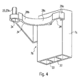
- the adjusting device 16 is formed by the holder 7a being mounted in a manner such that it can pivot to and fro in a hinge 25, having an approximately vertically directed hinge axis 25a, the hinge axis 25a likewise being offset with respect to the delivery position 17 into the region B.
- the hinge axis 25a is arranged on a straight line G which intersects the central axis of the delivery position and encloses, with the vertical central plane E of the dispensing device 7, an acute angle W of preferably approximately 45°.
- the hinge 25 can be arranged on one or the other side with respect to the vertical central plane. For left-handed operation, the hinge 25 is situated on the left side. For right-handed operation an arrangement on the right side is advantageous.
- the hinge axis 25a is situated in the region of a front and lateral corner 26 of the holder 7a in the auxiliary position. It is formed by a hinge pin 25b which protrudes from one hinge part and is mounted rotatably in a hinge opening 25c arranged on the other hinge part. This forms a plug-in connection 27 which makes an installation of the holder 7a possible by plugging it in from above and removal possible by removing it upwards. As a result, the holder 7a can be fitted and removed rapidly and in an easy-to-handle manner. This is particularly advantageous if the holder 7 is to be exchangeable.
- a plurality of holders 7a are preferably assigned to the dispensing device 7 and are matched to different containers 12.
- a specific exchange of the holders 7a therefore enables the dispensing device 7 to be matched to an appropriate container 12 in each case, with the result that this container 12 can be used appropriately and securely in the dispensing device 7.
- Different containers 12 and appropriated holders 7a can differ, for example, that the cross-sectional size or -shape of the container 12 and of the receiving opening 14 differs and is matched to one another.
- the container 12 is loaded (inserted) downwards during the previously described squeezing out of the container contents, it is advantageous, additionally to the hinge 25, to arrange further supporting elements 28 on the support 7b which support the holder 7a in the delivery position 17, preferably in a region B1 lying opposite to the hinge 25.
- Effective supporting is provided if two supporting elements 28, for example, the hinge 25 and the further supporting element 28 are provided lying opposite to each other.
- two supporting limbs 28a, 28b are provided, of which one is situated on the front side of the rear base part 7c of the support 7b.
- a supporting limb 28b is also provided which extends forwards from the base part 7c, supports the holder 7a on one side and in the front end region of which the hinge 25 is formed.
- a vertical recess 28c for the container 12 in the delivery position 17 is provided in the front side of the supporting limb 28a.
- the supporting limb 28b can be stabilized by a corner plate 28d.
- the holder 7a executes the shape of a circular arc during its movement between the positions 17, 18, in which case the auxiliary position 18 can be situated in the vertical central plane, as is also the case for the delivery position 17.
- Edge breaks 14b, 15c can be provided on the opening edge 14a and on the edges of the gripping clearances 15a, 15b.
- the container 12 may be a package which is to be opened for the delivery, for example, a casing.
- a gripping element 29 which can be grasped with the operating hand to move the holder 7a and is preferably arranged in the front region of the holder 7a.
- the gripping element 29 is formed by a laterally protruding pin which is arranged on the side lying laterally opposite the hinge 25.
- the stop 31 is formed by the rear part 7c protruding upwards over the rear supporting element 28 and thereby limiting the path of movement of the holder 7a on the rear side.
- the supporting element 28 has, in the end region of the supporting limb 28a, a cam depression 34 into which a corresponding cam element (not illustrated) engages on the holder 7a after running over an entry slope 35, whereby the cam element may also be biased.
- the engagement elements may also be assigned the other way around.
- the rear part 7c is fastened to the housing 4 by a fastening device (not illustrated), whereby it may be positioned in a housing recess 32.
- the holder 7a and the support 7b consist of a corrosion-resistant and preferably also lightweight material.
- a light metal or plastic is suitable for this.
- a hollow manner of construction is preferably also provided in order to save material and weight.
- chambers 33, 34 which are open on the lower side are provided in the rear part 7c and in the supporting limbs.
Landscapes
- Life Sciences & Earth Sciences (AREA)
- Chemical & Material Sciences (AREA)
- Engineering & Computer Science (AREA)
- Food Science & Technology (AREA)
- Polymers & Plastics (AREA)
- Confectionery (AREA)
- Devices For Dispensing Beverages (AREA)
Applications Claiming Priority (2)
| Application Number | Priority Date | Filing Date | Title |
|---|---|---|---|
| DE20308396U DE20308396U1 (de) | 2003-05-28 | 2003-05-28 | Abgabevorrichtung für ein Lebensmittel, insbesondere Speiseeis |
| PCT/EP2003/012297 WO2004105502A1 (en) | 2003-05-28 | 2003-11-04 | Dispensing device for foodstuff, in particular ice cream |
Publications (2)
| Publication Number | Publication Date |
|---|---|
| EP1633200A1 EP1633200A1 (en) | 2006-03-15 |
| EP1633200B1 true EP1633200B1 (en) | 2007-11-21 |
Family
ID=27635645
Family Applications (1)
| Application Number | Title | Priority Date | Filing Date |
|---|---|---|---|
| EP03817063A Expired - Lifetime EP1633200B1 (en) | 2003-05-28 | 2003-11-04 | Dispensing device for foodstuff, in particular ice cream |
Country Status (13)
| Country | Link |
|---|---|
| US (1) | US20060213922A1 (pt) |
| EP (1) | EP1633200B1 (pt) |
| CN (1) | CN1774176A (pt) |
| AU (1) | AU2003304157A1 (pt) |
| BR (1) | BR0318322A (pt) |
| CA (1) | CA2523697A1 (pt) |
| DE (2) | DE20308396U1 (pt) |
| ES (1) | ES2295706T3 (pt) |
| MX (1) | MXPA05012805A (pt) |
| PL (1) | PL378488A1 (pt) |
| TN (1) | TNSN05305A1 (pt) |
| WO (1) | WO2004105502A1 (pt) |
| ZA (1) | ZA200510471B (pt) |
Cited By (1)
| Publication number | Priority date | Publication date | Assignee | Title |
|---|---|---|---|---|
| WO2023052771A1 (en) * | 2021-09-29 | 2023-04-06 | Mcgill Technology Limited | Dispensing apparatus |
Families Citing this family (8)
| Publication number | Priority date | Publication date | Assignee | Title |
|---|---|---|---|---|
| US8491179B2 (en) | 2010-03-16 | 2013-07-23 | Vita-Mix Corporation | Cup holding assembly for a food mixing machine |
| CN103391735B (zh) * | 2011-01-31 | 2016-07-06 | 雀巢产品技术援助有限公司 | 具有方便胶囊装载和卸载的特征结构的饮料生产机 |
| ITBO20110070U1 (it) * | 2011-09-15 | 2013-03-16 | S P M Drink Systems Spa | Apparecchiatura per la preparazione di prodotti refrigerati |
| ITTV20130002A1 (it) * | 2013-01-07 | 2014-07-08 | Valmar Global Vse Za Sladoled D O O | Macchina mantecatrice per la produzione di gelato ed affini |
| WO2018183719A1 (en) | 2017-03-29 | 2018-10-04 | Mars, Incorporated | Device and method for dispensing product from a flexible package |
| CN111918558A (zh) | 2018-03-29 | 2020-11-10 | 荷兰联合利华有限公司 | 用于分配冷冻甜品的装置 |
| IT201800005682A1 (it) * | 2018-05-24 | 2019-11-24 | Contenitore a cartuccia per una macchina per la produzione di gelato | |
| US12295384B2 (en) * | 2019-09-04 | 2025-05-13 | Flavor Burst, Llc | Metering and calibration system and processes for frozen flowable confection freezer |
Family Cites Families (12)
| Publication number | Priority date | Publication date | Assignee | Title |
|---|---|---|---|---|
| GB700612A (en) * | 1950-03-03 | 1953-12-09 | Donald Albert Edward Beer | An apparatus for dispensing thin flat articles such as wafer biscuits |
| US2889949A (en) * | 1956-11-29 | 1959-06-09 | Nirenberg Morris | Ice cream dispensing apparatus |
| US4060367A (en) * | 1976-01-02 | 1977-11-29 | Ampco Foods Inc. | Drive mechanism for dough shaping apparatus |
| US4438683A (en) * | 1982-02-26 | 1984-03-27 | Prize Frize, Inc. | Apparatus for dispensing individual orders of a hot food product and components usable therewith |
| US5020698A (en) * | 1988-05-23 | 1991-06-04 | Crossley Jimmy L | Ice-cream ejector |
| DE9312009U1 (de) * | 1993-08-12 | 1993-10-07 | Robert Krups Gmbh & Co Kg, 42719 Solingen | Kaffeemaschine |
| EP1095901A1 (en) * | 1994-07-02 | 2001-05-02 | McGILL TECHNOLOGY LIMITED | Food dispensing apparatus |
| US5820892A (en) * | 1996-09-27 | 1998-10-13 | Lauer; James D. | Food extrusion assembly |
| ES2164556B2 (es) * | 1999-09-13 | 2003-05-01 | Unilever Nv | Envase contenedor de helado con dispensado por extrusion y maquina para la dispensacion correspondiente. |
| CA2288170C (en) * | 1999-10-25 | 2004-01-13 | Marcel Pineault | Method and tooling for food extrusion |
| KR100403888B1 (ko) * | 2001-07-28 | 2003-11-05 | 김희택 | 아이스크림 분배장치 |
| JP3929268B2 (ja) * | 2001-09-03 | 2007-06-13 | サンデン株式会社 | 半固形食品押出装置 |
-
2003
- 2003-05-28 DE DE20308396U patent/DE20308396U1/de not_active Expired - Lifetime
- 2003-11-04 AU AU2003304157A patent/AU2003304157A1/en not_active Abandoned
- 2003-11-04 BR BRPI0318322-0A patent/BR0318322A/pt unknown
- 2003-11-04 PL PL378488A patent/PL378488A1/pl not_active Application Discontinuation
- 2003-11-04 CA CA002523697A patent/CA2523697A1/en not_active Abandoned
- 2003-11-04 WO PCT/EP2003/012297 patent/WO2004105502A1/en not_active Ceased
- 2003-11-04 MX MXPA05012805A patent/MXPA05012805A/es active IP Right Grant
- 2003-11-04 ES ES03817063T patent/ES2295706T3/es not_active Expired - Lifetime
- 2003-11-04 DE DE60317721T patent/DE60317721T2/de not_active Expired - Lifetime
- 2003-11-04 US US10/556,854 patent/US20060213922A1/en not_active Abandoned
- 2003-11-04 EP EP03817063A patent/EP1633200B1/en not_active Expired - Lifetime
- 2003-11-04 CN CNA2003801103240A patent/CN1774176A/zh active Pending
-
2005
- 2005-11-25 TN TNP2005000305A patent/TNSN05305A1/en unknown
- 2005-12-22 ZA ZA200510471A patent/ZA200510471B/en unknown
Non-Patent Citations (1)
| Title |
|---|
| None * |
Cited By (1)
| Publication number | Priority date | Publication date | Assignee | Title |
|---|---|---|---|---|
| WO2023052771A1 (en) * | 2021-09-29 | 2023-04-06 | Mcgill Technology Limited | Dispensing apparatus |
Also Published As
| Publication number | Publication date |
|---|---|
| EP1633200A1 (en) | 2006-03-15 |
| ZA200510471B (en) | 2007-06-27 |
| AU2003304157A1 (en) | 2005-01-21 |
| MXPA05012805A (es) | 2006-02-22 |
| CN1774176A (zh) | 2006-05-17 |
| CA2523697A1 (en) | 2004-12-09 |
| TNSN05305A1 (en) | 2007-07-10 |
| ES2295706T3 (es) | 2008-04-16 |
| US20060213922A1 (en) | 2006-09-28 |
| DE60317721T2 (de) | 2008-10-30 |
| DE60317721D1 (de) | 2008-01-03 |
| WO2004105502A1 (en) | 2004-12-09 |
| PL378488A1 (pl) | 2006-05-02 |
| DE20308396U1 (de) | 2003-07-24 |
| BR0318322A (pt) | 2006-07-18 |
Similar Documents
| Publication | Publication Date | Title |
|---|---|---|
| DK172469B1 (da) | Apparat for dispensering af et frossent produkt | |
| US7475795B2 (en) | Chilled topping dispenser | |
| US20070181604A1 (en) | Dry product dispenser with portion control | |
| EP1633200A1 (en) | Dispensing device for foodstuff, in particular ice cream | |
| JPH10502251A (ja) | 分配装置 | |
| CN220236640U (zh) | 物料存储和供应模块、智能饮品机器人 | |
| US11553815B2 (en) | Dosing device, beverage dispensing device and worm body | |
| US6488184B2 (en) | Dry particulate dispenser | |
| US20080277409A1 (en) | Capsule Dispensing Apparatus | |
| US20110127299A1 (en) | Dispenser for spreadable food | |
| EP1223816A1 (en) | Apparatus for dispensing food from a single portion container | |
| CN116280811A (zh) | 出冰机构、物料存储和供应模块 | |
| US4269324A (en) | Dispenser for paper-like containers | |
| US7325700B1 (en) | Dispenser apparatus and packaging to inhibit propagation of hand-borne pathogens | |
| US2688422A (en) | Sanitary receptacle attachment for powder dispensing containers | |
| WO2015101858A1 (en) | Dispenser for cherry tomatoes or other damage-sensitive products | |
| JP2019522467A (ja) | 動物飼料を調理するための調理器 | |
| US2602567A (en) | Dispensing container | |
| US6722871B1 (en) | Apparatus for dispensing food products | |
| KR100421969B1 (ko) | 구슬형 아이스크림 자동판매기의 스픈 투출장치 | |
| EP1424294A1 (en) | Dispenser for sweets or tablets | |
| FI115515B (fi) | Elintarvikkeiden jakelulaite | |
| JP2000236815A (ja) | ソフトクリーム状食品の盛り付け器 | |
| KR100789165B1 (ko) | 아이스크림 제조장치용 노즐 | |
| LV15561B (lv) | Robotizēta ēdienu pagatavošanas sistēma |
Legal Events
| Date | Code | Title | Description |
|---|---|---|---|
| PUAI | Public reference made under article 153(3) epc to a published international application that has entered the european phase |
Free format text: ORIGINAL CODE: 0009012 |
|
| 17P | Request for examination filed |
Effective date: 20051228 |
|
| AK | Designated contracting states |
Kind code of ref document: A1 Designated state(s): AT BE BG CH CY CZ DE DK EE ES FI FR GB GR HU IE IT LI LU MC NL PT RO SE SI SK TR |
|
| DAX | Request for extension of the european patent (deleted) | ||
| GRAP | Despatch of communication of intention to grant a patent |
Free format text: ORIGINAL CODE: EPIDOSNIGR1 |
|
| GRAS | Grant fee paid |
Free format text: ORIGINAL CODE: EPIDOSNIGR3 |
|
| GRAA | (expected) grant |
Free format text: ORIGINAL CODE: 0009210 |
|
| AK | Designated contracting states |
Kind code of ref document: B1 Designated state(s): AT BE BG CH CY CZ DE DK EE ES FI FR GB GR HU IE IT LI LU MC NL PT RO SE SI SK TR |
|
| REG | Reference to a national code |
Ref country code: GB Ref legal event code: FG4D |
|
| REG | Reference to a national code |
Ref country code: IE Ref legal event code: FG4D |
|
| REG | Reference to a national code |
Ref country code: CH Ref legal event code: EP |
|
| REF | Corresponds to: |
Ref document number: 60317721 Country of ref document: DE Date of ref document: 20080103 Kind code of ref document: P |
|
| REG | Reference to a national code |
Ref country code: ES Ref legal event code: FG2A Ref document number: 2295706 Country of ref document: ES Kind code of ref document: T3 |
|
| PG25 | Lapsed in a contracting state [announced via postgrant information from national office to epo] |
Ref country code: SE Free format text: LAPSE BECAUSE OF FAILURE TO SUBMIT A TRANSLATION OF THE DESCRIPTION OR TO PAY THE FEE WITHIN THE PRESCRIBED TIME-LIMIT Effective date: 20080221 Ref country code: NL Free format text: LAPSE BECAUSE OF FAILURE TO SUBMIT A TRANSLATION OF THE DESCRIPTION OR TO PAY THE FEE WITHIN THE PRESCRIBED TIME-LIMIT Effective date: 20071121 |
|
| NLV1 | Nl: lapsed or annulled due to failure to fulfill the requirements of art. 29p and 29m of the patents act | ||
| PG25 | Lapsed in a contracting state [announced via postgrant information from national office to epo] |
Ref country code: SI Free format text: LAPSE BECAUSE OF FAILURE TO SUBMIT A TRANSLATION OF THE DESCRIPTION OR TO PAY THE FEE WITHIN THE PRESCRIBED TIME-LIMIT Effective date: 20071121 Ref country code: BG Free format text: LAPSE BECAUSE OF FAILURE TO SUBMIT A TRANSLATION OF THE DESCRIPTION OR TO PAY THE FEE WITHIN THE PRESCRIBED TIME-LIMIT Effective date: 20080221 |
|
| PG25 | Lapsed in a contracting state [announced via postgrant information from national office to epo] |
Ref country code: AT Free format text: LAPSE BECAUSE OF FAILURE TO SUBMIT A TRANSLATION OF THE DESCRIPTION OR TO PAY THE FEE WITHIN THE PRESCRIBED TIME-LIMIT Effective date: 20071121 |
|
| PG25 | Lapsed in a contracting state [announced via postgrant information from national office to epo] |
Ref country code: DK Free format text: LAPSE BECAUSE OF FAILURE TO SUBMIT A TRANSLATION OF THE DESCRIPTION OR TO PAY THE FEE WITHIN THE PRESCRIBED TIME-LIMIT Effective date: 20071121 Ref country code: CZ Free format text: LAPSE BECAUSE OF FAILURE TO SUBMIT A TRANSLATION OF THE DESCRIPTION OR TO PAY THE FEE WITHIN THE PRESCRIBED TIME-LIMIT Effective date: 20071121 |
|
| ET | Fr: translation filed | ||
| PG25 | Lapsed in a contracting state [announced via postgrant information from national office to epo] |
Ref country code: SK Free format text: LAPSE BECAUSE OF FAILURE TO SUBMIT A TRANSLATION OF THE DESCRIPTION OR TO PAY THE FEE WITHIN THE PRESCRIBED TIME-LIMIT Effective date: 20071121 Ref country code: BE Free format text: LAPSE BECAUSE OF FAILURE TO SUBMIT A TRANSLATION OF THE DESCRIPTION OR TO PAY THE FEE WITHIN THE PRESCRIBED TIME-LIMIT Effective date: 20071121 Ref country code: RO Free format text: LAPSE BECAUSE OF FAILURE TO SUBMIT A TRANSLATION OF THE DESCRIPTION OR TO PAY THE FEE WITHIN THE PRESCRIBED TIME-LIMIT Effective date: 20071121 |
|
| PLBE | No opposition filed within time limit |
Free format text: ORIGINAL CODE: 0009261 |
|
| STAA | Information on the status of an ep patent application or granted ep patent |
Free format text: STATUS: NO OPPOSITION FILED WITHIN TIME LIMIT |
|
| PG25 | Lapsed in a contracting state [announced via postgrant information from national office to epo] |
Ref country code: PT Free format text: LAPSE BECAUSE OF FAILURE TO SUBMIT A TRANSLATION OF THE DESCRIPTION OR TO PAY THE FEE WITHIN THE PRESCRIBED TIME-LIMIT Effective date: 20080421 |
|
| 26N | No opposition filed |
Effective date: 20080822 |
|
| PG25 | Lapsed in a contracting state [announced via postgrant information from national office to epo] |
Ref country code: GR Free format text: LAPSE BECAUSE OF FAILURE TO SUBMIT A TRANSLATION OF THE DESCRIPTION OR TO PAY THE FEE WITHIN THE PRESCRIBED TIME-LIMIT Effective date: 20080222 |
|
| PGFP | Annual fee paid to national office [announced via postgrant information from national office to epo] |
Ref country code: CH Payment date: 20081117 Year of fee payment: 6 |
|
| PGFP | Annual fee paid to national office [announced via postgrant information from national office to epo] |
Ref country code: FI Payment date: 20081112 Year of fee payment: 6 |
|
| PG25 | Lapsed in a contracting state [announced via postgrant information from national office to epo] |
Ref country code: EE Free format text: LAPSE BECAUSE OF FAILURE TO SUBMIT A TRANSLATION OF THE DESCRIPTION OR TO PAY THE FEE WITHIN THE PRESCRIBED TIME-LIMIT Effective date: 20071121 |
|
| PG25 | Lapsed in a contracting state [announced via postgrant information from national office to epo] |
Ref country code: MC Free format text: LAPSE BECAUSE OF NON-PAYMENT OF DUE FEES Effective date: 20081130 |
|
| PGFP | Annual fee paid to national office [announced via postgrant information from national office to epo] |
Ref country code: GB Payment date: 20081029 Year of fee payment: 6 |
|
| PG25 | Lapsed in a contracting state [announced via postgrant information from national office to epo] |
Ref country code: CY Free format text: LAPSE BECAUSE OF FAILURE TO SUBMIT A TRANSLATION OF THE DESCRIPTION OR TO PAY THE FEE WITHIN THE PRESCRIBED TIME-LIMIT Effective date: 20071121 |
|
| PG25 | Lapsed in a contracting state [announced via postgrant information from national office to epo] |
Ref country code: IE Free format text: LAPSE BECAUSE OF NON-PAYMENT OF DUE FEES Effective date: 20081104 |
|
| REG | Reference to a national code |
Ref country code: CH Ref legal event code: PL |
|
| GBPC | Gb: european patent ceased through non-payment of renewal fee |
Effective date: 20091104 |
|
| PG25 | Lapsed in a contracting state [announced via postgrant information from national office to epo] |
Ref country code: HU Free format text: LAPSE BECAUSE OF FAILURE TO SUBMIT A TRANSLATION OF THE DESCRIPTION OR TO PAY THE FEE WITHIN THE PRESCRIBED TIME-LIMIT Effective date: 20080522 Ref country code: LU Free format text: LAPSE BECAUSE OF NON-PAYMENT OF DUE FEES Effective date: 20081104 |
|
| PG25 | Lapsed in a contracting state [announced via postgrant information from national office to epo] |
Ref country code: FI Free format text: LAPSE BECAUSE OF NON-PAYMENT OF DUE FEES Effective date: 20091104 Ref country code: TR Free format text: LAPSE BECAUSE OF FAILURE TO SUBMIT A TRANSLATION OF THE DESCRIPTION OR TO PAY THE FEE WITHIN THE PRESCRIBED TIME-LIMIT Effective date: 20071121 |
|
| PG25 | Lapsed in a contracting state [announced via postgrant information from national office to epo] |
Ref country code: LI Free format text: LAPSE BECAUSE OF NON-PAYMENT OF DUE FEES Effective date: 20091130 Ref country code: CH Free format text: LAPSE BECAUSE OF NON-PAYMENT OF DUE FEES Effective date: 20091130 |
|
| PG25 | Lapsed in a contracting state [announced via postgrant information from national office to epo] |
Ref country code: GB Free format text: LAPSE BECAUSE OF NON-PAYMENT OF DUE FEES Effective date: 20091104 |
|
| REG | Reference to a national code |
Ref country code: FR Ref legal event code: PLFP Year of fee payment: 13 |
|
| REG | Reference to a national code |
Ref country code: FR Ref legal event code: PLFP Year of fee payment: 14 |
|
| REG | Reference to a national code |
Ref country code: FR Ref legal event code: PLFP Year of fee payment: 15 |
|
| REG | Reference to a national code |
Ref country code: FR Ref legal event code: PLFP Year of fee payment: 16 |
|
| PGFP | Annual fee paid to national office [announced via postgrant information from national office to epo] |
Ref country code: FR Payment date: 20220908 Year of fee payment: 20 |
|
| PGFP | Annual fee paid to national office [announced via postgrant information from national office to epo] |
Ref country code: IT Payment date: 20221011 Year of fee payment: 20 Ref country code: ES Payment date: 20221208 Year of fee payment: 20 Ref country code: DE Payment date: 20220621 Year of fee payment: 20 |
|
| P01 | Opt-out of the competence of the unified patent court (upc) registered |
Effective date: 20230527 |
|
| REG | Reference to a national code |
Ref country code: DE Ref legal event code: R071 Ref document number: 60317721 Country of ref document: DE |
|
| REG | Reference to a national code |
Ref country code: ES Ref legal event code: FD2A Effective date: 20231124 |
|
| PG25 | Lapsed in a contracting state [announced via postgrant information from national office to epo] |
Ref country code: ES Free format text: LAPSE BECAUSE OF EXPIRATION OF PROTECTION Effective date: 20231105 |
|
| PG25 | Lapsed in a contracting state [announced via postgrant information from national office to epo] |
Ref country code: ES Free format text: LAPSE BECAUSE OF EXPIRATION OF PROTECTION Effective date: 20231105 |