EP1633246B1 - Kombiniertes laser-spirometer system für die strahlentherapie - Google Patents
Kombiniertes laser-spirometer system für die strahlentherapie Download PDFInfo
- Publication number
- EP1633246B1 EP1633246B1 EP04755204A EP04755204A EP1633246B1 EP 1633246 B1 EP1633246 B1 EP 1633246B1 EP 04755204 A EP04755204 A EP 04755204A EP 04755204 A EP04755204 A EP 04755204A EP 1633246 B1 EP1633246 B1 EP 1633246B1
- Authority
- EP
- European Patent Office
- Prior art keywords
- signal
- respiration
- lung volume
- chest displacement
- patient
- Prior art date
- Legal status (The legal status is an assumption and is not a legal conclusion. Google has not performed a legal analysis and makes no representation as to the accuracy of the status listed.)
- Expired - Lifetime
Links
- 238000001959 radiotherapy Methods 0.000 title claims abstract description 11
- 230000033001 locomotion Effects 0.000 title description 17
- 230000029058 respiratory gaseous exchange Effects 0.000 claims abstract description 196
- 238000006073 displacement reaction Methods 0.000 claims abstract description 112
- 238000000034 method Methods 0.000 claims abstract description 50
- 238000012937 correction Methods 0.000 claims abstract description 14
- 210000004072 lung Anatomy 0.000 claims description 107
- 230000005855 radiation Effects 0.000 claims description 34
- 230000010354 integration Effects 0.000 claims description 9
- 238000012544 monitoring process Methods 0.000 claims description 7
- 238000012886 linear function Methods 0.000 claims description 6
- 239000002131 composite material Substances 0.000 claims description 3
- 238000002059 diagnostic imaging Methods 0.000 claims 1
- 238000003384 imaging method Methods 0.000 abstract description 9
- 210000000038 chest Anatomy 0.000 description 66
- 230000008569 process Effects 0.000 description 18
- 210000001519 tissue Anatomy 0.000 description 17
- 238000005259 measurement Methods 0.000 description 11
- 238000002721 intensity-modulated radiation therapy Methods 0.000 description 9
- 238000010586 diagram Methods 0.000 description 8
- 239000007787 solid Substances 0.000 description 7
- 206010028980 Neoplasm Diseases 0.000 description 5
- 230000000241 respiratory effect Effects 0.000 description 5
- 210000001015 abdomen Anatomy 0.000 description 4
- 230000008859 change Effects 0.000 description 4
- 239000011521 glass Substances 0.000 description 4
- 230000001360 synchronised effect Effects 0.000 description 4
- 238000001514 detection method Methods 0.000 description 3
- 238000013507 mapping Methods 0.000 description 3
- 239000003550 marker Substances 0.000 description 3
- 238000012545 processing Methods 0.000 description 3
- 238000012549 training Methods 0.000 description 3
- 230000003466 anti-cipated effect Effects 0.000 description 2
- 238000002591 computed tomography Methods 0.000 description 2
- 238000009826 distribution Methods 0.000 description 2
- 238000012804 iterative process Methods 0.000 description 2
- 238000002595 magnetic resonance imaging Methods 0.000 description 2
- 238000012986 modification Methods 0.000 description 2
- 230000004048 modification Effects 0.000 description 2
- 238000002360 preparation method Methods 0.000 description 2
- 230000000007 visual effect Effects 0.000 description 2
- 208000000884 Airway Obstruction Diseases 0.000 description 1
- 206010006322 Breath holding Diseases 0.000 description 1
- 206010021118 Hypotonia Diseases 0.000 description 1
- 238000009825 accumulation Methods 0.000 description 1
- 238000004364 calculation method Methods 0.000 description 1
- 230000008602 contraction Effects 0.000 description 1
- 230000001351 cycling effect Effects 0.000 description 1
- 230000007423 decrease Effects 0.000 description 1
- 238000011161 development Methods 0.000 description 1
- 230000018109 developmental process Effects 0.000 description 1
- 238000011549 displacement method Methods 0.000 description 1
- 238000003709 image segmentation Methods 0.000 description 1
- 230000003993 interaction Effects 0.000 description 1
- 230000036640 muscle relaxation Effects 0.000 description 1
- 230000003287 optical effect Effects 0.000 description 1
- 238000005457 optimization Methods 0.000 description 1
- 210000000056 organ Anatomy 0.000 description 1
- 230000004202 respiratory function Effects 0.000 description 1
- 230000004044 response Effects 0.000 description 1
- 230000035945 sensitivity Effects 0.000 description 1
- 238000002922 simulated annealing Methods 0.000 description 1
- 239000011343 solid material Substances 0.000 description 1
- 239000000126 substance Substances 0.000 description 1
- 210000000779 thoracic wall Anatomy 0.000 description 1
- 238000003325 tomography Methods 0.000 description 1
Images


Classifications
-
- A—HUMAN NECESSITIES
- A61—MEDICAL OR VETERINARY SCIENCE; HYGIENE
- A61B—DIAGNOSIS; SURGERY; IDENTIFICATION
- A61B6/00—Apparatus or devices for radiation diagnosis; Apparatus or devices for radiation diagnosis combined with radiation therapy equipment
- A61B6/54—Control of apparatus or devices for radiation diagnosis
- A61B6/541—Control of apparatus or devices for radiation diagnosis involving acquisition triggered by a physiological signal
-
- A—HUMAN NECESSITIES
- A61—MEDICAL OR VETERINARY SCIENCE; HYGIENE
- A61B—DIAGNOSIS; SURGERY; IDENTIFICATION
- A61B5/00—Measuring for diagnostic purposes; Identification of persons
- A61B5/103—Measuring devices for testing the shape, pattern, colour, size or movement of the body or parts thereof, for diagnostic purposes
- A61B5/11—Measuring movement of the entire body or parts thereof, e.g. head or hand tremor or mobility of a limb
- A61B5/113—Measuring movement of the entire body or parts thereof, e.g. head or hand tremor or mobility of a limb occurring during breathing
- A61B5/1135—Measuring movement of the entire body or parts thereof, e.g. head or hand tremor or mobility of a limb occurring during breathing by monitoring thoracic expansion
-
- A—HUMAN NECESSITIES
- A61—MEDICAL OR VETERINARY SCIENCE; HYGIENE
- A61N—ELECTROTHERAPY; MAGNETOTHERAPY; RADIATION THERAPY; ULTRASOUND THERAPY
- A61N5/00—Radiation therapy
- A61N5/10—X-ray therapy; Gamma-ray therapy; Particle-irradiation therapy
- A61N5/1048—Monitoring, verifying, controlling systems and methods
-
- A—HUMAN NECESSITIES
- A61—MEDICAL OR VETERINARY SCIENCE; HYGIENE
- A61B—DIAGNOSIS; SURGERY; IDENTIFICATION
- A61B5/00—Measuring for diagnostic purposes; Identification of persons
- A61B5/08—Measuring devices for evaluating the respiratory organs
- A61B5/087—Measuring breath flow
-
- A—HUMAN NECESSITIES
- A61—MEDICAL OR VETERINARY SCIENCE; HYGIENE
- A61N—ELECTROTHERAPY; MAGNETOTHERAPY; RADIATION THERAPY; ULTRASOUND THERAPY
- A61N5/00—Radiation therapy
- A61N5/10—X-ray therapy; Gamma-ray therapy; Particle-irradiation therapy
- A61N5/103—Treatment planning systems
- A61N5/1037—Treatment planning systems taking into account the movement of the target, e.g. 4D-image based planning
-
- A—HUMAN NECESSITIES
- A61—MEDICAL OR VETERINARY SCIENCE; HYGIENE
- A61N—ELECTROTHERAPY; MAGNETOTHERAPY; RADIATION THERAPY; ULTRASOUND THERAPY
- A61N5/00—Radiation therapy
- A61N5/10—X-ray therapy; Gamma-ray therapy; Particle-irradiation therapy
- A61N5/1042—X-ray therapy; Gamma-ray therapy; Particle-irradiation therapy with spatial modulation of the radiation beam within the treatment head
-
- A—HUMAN NECESSITIES
- A61—MEDICAL OR VETERINARY SCIENCE; HYGIENE
- A61N—ELECTROTHERAPY; MAGNETOTHERAPY; RADIATION THERAPY; ULTRASOUND THERAPY
- A61N5/00—Radiation therapy
- A61N5/10—X-ray therapy; Gamma-ray therapy; Particle-irradiation therapy
- A61N5/1048—Monitoring, verifying, controlling systems and methods
- A61N5/1049—Monitoring, verifying, controlling systems and methods for verifying the position of the patient with respect to the radiation beam
-
- A—HUMAN NECESSITIES
- A61—MEDICAL OR VETERINARY SCIENCE; HYGIENE
- A61N—ELECTROTHERAPY; MAGNETOTHERAPY; RADIATION THERAPY; ULTRASOUND THERAPY
- A61N5/00—Radiation therapy
- A61N5/10—X-ray therapy; Gamma-ray therapy; Particle-irradiation therapy
- A61N5/1048—Monitoring, verifying, controlling systems and methods
- A61N5/1064—Monitoring, verifying, controlling systems and methods for adjusting radiation treatment in response to monitoring
-
- A—HUMAN NECESSITIES
- A61—MEDICAL OR VETERINARY SCIENCE; HYGIENE
- A61N—ELECTROTHERAPY; MAGNETOTHERAPY; RADIATION THERAPY; ULTRASOUND THERAPY
- A61N5/00—Radiation therapy
- A61N5/10—X-ray therapy; Gamma-ray therapy; Particle-irradiation therapy
- A61N5/1048—Monitoring, verifying, controlling systems and methods
- A61N5/1064—Monitoring, verifying, controlling systems and methods for adjusting radiation treatment in response to monitoring
- A61N5/1065—Beam adjustment
- A61N5/1067—Beam adjustment in real time, i.e. during treatment
Definitions
- the present invention relates to respiration sensing equipment and in particular to a respiration sensing device suitable for monitoring respiration during radiation therapy during breath-hold protocols and synchronized breathing protocols.
- Accurate monitoring of a patient's breathing can be important in a wide variety of medical applications;
- an accurate knowledge or respiration phase may be used to properly assemble x-ray tomographic or magnetic resonance imaging components acquired during breathing into an image free of image artifacts.
- accurate knowledge of respiration phase may be used to steer or limit the radiation beam to accurately apply radiation to the correct tissue.
- accurate knowledge of the respiration phase is used to synchronize the treatment plan phase and respiration phase allowing continuous breathing by the patient during treatment to produce an imaging and radiation treatment.
- Current systems for monitoring respiratory motion include: (1) chest displacement sensors that track the surface of the abdomen by measuring the position of a reflective marker on the chest with a fixed camera or by measuring the distance from a fixed point to the surface of the abdomen using a laser-based distance sensor, (2) spirometers measuring air flow into and out of the patient's lungs, and (3) internal markers placed on tissue of interest and monitored using x- rays, magnetic fields, or the like.
- Others such as disclosed in US 2002/120207 , disclose a system for measuring respiratory function that include acquiring effort measurements and flow measurements to determine airway obstruction.
- Chest displacement systems are strongly affected by variations in set-up. Radiation treatment can extend over many sessions so it is not easy to reproduce the same-measurements over the entire course of treatment. Spirometer systems measure air flow only and this signal must be integrated to obtain air volume as a function of time such as provides a measure of respiration. Slight errors in flow measurement accumulate in time and cause signal drift. Generally, spirometers exhibit a nonlinear response to air flow.
- a spirometer is connected to the patient with a mouth piece and a laser displacement sensor is used to measure abdomen surface position.
- a computer collects the signals.
- Two working modes are possible. In spirometer mode, the spirometer signal drift is corrected periodically by the laser. In laser mode, the correlation of a spirometer signal and a laser signal is first obtained and then used to calibrate the laser displacement reading into volume reading.
- the present invention provides a respiration monitor having a spirometer adapted to receive air flow from a patient's lungs with breathing to provide an air flow signal and a chest displacement sensor adapted to monitor displacement of the patient's chest with breathing to provide a chest displacement signal.
- a calibration circuit receiving the air flow signal and the chest displacement signal provides a corrected respiration signal combining information from both the air flow signal and the chest displacement signal.
- the calibration circuit includes an integrator receiving the air flow signal to produce a lung volume signal; and a baseline corrector receiving the lung volume signal and the chest displacement signal to correct an integration offset of the lung volume signal to produce the corrected respiration signal based on the chest displacement signal.
- the correction of integration offset may occur periodically at a predetermined phase of respiration by setting the lung volume signal equal to a stored calibration value.
- the calibration value is a previous value of the lung volume signal at the predetermined phase.
- the calibration circuit may include a model of the relationship between lung volume and chest displacement signal, the model receiving the chest displacement signal to provide a lung volume signal as the corrected respiration signal.
- the model may be a linear function relating chest displacement signal to lung volume such as a multiplier multiplying the chest displacement signal by a factor determined from a correlation between the lung volume signal and the chest displacement signal to produce the corrected respiration signal.
- the model may be a non-linear function relating chest displacement signal to lung volume such as may be implemented in a lookup table recording a relationship between lung volume and chest displacement for at least one cycle of breathing, the lookup table receiving chest displacement signal to output the corrected respiration signal.
- the model may provide a different functional relationship between chest displacement signal and lung volume during inspiration and exhalation.
- the model detects a breath-hold from the chest displacement signal and hold the corrected respiration signal constant until an end of the breath-hold.
- the invention may be used with a controllable radiation source receiving the corrected respiration signal to control radiation delivered to a patient according to the respiration signal.
- the invention may be used with an imager receiving the corrected respiration signal and acquiring component image signals from a patient over different phases of respiration, and mathematically combining the component image signals according to phases of respiration when the component image signals were acquired to produce a composite image.
- the respiration monitor may further includes a patient display displaying the corrected respiration signal to the patient.
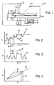
- Fig. 1 is a block diagram of a laser-spirometer combined system showing a laser producing a chest displacement signal and spirometer producing a lung volume signal for respiration measurement and a patient positioned to radiation therapy treatment;
- Fig. 2 is a graph of a typical spirometer lung volume signal during both regular breathing and a breath-hold showing drift in the signal;
- Fig. 3 is a graph of a typical laser chest displacement signal showing a chest contraction at the beginning of a breath-hold
- Fig. 4 is a graph of the lung volume signal versus the chest displacement signal showing their correlation and hysteresis
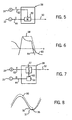
- Fig. 5 is a block diagram of the processing of the lung volume signal and chest displacement signal of Fig. 1 to modify the chest displacement signal to produce a corrected respiration signal;
- Fig. 6 shows a breath-hold detection system that may be used with the processing of Fig. 5 to further correct the chest displacement signal;
- Fig. 7 is a block diagram similar to Fig. 5 of the processing of the lung volume signal and chest displacement signal of Fig. 1 to modify the lung volume signal to produce a corrected respiration signal;
- Fig. 8 is a plot of the lung volume signal of Fig. 7 as corrected to produce the corrected respiration signal
- Fig. 9 is a block diagram of a visual feedback system that may be used in the system of Fig. 1 providing a corrected respiration signal and a breathing pattern signal to the patient;
- Fig. 10 is a simplified representation of the display of the visual feedback system of Fig. 9 ;
- Fig. 11 is a flow chart of the steps employed in the present invention to generate a treatment plan for the system of Fig. 1 that is corrected for lung motion;
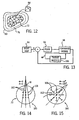
- Fig. 12 is a cross-section through a lung of a patient during three stages of the breathing cycle showing generation of a solid model in the lung at a full expiration stage of breathing;
- Fig. 13 is a block diagram of the treatment planning system used with intensity modulated radiation therapy and suitable for use with the present invention
- Figs. 14 and 15 show one method of modification of the dose calculation used in the treatment planning system of Fig. 13 to accommodate lung expansion by modeling curved radiation beams;
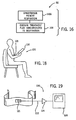
- Fig. 16 is a flow chart of the radiation therapy process using the treatment plan generated according to the present invention and breathing control using the corrected respiration signal of the present invention
- Fig. 17 is a diagram of the motion of the radiation source of the system of claim 1 showing synchronization of the patient's breathing with the standard breathing pattern of the treatment plan;
- Fig. 18 is a diagram showing a patient using a training system per the present invention.
- Fig. 19 is a block diagram of the components of the training system of Fig. 18 .
- an intensity modulated radiation therapy (IMRT) system 10 suitable for use with the present invention provides a radiation source 12.
- the radiation source 12 is a fan beam and may orbit around a patient 14 in a rotational plane parallel to the plane of the fan beam and perpendicular to the plane of the figure transmitting a multi-beamlet radiation beam 16 through the patient 14 to be received by a detector device 18 and/or a radiation stop.
- the radiation source 12 may be supported for such rotation on a gantry (not shown).
- the radiation source is a cone beam also positionable about the patient 14, typically to a few selected angles (6-10).
- the fan or cone beams are intensity modulated to achieve the best dose distribution according to a physician's prescription.
- the system shown is also representative of a tomographic imaging system in which case the radiation source 12 is not modulated and the detector device collects projection images to be mathematically combined in a tomographic image according to methods well known in the art.
- the patient 14 may be supported in a supine position on a table 20 and the patient's respiration monitored using conventional respiration monitoring such as a chest cuff, displacement sensor, or spirometer.
- the patient's respiration is monitored with an improved respiration monitor.
- the patient is positioned so that a laser displacement sensor 22 (or other displacement sensors) may monitor respiratory motion of the patient's chest.
- the patient 14 breathes through a spirometer 24 measuring airflow into and out of the patient's lungs and the patient may wear video glasses 26 to provide for feedback with respect to the patient's breathing as will be described.
- the signal from the spirometer 24 may be preprocessed by an integrator 27 to provide a lung volume signal to a controlling computer 28 which may alternatively receive the signal from the spirometer 24 directly and implement the integrator 27 internally.
- the computer 28 also receives a displacement signal from the laser displacement sensor 22 and may communicate with a control terminal 30 such as may include a video screen, keyboard, and mouse or the like.
- the computer 28 may further control delivery of radiation from the radiation source 12 about the patient 14 and the intensity of the beamlets of the beam 16 by shutters or moving leaves according to methods well known in the art In the case of an imaging system, the computer may collect the projections and perform a tomographic reconstruction.
- a typical lung volume signal 32 derived from spirometer 24 shows peaks 34 and troughs 36 corresponding, respectively, to full inspiration and full expiration by the patient 14 during a regular breathing period 38.
- the present invention contemplates treatment of the patient 14 without the need for breath-holding, however, the respiration signal developed for the present invention may also find use with breath-hold protocols and therefore, the lung volume signal 32 during breath-hold is also shown.
- a plateau 40 is created in the lung volume signal 32 reflecting constant lung volume during this breath-hold period 41.
- the integration of the output of the spirometer 24 to convert its flow signal (volume/time as a function of time) into a lung volume signal (volume as a function of time) may result in drift, as shown generally by the dotted trend line 42, caused by the integration over time of small offsets in the spirometer signal.
- drift can be confusing to a patient 14 who is attempting to match his or her breathing, as indicated by this drifting signal, to a standard breathing guiding pattern which does not drift.
- drift is largely absent from the laser chest displacement signal 44 which does not employ the integrator required of the spirometer 24 but measures chest displacement directly.
- the breathing period 38 of the laser chest displacement signal 44 will match the breathing period 38 of the spirometer lung volume signal 32, but the laser chest displacement signal 44 provides a displacement output rather than an output of lung volume.
- Signal amplitude range variations due to daily setup variations cause deviations between lung volume and chest displacement
- the laser chest displacement signal 44 decays because of muscle relaxation despite the lack of change in lung volume.
- correlation curve 46 plots the lung volume signal 32 on the vertical axis against chest displacement signal 44 on the horizontal axis for one breathing period 38.
- the points of the correlation curve 46 may be fit to a slope line 48 by a least square fit or other techniques wherein the slope of the slope line 48 provides the correlation between the lung volume signal 32 and the chest displacement signal 44.
- the correlation curve 46 will have some hysteresis meaning that the functional relationship between lung volume and chest displacement as displacement increases is different from the functional relationship between the lung volume and the chest displacement as displacement decreases.
- the correlation failure between lung volume signal 32 and the chest displacement signal 44 during a breath-hold of breath-hold period 41 is shown by a short flat are a in the correlation curve 46.
- correlation curve 46 will generally rise or fall over time preserving approximately the same shape and slope line 48.
- a corrected respiration signal 50 may be obtained by using both the lung volume signal 32 and the chest displacement signal 44 to provide a corrected respiration signal 50 that is both relatively free from drift, calibrated in units of volume, and free from breath-hold artifacts.
- This correction process may be implemented by model 52 realized preferably as a program running in computer 28.
- the model 52 receives the lung volume signal 32 and the chest displacement signal 44 to deduce the slope of the slope line 48.
- the chest displacement signal 44 is then scaled by the slope to translate the chest displacement into units of lung volume but without drift as the corrected respiration signal 50.
- the model 52 may provide for breath-hold-detection to hold corrected respiration signal 50 constant when a breath-hold is detected.
- the breath-hold detection may monitor the laser chest displacement signal 44.
- Breath-hold cam be detected from the shape of the chest displacement signal 44 in which the derivative of this signal changes abruptly at the beginning and ending of breath-hold or from spirometer signal 60 in which the flow reading is zero during breath-hold.
- the corrected respiration signal 50 is held to a constant value 58 until the breath-hold is over.
- Such a system may be used to eliminate the decay artifact of the laser chest displacement signal 44 during the breath-hold period 41.
- the correlation curve 46 may be captured as a lookup table fitted to a nonlinear equation and used to map arguments of the chest displacement signal 44 to values of lung volume according to the function captured by the correlation curve 46.
- a model 52 that accommodates hysteresis can be obtained.
- the use of correlation curve 46 to convert the chest displacement signal 44 into values of lung volume effectively eliminates the decay artifact in the chest displacement signal 44 because the flat portion of the correlation curve 46 during breath-hold period 41 holds lung volume output constant during the breath-hold period 41.
- the correlation curve 46 may be an average of a number of breathing periods 38 after baseline correction.
- the lung volume signal 32 from the spirometer 24 and the chest displacement signal 44 from the laser displacement sensor 22 may also be used to correct the lung volume signal 32 to be the corrected respiration signal 50.
- the integrator 27 is preferably implemented within the computer 28 so that the integration constant can be controlled directly.
- a correction value is provided by constant generator 64 at a regular period at a given phase in the respiration cycle as determined by the laser displacement sensor (as shown) or the spirometer 24.
- the correction value is preferably a stored sample of the lung volume signal 32 at the given phase from an early time in the monitoring of respiration when the spirometer signal baseline drift is negligible.
- the spirometer lung volume signal 32 is recorded as reference reading 31.
- the chest displacement signal 44 (not shown) may also be recorded to identify the given phase of the breathing cycle.
- the corrected respiration signal 50 is set back to the reference reading 31. In this way, spirometer signal drift is corrected for every cycle and is thereby very small.
- the corrected respiration signal 50 may be displayed to the patient 14 via the glasses 26 together with a pre-established standard breathing guiding pattern 66 preferably obtained from measurements both of the amplitude and periodicity of the patient's ordinary respiration.
- the standard breathing guiding pattern 66 may be measured from the patient 14 using the techniques described above and the corrected respiration signals 50 during that measurement stored in computer memory.
- the display 68 of the glasses 26 may show to the patient a full cycle of the standard breathing guiding pattern 66 and a repeatedly drawn corrected respiration signal 50 updated in real time with the horizontal axis scrolling from left to right.
- the patient 14, observing the corrected respiration signal 50 for his or her current breathing, and the standard breathing guiding pattern 66, may be instructed to conform their breathing to the standard breathing guiding pattern 66.
- This ability to synchronize the patient's breathing with a stored pattern makes possible the preparation of a treatment plan that is keyed to the standard breathing guiding pattern 66 and which may thus compensate for movement of a tumor in the lung or closely adjacent thereto.
- the spirometer laser correction system of the present invention may also provide advantages when used in conventional breath-hold situations.
- the chest displacement signal 44 need not be a laser sensor, but other chest displacement methods including other optical techniques, cuffs, and mechanical transducers may be used.
- Imaging modalities including x-ray tomography and magnetic resonance imaging create images using a set of measurements acquired over a considerable length of time during which regular physiological motion such as breathing may occur. These measurements which may be x-ray projections or resonance signals acquired with a given set of magnetic gradients are mathematically combined to produce an image. Changes in the position of the tissue during this acquisition process may cause artifacts in the reconstructed images.
- the present invention may be used to provide a robust respiration signal that may be used to time or order acquisitions according to known techniques to minimize or eliminate these artifacts.
- a treatment plan can be developed for controlling the intensity of the various rays of the radiation source 12 to treat tumor tissue on or near the patient's lungs or other organ having predictable motion.
- the treatment plan will be provided by the computer 28 which will coordinate operation of the radiation source 12 according to a respiration signal so as to treat the patient 14 during movement of the tumor.
- the patient 14 may observe a predetermined breathing guiding pattern through the glasses 26 to synchronize his or her breathing to a breathing guiding pattern used in preparation of the treatment plan.
- CT images are acquired at multiple phases of the patient's normal breathing cycle. This can be achieved by instructing the patient to hold his or her breath at different breathing phases or by using a dynamic CT scan, a commercially available scanning protocol.
- the dynamic CT scan collects multiple CT images at different phases while a patient breathes normally during scanning.
- these multiple CT images are used to develop three dimensional displacement maps at different breathing phases. These displacement maps show displacement of the tissue from a base state (at a given respiration phase, preferably full expiration) and can be obtained by solid modeling or image registration methods.
- a lung surface 72 is extracted from the CT image of the lung at expiration using image segmentation and surface reconstruction techniques well known in the art. This surface is used to generate a solid finite element model.
- the solid model is filled with tetrahedral elements 84 with nodes along the middle of each side of the tetrahedron.
- the surfaces of lung 76 and 80 at other phases are then extracted to form target surfaces whose shape defines the space that the solid lung model can expand.
- the model of the lung surface 72 at full expiration may be loaded with a negative surface pressure so that it expands following the normal physics of a solid material composed of a uniform isotropic substance assuming frictionless contact between the lung and the thoracic wall. It is believed that such a modeling is appropriate for normal quiet breathing.
- the lung model expands until the space between the lung model and target surface of the lung at the next phase of respiration is closed.
- a displacement map between the two phases is then obtained by calculating the corresponding nodal position difference before and after deformation. This process is repeated on the lung surfaces at other breathing phases that CT images are acquired. Displacement maps of any other breathing phases can be interpolated from the results of the two closest phases.
- Image set 100 having multiple images at different breathing phases are then created, as indicated by block 78, by using the corresponding displacement map and 3D image warping.
- the images of the image set 100 are preferably a registered respiration cycle angle determined from the corrected respiration signal 50 described above but may alternatively be registered to the lung volume signal 32 alone, the chest displacement signal 44 alone, or a breathing signal based on an internal marker position calculated from the internal marker position in the solid model. A time series of images that simulates patient's breathing is thereby created.
- a dose map 94 (shown in Fig. 13 ) indicating a desired radiation dose at different positions within the patient with respect to the images for the expiration lung is created using tools and techniques known in the art.
- beamlet dose distributions are calculated by using the images of the image set 100 at corresponding breathing phase per process block 90.
- This treatment plan may then be applied to the patient per process block 92.
- a treatment plan defines the intensity of multiple rays of the radiation beam 16 for different angles of the radiation source 12 about the patient. The intensities are selected so that the beams at the different angles add with high total intensity on the tumor and add with low intensity on non-tumor tissue.
- a desired tissue dose map 94 is created, for example, as zones superimposed on the image of the expiration lung, each zone mapping desired doses for different elements or node points of the image of the expiration lung.
- the process of determining a treatment plan 96 from a dose map 94 is extremely complex because of the interaction of the multiple rays at different angles. Accordingly, it is common to use an iterative process in which a treatment plan 96 is iteratively adjusted according to one of a number of algorithms, for example, simulated annealing. At each stage of the adjustment, the dose that would result from the treatment plan 96 is modeled per forward model 98. This dose predicted by the forward model 98 is then compared to the desired dose map 94 and the error is used to further adjustment of the treatment plan 96.
- the present invention may be integrated into such iterative systems by simply modifying of the forward model 98 to reflect anticipated changes in the lung during the treatment process as captured by the image set 100.
- this may be accomplished by assuming that there is a fixed relationship between the angle of the radiation beam 16 and the phase of the breathing cycle.
- the dose is calculated on a different image of the image set 100 depending on the angle of the radiation beam 16 being considered.
- the forward model 98 may incorporate the expansion of the lung as a function of angle of the beam 16 in a number of ways.
- the expansion of the lungs is accommodated by modeling the normally straight beamlets 102 of beam 16 as curved beamlets 102' that follow local tissue dislocations when the lung is expanded.
- the beamlets 102 of the radiation beam 16 will be modeled in dose map 94 as straight lines through the tissue of image of the expiration lung.
- a curved beamlet 102 is used by the dose map 94 based on an expanded image of the image set 100.
- the curved beamlet 102 allows correct dose placement to be accumulated on the image associated with full expiration by remapping expansion of the tissue to curvature of the beamlet 102.
- the beamlet 102 curves inward toward the center reflecting the fact that the tissue has in fact expanded relative to the image of the expiration lung used for tallying the total dose.
- the treatment plan 96 so generated will differ from a normal treatment plan by describing the intensity of each ray as a function not only of delivery phase but also as a function of respiration cycle angle R.
- the breathing of the patient must be synchronized with the delivery phase ⁇ and the assumed respiration cycle angle R of the treatment plan 96.
- the radiation source 12 produces a radiation beam 16 comprised of a variety of different rays, each identified from an angle from the center of the beam of ⁇ .
- the treatment plan 96 will include intensity values 116 for each of the rays 118 related to given gantry angles 120 and respiratory cycle angles 122.
- the mapping of respiration phase 122 to rotational gantry angle 120 will be selected to accommodate the physical constraints of the radiation therapy system 10 in applying radiation and may include a 1:1 mapping in which one 360 degree rotation of the radiation source 12 corresponds to a single breath cycle (360 degrees) or more typically, multiple breath cycles per each rotation of the gantry.
- the treatment plan 96 must be derived differently because the relationship between delivery phase and breathing phase cannot be as accurately controlled because of mechanical limitations to leaf movement speeds. For this reason, the optimization process must include an additional level of iteration.
- This treatment plan is prepared using standard planning software for such first generation machines similar to that described with respect to Fig. 13 .
- the necessary leaf motion sequence to produce the desired beamlet intensities is then calculated by the machine's leaf motion sequence calculator to relate each beamlet intensity to a respiration phase that would exist at the time of the exposure based on movement speed of the shutter and the respiration of the patient following the standard breathing guiding pattern 66.
- the beamlets are curved, as described above, to reflect the distortion of the tissue caused by respirations.
- the dose using the beamlet intensities is then recalculated using the curved beamlets. If the dose is within a predetermined tolerance of the desired dose, the planning is complete. Otherwise, the intensities of the beamlets are adjusted using the process of Fig. 13 .
- the leaf motion sequence calculator is again used to determine actual respiration phase during the beam exposure and the beamlet curvatures are again adjusted.
- the dose using the beamlet intensities is then recalculated using the newly curved beamlets. If the dose is within a predetermined tolerance of the desired dose, the planning is complete. Otherwise this process continues to repeat until the desired dose is obtained.
- a simple modification of this embodiment may allow the delivery phase ( ⁇ ) to speed up or slow down (together with the gantry in a second generation IMRT machine) to attempt to match changes in the respiration cycle angle R of the patient 14 as indicated by corrected respiration signal 50.
- the patient may continue to breathe provided that the patient can control the relative phase of his or her breath. This procedure is much more readily tolerated than breath-hold procedures.
- a portable patient breathing training system 130 may be used to help patients reduce tracking error.
- a simple respiratory motion tracking system comprises a pressure sensor 121 detecting abdomen motion. Signals 122 from the pressure sensor 121 are digitized by analog to digital converter 124 and collected on a portable computer such as PDA 126 or the like displaying a stored breathing guiding pattern 66 per Fig. 10 as derived from the patient's normal breathing signal along with a respiration signal derived from the pressure sensor 121.
Landscapes
- Health & Medical Sciences (AREA)
- Life Sciences & Earth Sciences (AREA)
- Engineering & Computer Science (AREA)
- Biomedical Technology (AREA)
- Public Health (AREA)
- Pathology (AREA)
- Veterinary Medicine (AREA)
- Medical Informatics (AREA)
- General Health & Medical Sciences (AREA)
- Animal Behavior & Ethology (AREA)
- Surgery (AREA)
- Nuclear Medicine, Radiotherapy & Molecular Imaging (AREA)
- Physics & Mathematics (AREA)
- Heart & Thoracic Surgery (AREA)
- Molecular Biology (AREA)
- Biophysics (AREA)
- Physiology (AREA)
- Radiology & Medical Imaging (AREA)
- Optics & Photonics (AREA)
- High Energy & Nuclear Physics (AREA)
- Dentistry (AREA)
- Oral & Maxillofacial Surgery (AREA)
- Radiation-Therapy Devices (AREA)
- Measurement Of Radiation (AREA)
- Photometry And Measurement Of Optical Pulse Characteristics (AREA)
Claims (24)
- Atmungsmonitor, umfassend:ein Spirometer (24), das dazu ausgebildet ist, einen Luftstrom von der Lunge eines Patienten mit Atmung zu empfangen, um ein Luftstromsignal (60) bereitzustellen; undeinen Brustkorbhebungssensor (22), der dazu ausgebildet ist, die Hebung des Brustkorbes des Patienten mit Atmung zu überwachen, um ein Brustkorbhebungssignal (44) bereitzustellen;wobei der Atmungsmonitor des Weiteren einen Kalibrierungsschaltkreis umfasst, der das Luftstromsignal (60) und das Brustkorbhebungssignal (44) empfängt, um ein korrigiertes Atmungssignal (50) bereitzustellen, das Informationen sowohl vom Luftstromsignal (60) wie auch vom Brustkorbhebungssignal (44) kombiniert;dadurch gekennzeichnet, dass der Kalibrierungsschaltkreis Folgendes enthält:einen Integrator (27), der das Luftstromsignal (60) empfängt, um ein Lungenvolumensignal (32) zu erzeugen; undeinen Grundlinienkorrektor, der das Lungenvolumensignal (32) und das Brustkorbhebungssignal (44) empfängt, um einen Integrationsversatz des Lungenvolumensignals (32) zu korrigieren, um das korrigierte Atmungssignal (50) auf der Basis des Brustkorbhebungssignals (44) zu erzeugen.
- Atmungsmonitor nach Anspruch 1, wobei die Korrektur des Integrationsversatzes periodisch bei einer vorbestimmten Atmungsphase durch Einstellen des Lungenvolumensignals (32) auf einen gespeicherten Kalibrierungswert erfolgt.
- Atmungsmonitor nach Anspruch 2, wobei der Kalibrierungswert ein früherer Wert des Lungenvolumensignals (32) bei der vorbestimmten Phase ist.
- Atmungsmonitor nach Anspruch 1, wobei der Kalibrierungsschaltkreis ein Modell (52) des Verhältnisses zwischen Lungenvolumen- und Brustkorbhebungssignal (44) enthält, wobei das Modell (52) das Brustkorbhebungssignal (44) empfängt, um ein Lungenvolumensignal (32) als korrigiertes Atmungssignal (50) bereitzustellen.
- Atmungsmonitor nach Anspruch 4, wobei das Modell (52) eine lineare Funktion ist, die das Brustkorbhebungssignal (44) auf das Lungenvolumen bezieht.
- Atmungsmonitor nach Anspruch 5, wobei das Modell (52) ein Multiplizierer ist, der das Brustkorbhebungssignal (44) mit einem Faktor multipliziert, der aus einer Korrelation zwischen dem Lungenvolumensignal (32) und dem Brustkorbhebungssignal (44) bestimmt wird, um das korrigierte Atmungssignal (50) zu erzeugen.
- Atmungsmonitor nach Anspruch 4, wobei das Modell (52) eine nicht-lineare Funktion ist, die das Brustkorbhebungssignal (44) auf das Lungenvolumen bezieht..
- Atmungsmonitor nach Anspruch 7, wobei das Modell (52) eine Verweistabelle ist, in der das Verhältnis zwischen Lungenvolumen und Brustkorbhebung für mindestens einen Atmungszyklus aufgezeichnet ist, wobei die Verweistabelle das Brustkorbhebungssignal (44) empfängt, um das korrigierte Atmungssignal (50) auszugeben.
- Atmungsmonitor nach Anspruch 4, wobei das Modell (52) ein unterschiedliches Verhältnis zwischen dem Brustkorbhebungssignal (44) und dem Lungenvolumen während des Einatmens und Ausatmens bereitstellt.
- Atmungsmonitor nach Anspruch 4, wobei das Modell (52) ein Luftanhalten (41) aus dem Brustkorbhebungssignal (44) erfasst und das korrigierte Atmungssignal (50) bis zum Ende des Luftanhaltens konstant hält.
- Atmungsmonitor nach Anspruch 1, des Weiteren umfassend eine Patientenanzeige (68), die dem Patienten (14) das korrigierte Atmungssignal (50) anzeigt.
- Strahlungstherapiesystem (10), umfassend:den Atmungsmonitor nach Anspruch 1 und eine steuerbare Strahlungsquelle (12) zum Empfangen des korrigierten Atmungssignals (50), um eine Strahlung, die an einen Patienten (14) abgegeben wird, entsprechend dem korrigierten Atmungssignal (50) zu steuern.
- System zur Erzeugung medizinischer Bilder (10), umfassend:den Atmungsmonitor nach Anspruch 1 und einen Bildgeber zum Empfangen des korrigierten Atmungssignals (50) und zum Erfassen von Bildkomponentensignalen von einem Patienten (14) über verschiedene Atmungsphasen (122), und zum mathematischen Kombinieren der Bildkomponentensignale entsprechend den Atmungsphasen, wenn die Bildkomponentensignale zum Erzeugen eines zusammengesetzten Bildes (80, 100) erfasst wurden.
- Verfahren zum Erzeugen eines korrigierten Atmungssignals (50), wobei das Verfahren die folgenden Schritte umfasst:(a) Überwachen der Atmung eines Patienten mit einem Spirometer (24), das dazu ausgebildet ist, einen Luftstrom von der Lunge eines Patienten zu empfangen, um ein Luftstromsignal (60) bereitzustellen; und(b) Überwachen der Atmung eines Patienten mit einem Brustkorbhebungssensor (22), der dazu ausgebildet ist, die Hebung des Brustkorbes des Patienten mit Atmung zu überwachen, um ein Brustkorbhebungssignal (44) bereitzustellen;(c) Kombinieren des Luftstromsignals (60) und des Brustkorbhebungssignals (44), um ein korrigiertes Atmungssignal (50) bereitzustellen;
dadurch gekennzeichnet, dass das Verfahren des Weiteren die folgenden Schritte umfasst:(d) Integrieren des Luftstromsignals (60), um ein Lungenvolumensignal (32) zu erzeugen; und(e) Verwenden des Brustkorbhebungssignals (44) zur Korrektur eines Integrationsversatzes des Lungenvolumensignals (32), um das korrigierte Atmungssignal (50) zu erzeugen. - Verfahren nach Anspruch 14, wobei die Korrektur des Integrationsversatzes periodisch bei einer vorbestimmten Atmungsphase durch Einstellen des Lungenvolumensignals (32) auf einen gespeicherten Kalibrierungswert erfolgt.
- Verfahren nach Anspruch 15, wobei der gespeicherte Kalibrierungswert ein früherer Wert des Lungenvolumensignals (32) bei der vorbestimmten Atmungsphase ist.
- Verfahren nach Anspruch 14, wobei das Lungenvolumensignal (32) bei einem Modell (52) des Verhältnisses zwischen Lungenvolumen- und Brustkorbhebungssignal angewendet wird, um ein Lungenvolumensignal (32) als korrigiertes Atmungssignal (50) bereitzustellen.
- Verfahren nach Anspruch 17, wobei das Modell (52) eine lineare Funktion ist, die das Brustkorbhebungssignal auf das Lungenvolumen bezieht.
- Verfahren nach Anspruch 17, wobei das Modell (52) ein Multiplizierer ist, der das Brustkorbhebungssignal (44) mit einem Faktor multipliziert, der aus einer Korrelation zwischen dem Lungenvolumensignal (32) und dem Brustkorbhebungssignal (44) bestimmt wird, um das korrigierte Atmungssignal (50) zu erzeugen.
- Verfahren nach Anspruch 17, wobei das Modell (52) eine nicht-lineare Funktion ist, die das Brustkorbhebungssignal (44) auf das Lungenvolumen bezieht.
- Verfahren nach Anspruch 20, wobei das Modell (52) eine Verweistabelle ist, in der das Verhältnis zwischen Lungenvolumen und Brustkorbhebung für mindestens einen Atmungszyklus aufgezeichnet ist, wobei die Verweistabelle das Brustkorbhebungssignal (44) empfängt, um das korrigierte Atmungssignal (50) auszugeben.
- Verfahren nach Anspruch 14, wobei das Modell (52) ein unterschiedliches funktionelles Verhältnis zwischen dem Brustkorbhebungssignal (44) und dem Lungenvolumen während des Einatmens und Ausatmens bereitstellt.
- Verfahren nach Anspruch 14, wobei das Modell (52) ein Luftanhalten (41) aus dem Brustkorbhebungssignal (44) erfasst und das korrigierte Atmungssignal (50) bis zum Ende des Luftanhaltens (41) konstant hält.
- Verfahren zur Erzeugung eines medizinischen Bildes, umfassend:das Verfahren nach Anspruch 14;Erfassen von Bildkomponentensignalen von einem Patienten (14) über verschiedene Atmungsphasen; undmathematisches Kombinieren der Bildkomponentensignale entsprechend Atmungsphasen, sobald die Bildkomponentensignale zur Erzeugung eines zusammengesetzten Bildes (80, 100) erfasst sind.
Applications Claiming Priority (3)
| Application Number | Priority Date | Filing Date | Title |
|---|---|---|---|
| US47858403P | 2003-06-13 | 2003-06-13 | |
| US10/715,986 US7367955B2 (en) | 2003-06-13 | 2003-11-18 | Combined laser spirometer motion tracking system for radiotherapy |
| PCT/US2004/018890 WO2004112607A1 (en) | 2003-06-13 | 2004-06-10 | A combined laser spirometer motion tracking system for radiotherapy |
Publications (2)
| Publication Number | Publication Date |
|---|---|
| EP1633246A1 EP1633246A1 (de) | 2006-03-15 |
| EP1633246B1 true EP1633246B1 (de) | 2008-11-26 |
Family
ID=33514257
Family Applications (1)
| Application Number | Title | Priority Date | Filing Date |
|---|---|---|---|
| EP04755204A Expired - Lifetime EP1633246B1 (de) | 2003-06-13 | 2004-06-10 | Kombiniertes laser-spirometer system für die strahlentherapie |
Country Status (5)
| Country | Link |
|---|---|
| US (1) | US7367955B2 (de) |
| EP (1) | EP1633246B1 (de) |
| AT (1) | ATE415125T1 (de) |
| DE (1) | DE602004017990D1 (de) |
| WO (1) | WO2004112607A1 (de) |
Families Citing this family (148)
| Publication number | Priority date | Publication date | Assignee | Title |
|---|---|---|---|---|
| US5915380A (en) | 1997-03-14 | 1999-06-29 | Nellcor Puritan Bennett Incorporated | System and method for controlling the start up of a patient ventilator |
| US20050016530A1 (en) * | 2003-07-09 | 2005-01-27 | Mccutcheon John | Treatment planning with implantable bronchial isolation devices |
| US8989349B2 (en) * | 2004-09-30 | 2015-03-24 | Accuray, Inc. | Dynamic tracking of moving targets |
| US8027715B2 (en) * | 2004-10-02 | 2011-09-27 | Accuray Incorporated | Non-linear correlation models for internal target movement |
| US7957507B2 (en) | 2005-02-28 | 2011-06-07 | Cadman Patrick F | Method and apparatus for modulating a radiation beam |
| US20090048500A1 (en) * | 2005-04-20 | 2009-02-19 | Respimetrix, Inc. | Method for using a non-invasive cardiac and respiratory monitoring system |
| US8232535B2 (en) | 2005-05-10 | 2012-07-31 | Tomotherapy Incorporated | System and method of treating a patient with radiation therapy |
| CA2616306A1 (en) | 2005-07-22 | 2007-02-01 | Tomotherapy Incorporated | Method and system for processing data relating to a radiation therapy treatment plan |
| CN101268467B (zh) | 2005-07-22 | 2012-07-18 | 断层放疗公司 | 用于评估治疗计划的实施中的质量保证标准的方法和系统 |
| CA2616301A1 (en) * | 2005-07-22 | 2007-02-01 | Tomotherapy Incorporated | Method and system for evaluating delivered dose |
| JP2009514559A (ja) | 2005-07-22 | 2009-04-09 | トモセラピー・インコーポレーテッド | 線量体積ヒストグラムを用いて輪郭構造を生成するシステムおよび方法 |
| EP1906827A4 (de) | 2005-07-22 | 2009-10-21 | Tomotherapy Inc | System und verfahren zur evaluierung der mittels eines strahlungstherapiesystems verabreichten dosis |
| AU2006272742A1 (en) | 2005-07-22 | 2007-02-01 | Tomotherapy Incorporated | System and method of delivering radiation therapy to a moving region of interest |
| US7639853B2 (en) | 2005-07-22 | 2009-12-29 | Tomotherapy Incorporated | Method of and system for predicting dose delivery |
| US8442287B2 (en) | 2005-07-22 | 2013-05-14 | Tomotherapy Incorporated | Method and system for evaluating quality assurance criteria in delivery of a treatment plan |
| US7567694B2 (en) | 2005-07-22 | 2009-07-28 | Tomotherapy Incorporated | Method of placing constraints on a deformation map and system for implementing same |
| EP1907065B1 (de) | 2005-07-22 | 2012-11-07 | TomoTherapy, Inc. | Verfahren und system zur anpassung eines strahlentherapiebehandlungsplans auf der grundlage eines biologischen modells |
| JP5060476B2 (ja) * | 2005-07-22 | 2012-10-31 | トモセラピー・インコーポレーテッド | 放射線療法を受けている患者の呼吸位相を検出するシステムおよび方法 |
| EP3175886B1 (de) | 2005-07-23 | 2018-06-27 | TomoTherapy, Inc. | Strahlungstherapiebildgebung und abgabe mittels koordinierter bewegung von gantry und liege |
| US7678063B2 (en) * | 2006-01-06 | 2010-03-16 | Mayo Foundation For Medical Education And Research | Motion monitor system for use with imaging systems |
| JP2007236760A (ja) * | 2006-03-10 | 2007-09-20 | Mitsubishi Heavy Ind Ltd | 放射線治療装置制御装置および放射線照射方法 |
| US8021310B2 (en) | 2006-04-21 | 2011-09-20 | Nellcor Puritan Bennett Llc | Work of breathing display for a ventilation system |
| DE502006001840D1 (de) * | 2006-06-22 | 2008-11-27 | Siemens Schweiz Ag | Vorrichtung zur räumlichen Verfolgung einer beweglichen Lage eines Köperteils |
| US7784461B2 (en) | 2006-09-26 | 2010-08-31 | Nellcor Puritan Bennett Llc | Three-dimensional waveform display for a breathing assistance system |
| US8971992B2 (en) * | 2007-05-07 | 2015-03-03 | Kabushiki Kaisha Toshiba | Magnetic resonance imaging apparatus and control method thereof |
| US7575554B2 (en) * | 2007-09-21 | 2009-08-18 | University Of Yamanashi | Breathing monitoring device having a multi-point detector |
| US8222616B2 (en) | 2007-10-25 | 2012-07-17 | Tomotherapy Incorporated | Method for adapting fractionation of a radiation therapy dose |
| US9248312B2 (en) | 2007-10-26 | 2016-02-02 | Accuray Incorporated | Automatic correlation modeling of an internal target |
| US8064642B2 (en) * | 2008-01-10 | 2011-11-22 | Accuray Incorporated | Constrained-curve correlation model |
| WO2009111580A2 (en) * | 2008-03-04 | 2009-09-11 | Tomotherapy Incorporated | Method and system for improved image segmentation |
| US8017915B2 (en) * | 2008-03-14 | 2011-09-13 | Reflexion Medical, Inc. | Method and apparatus for emission guided radiation therapy |
| US8368038B2 (en) | 2008-05-22 | 2013-02-05 | Vladimir Balakin | Method and apparatus for intensity control of a charged particle beam extracted from a synchrotron |
| US10092776B2 (en) | 2008-05-22 | 2018-10-09 | Susan L. Michaud | Integrated translation/rotation charged particle imaging/treatment apparatus and method of use thereof |
| US9579525B2 (en) | 2008-05-22 | 2017-02-28 | Vladimir Balakin | Multi-axis charged particle cancer therapy method and apparatus |
| US8374314B2 (en) | 2008-05-22 | 2013-02-12 | Vladimir Balakin | Synchronized X-ray / breathing method and apparatus used in conjunction with a charged particle cancer therapy system |
| US9737733B2 (en) | 2008-05-22 | 2017-08-22 | W. Davis Lee | Charged particle state determination apparatus and method of use thereof |
| US8598543B2 (en) | 2008-05-22 | 2013-12-03 | Vladimir Balakin | Multi-axis/multi-field charged particle cancer therapy method and apparatus |
| US8519365B2 (en) | 2008-05-22 | 2013-08-27 | Vladimir Balakin | Charged particle cancer therapy imaging method and apparatus |
| US9737272B2 (en) | 2008-05-22 | 2017-08-22 | W. Davis Lee | Charged particle cancer therapy beam state determination apparatus and method of use thereof |
| US9782140B2 (en) | 2008-05-22 | 2017-10-10 | Susan L. Michaud | Hybrid charged particle / X-ray-imaging / treatment apparatus and method of use thereof |
| US8089054B2 (en) | 2008-05-22 | 2012-01-03 | Vladimir Balakin | Charged particle beam acceleration and extraction method and apparatus used in conjunction with a charged particle cancer therapy system |
| US9044600B2 (en) | 2008-05-22 | 2015-06-02 | Vladimir Balakin | Proton tomography apparatus and method of operation therefor |
| US9981147B2 (en) | 2008-05-22 | 2018-05-29 | W. Davis Lee | Ion beam extraction apparatus and method of use thereof |
| US9616252B2 (en) | 2008-05-22 | 2017-04-11 | Vladimir Balakin | Multi-field cancer therapy apparatus and method of use thereof |
| US9056199B2 (en) | 2008-05-22 | 2015-06-16 | Vladimir Balakin | Charged particle treatment, rapid patient positioning apparatus and method of use thereof |
| US8710462B2 (en) | 2008-05-22 | 2014-04-29 | Vladimir Balakin | Charged particle cancer therapy beam path control method and apparatus |
| US9177751B2 (en) | 2008-05-22 | 2015-11-03 | Vladimir Balakin | Carbon ion beam injector apparatus and method of use thereof |
| US8178859B2 (en) | 2008-05-22 | 2012-05-15 | Vladimir Balakin | Proton beam positioning verification method and apparatus used in conjunction with a charged particle cancer therapy system |
| US9974978B2 (en) | 2008-05-22 | 2018-05-22 | W. Davis Lee | Scintillation array apparatus and method of use thereof |
| US8569717B2 (en) | 2008-05-22 | 2013-10-29 | Vladimir Balakin | Intensity modulated three-dimensional radiation scanning method and apparatus |
| US8975600B2 (en) | 2008-05-22 | 2015-03-10 | Vladimir Balakin | Treatment delivery control system and method of operation thereof |
| US8288742B2 (en) * | 2008-05-22 | 2012-10-16 | Vladimir Balakin | Charged particle cancer therapy patient positioning method and apparatus |
| US8637833B2 (en) | 2008-05-22 | 2014-01-28 | Vladimir Balakin | Synchrotron power supply apparatus and method of use thereof |
| US8373146B2 (en) | 2008-05-22 | 2013-02-12 | Vladimir Balakin | RF accelerator method and apparatus used in conjunction with a charged particle cancer therapy system |
| US9095040B2 (en) | 2008-05-22 | 2015-07-28 | Vladimir Balakin | Charged particle beam acceleration and extraction method and apparatus used in conjunction with a charged particle cancer therapy system |
| US10143854B2 (en) | 2008-05-22 | 2018-12-04 | Susan L. Michaud | Dual rotation charged particle imaging / treatment apparatus and method of use thereof |
| US9744380B2 (en) | 2008-05-22 | 2017-08-29 | Susan L. Michaud | Patient specific beam control assembly of a cancer therapy apparatus and method of use thereof |
| US9937362B2 (en) | 2008-05-22 | 2018-04-10 | W. Davis Lee | Dynamic energy control of a charged particle imaging/treatment apparatus and method of use thereof |
| US10684380B2 (en) | 2008-05-22 | 2020-06-16 | W. Davis Lee | Multiple scintillation detector array imaging apparatus and method of use thereof |
| US8624528B2 (en) | 2008-05-22 | 2014-01-07 | Vladimir Balakin | Method and apparatus coordinating synchrotron acceleration periods with patient respiration periods |
| US8373143B2 (en) | 2008-05-22 | 2013-02-12 | Vladimir Balakin | Patient immobilization and repositioning method and apparatus used in conjunction with charged particle cancer therapy |
| US9682254B2 (en) | 2008-05-22 | 2017-06-20 | Vladimir Balakin | Cancer surface searing apparatus and method of use thereof |
| US8309941B2 (en) | 2008-05-22 | 2012-11-13 | Vladimir Balakin | Charged particle cancer therapy and patient breath monitoring method and apparatus |
| US8436327B2 (en) | 2008-05-22 | 2013-05-07 | Vladimir Balakin | Multi-field charged particle cancer therapy method and apparatus |
| US8373145B2 (en) | 2008-05-22 | 2013-02-12 | Vladimir Balakin | Charged particle cancer therapy system magnet control method and apparatus |
| US8969834B2 (en) | 2008-05-22 | 2015-03-03 | Vladimir Balakin | Charged particle therapy patient constraint apparatus and method of use thereof |
| US9737734B2 (en) | 2008-05-22 | 2017-08-22 | Susan L. Michaud | Charged particle translation slide control apparatus and method of use thereof |
| US9155911B1 (en) | 2008-05-22 | 2015-10-13 | Vladimir Balakin | Ion source method and apparatus used in conjunction with a charged particle cancer therapy system |
| US8378321B2 (en) | 2008-05-22 | 2013-02-19 | Vladimir Balakin | Charged particle cancer therapy and patient positioning method and apparatus |
| US9910166B2 (en) | 2008-05-22 | 2018-03-06 | Stephen L. Spotts | Redundant charged particle state determination apparatus and method of use thereof |
| US7939809B2 (en) | 2008-05-22 | 2011-05-10 | Vladimir Balakin | Charged particle beam extraction method and apparatus used in conjunction with a charged particle cancer therapy system |
| US8642978B2 (en) | 2008-05-22 | 2014-02-04 | Vladimir Balakin | Charged particle cancer therapy dose distribution method and apparatus |
| US10070831B2 (en) | 2008-05-22 | 2018-09-11 | James P. Bennett | Integrated cancer therapy—imaging apparatus and method of use thereof |
| US9168392B1 (en) | 2008-05-22 | 2015-10-27 | Vladimir Balakin | Charged particle cancer therapy system X-ray apparatus and method of use thereof |
| US8129699B2 (en) | 2008-05-22 | 2012-03-06 | Vladimir Balakin | Multi-field charged particle cancer therapy method and apparatus coordinated with patient respiration |
| US8907309B2 (en) | 2009-04-17 | 2014-12-09 | Stephen L. Spotts | Treatment delivery control system and method of operation thereof |
| US10548551B2 (en) | 2008-05-22 | 2020-02-04 | W. Davis Lee | Depth resolved scintillation detector array imaging apparatus and method of use thereof |
| US9855444B2 (en) | 2008-05-22 | 2018-01-02 | Scott Penfold | X-ray detector for proton transit detection apparatus and method of use thereof |
| US9498649B2 (en) | 2008-05-22 | 2016-11-22 | Vladimir Balakin | Charged particle cancer therapy patient constraint apparatus and method of use thereof |
| US10029122B2 (en) | 2008-05-22 | 2018-07-24 | Susan L. Michaud | Charged particle—patient motion control system apparatus and method of use thereof |
| US8718231B2 (en) | 2008-05-22 | 2014-05-06 | Vladimir Balakin | X-ray tomography method and apparatus used in conjunction with a charged particle cancer therapy system |
| US8081813B2 (en) * | 2008-05-30 | 2011-12-20 | Standard Imaging, Inc. | System for assessing radiation treatment plan segmentations |
| US8627822B2 (en) | 2008-07-14 | 2014-01-14 | Vladimir Balakin | Semi-vertical positioning method and apparatus used in conjunction with a charged particle cancer therapy system |
| US8625739B2 (en) | 2008-07-14 | 2014-01-07 | Vladimir Balakin | Charged particle cancer therapy x-ray method and apparatus |
| JP2012501230A (ja) | 2008-08-28 | 2012-01-19 | トモセラピー・インコーポレーテッド | 線量不確定度を計算するシステム及び方法 |
| US8803910B2 (en) * | 2008-08-28 | 2014-08-12 | Tomotherapy Incorporated | System and method of contouring a target area |
| US20110144517A1 (en) * | 2009-01-26 | 2011-06-16 | Miguel Angel Cervantes | Video Based Automated Detection of Respiratory Events |
| EP2403600A4 (de) * | 2009-03-03 | 2012-08-29 | Tomotherapy Inc | System und verfahren zur optimierung einer heterogenen strahlungsdosis für die verabreichung an einen patienten |
| JP2012521243A (ja) * | 2009-03-25 | 2012-09-13 | コーニンクレッカ フィリップス エレクトロニクス エヌ ヴィ | 呼吸に適合した画像処理の方法及び装置 |
| US20110092840A1 (en) * | 2009-09-23 | 2011-04-21 | Feather Sensors Llc | Intelligent air flow sensors |
| WO2011041412A2 (en) * | 2009-09-29 | 2011-04-07 | Tomotherapy Incorporated | Patient support device with low attenuation properties |
| US8401148B2 (en) * | 2009-10-30 | 2013-03-19 | Tomotherapy Incorporated | Non-voxel-based broad-beam (NVBB) algorithm for intensity modulated radiation therapy dose calculation and plan optimization |
| US9119925B2 (en) | 2009-12-04 | 2015-09-01 | Covidien Lp | Quick initiation of respiratory support via a ventilator user interface |
| US8924878B2 (en) | 2009-12-04 | 2014-12-30 | Covidien Lp | Display and access to settings on a ventilator graphical user interface |
| US8335992B2 (en) | 2009-12-04 | 2012-12-18 | Nellcor Puritan Bennett Llc | Visual indication of settings changes on a ventilator graphical user interface |
| US9262588B2 (en) | 2009-12-18 | 2016-02-16 | Covidien Lp | Display of respiratory data graphs on a ventilator graphical user interface |
| US8499252B2 (en) | 2009-12-18 | 2013-07-30 | Covidien Lp | Display of respiratory data graphs on a ventilator graphical user interface |
| US10349906B2 (en) | 2010-04-16 | 2019-07-16 | James P. Bennett | Multiplexed proton tomography imaging apparatus and method of use thereof |
| US10625097B2 (en) | 2010-04-16 | 2020-04-21 | Jillian Reno | Semi-automated cancer therapy treatment apparatus and method of use thereof |
| US10555710B2 (en) | 2010-04-16 | 2020-02-11 | James P. Bennett | Simultaneous multi-axes imaging apparatus and method of use thereof |
| US10188877B2 (en) | 2010-04-16 | 2019-01-29 | W. Davis Lee | Fiducial marker/cancer imaging and treatment apparatus and method of use thereof |
| US11648420B2 (en) | 2010-04-16 | 2023-05-16 | Vladimir Balakin | Imaging assisted integrated tomography—cancer treatment apparatus and method of use thereof |
| US10179250B2 (en) | 2010-04-16 | 2019-01-15 | Nick Ruebel | Auto-updated and implemented radiation treatment plan apparatus and method of use thereof |
| US10751551B2 (en) | 2010-04-16 | 2020-08-25 | James P. Bennett | Integrated imaging-cancer treatment apparatus and method of use thereof |
| US9737731B2 (en) | 2010-04-16 | 2017-08-22 | Vladimir Balakin | Synchrotron energy control apparatus and method of use thereof |
| US10589128B2 (en) | 2010-04-16 | 2020-03-17 | Susan L. Michaud | Treatment beam path verification in a cancer therapy apparatus and method of use thereof |
| US10556126B2 (en) | 2010-04-16 | 2020-02-11 | Mark R. Amato | Automated radiation treatment plan development apparatus and method of use thereof |
| US10086214B2 (en) | 2010-04-16 | 2018-10-02 | Vladimir Balakin | Integrated tomography—cancer treatment apparatus and method of use thereof |
| US10638988B2 (en) | 2010-04-16 | 2020-05-05 | Scott Penfold | Simultaneous/single patient position X-ray and proton imaging apparatus and method of use thereof |
| US10376717B2 (en) | 2010-04-16 | 2019-08-13 | James P. Bennett | Intervening object compensating automated radiation treatment plan development apparatus and method of use thereof |
| US10518109B2 (en) | 2010-04-16 | 2019-12-31 | Jillian Reno | Transformable charged particle beam path cancer therapy apparatus and method of use thereof |
| EP2632549A1 (de) * | 2010-10-26 | 2013-09-04 | Koninklijke Philips Electronics N.V. | Therapeutische vorrichtung, computerimplementiertes verfahren und computerprogrammprodukt zur steuerung der fokussierung von strahlung auf eine sich bewegende zielzone |
| US10598539B2 (en) * | 2010-11-23 | 2020-03-24 | Feather Sensors Llc | Method and apparatus for intelligent airflow sensors |
| US8963112B1 (en) | 2011-05-25 | 2015-02-24 | Vladimir Balakin | Charged particle cancer therapy patient positioning method and apparatus |
| WO2013111141A1 (en) * | 2012-01-29 | 2013-08-01 | Sensible Medical Innovations Ltd. | Deriving individual thoracic parameters of a subject |
| US10362967B2 (en) | 2012-07-09 | 2019-07-30 | Covidien Lp | Systems and methods for missed breath detection and indication |
| US8933651B2 (en) | 2012-11-16 | 2015-01-13 | Vladimir Balakin | Charged particle accelerator magnet apparatus and method of use thereof |
| EP2962309B1 (de) | 2013-02-26 | 2022-02-16 | Accuray, Inc. | Elektromagnetisch betätigter mehrblatt-kollimator |
| BR112015022388A2 (pt) * | 2013-03-15 | 2017-07-18 | Koninklijke Philips Nv | aparelho para determinar um sinal de volume respiratório proveniente de um indivíduo, e, método para determinar um sinal de volume respiratório proveniente de um indivíduo |
| US20140343401A1 (en) * | 2013-05-14 | 2014-11-20 | Michael Huber | Systems and methods for considering target motion in medical field |
| US9375184B2 (en) * | 2013-09-12 | 2016-06-28 | Technische Universität München | System and method for prediction of respiratory motion from 3D thoracic images |
| KR101816886B1 (ko) | 2014-10-22 | 2018-01-09 | 사회복지법인 삼성생명공익재단 | 호흡 유도 시스템 및 방법 |
| US9950129B2 (en) | 2014-10-27 | 2018-04-24 | Covidien Lp | Ventilation triggering using change-point detection |
| AT517737B1 (de) * | 2015-10-02 | 2018-07-15 | Pontemed Ag | Magnetische Stimulationsvorrichtung |
| KR102510760B1 (ko) | 2016-02-15 | 2023-03-16 | 삼성전자주식회사 | 영상처리장치, 영상처리방법 및 이를 기록한 기록매체 |
| US9907981B2 (en) | 2016-03-07 | 2018-03-06 | Susan L. Michaud | Charged particle translation slide control apparatus and method of use thereof |
| US10037863B2 (en) | 2016-05-27 | 2018-07-31 | Mark R. Amato | Continuous ion beam kinetic energy dissipater apparatus and method of use thereof |
| WO2018093849A1 (en) | 2016-11-15 | 2018-05-24 | Reflexion Medical, Inc. | Methods for radiation delivery in emission-guided radiotherapy |
| US11648418B2 (en) | 2017-06-22 | 2023-05-16 | Reflexion Medical, Inc. | Systems and methods for biological adaptive radiotherapy |
| WO2019014387A1 (en) | 2017-07-11 | 2019-01-17 | Reflexion Medical, Inc. | METHODS FOR MANAGING RETENTION FOR PET SENSOR |
| DE102017212553B4 (de) * | 2017-07-21 | 2020-02-20 | Siemens Healthcare Gmbh | Synchrone MR-Bildgebung und Strahlentherapie |
| WO2019032911A1 (en) | 2017-08-09 | 2019-02-14 | Reflexion Medical, Inc. | SYSTEMS AND METHODS FOR DEFECT DETECTION IN EMISSION-GUIDED RADIOTHERAPY |
| EP3684468B1 (de) | 2017-09-22 | 2024-03-20 | RefleXion Medical, Inc. | Systeme zur abgabe von strahlung im shuttle-modus |
| US11369806B2 (en) | 2017-11-14 | 2022-06-28 | Reflexion Medical, Inc. | Systems and methods for patient monitoring for radiotherapy |
| CN119701229A (zh) | 2018-02-13 | 2025-03-28 | 反射医疗公司 | 光束站治疗计划和放射输送方法 |
| US10650585B2 (en) | 2018-06-08 | 2020-05-12 | Data Integrity Advisors, Llc | System and method for geometrically-resolved radiographic X-ray imaging |
| FR3094889B1 (fr) * | 2019-04-12 | 2022-08-19 | Quantum Surgical | Dispositif et procédé de contrôle de la respiration d’un patient pour un robot médical |
| WO2020219071A1 (en) | 2019-04-26 | 2020-10-29 | Elekta, Inc. | A method of providing proton radiation therapy utilizing periodic motion |
| AU2019477068B2 (en) | 2019-12-04 | 2026-04-09 | Data Integrity Advisors, Llc | System and method for determining radiation parameters |
| US11672934B2 (en) | 2020-05-12 | 2023-06-13 | Covidien Lp | Remote ventilator adjustment |
| CN111568424B (zh) * | 2020-05-26 | 2023-09-26 | 江苏省肿瘤医院 | 一种用于放疗中呼吸运动信号同步的装置及其使用方法 |
| US20210369232A1 (en) * | 2020-05-29 | 2021-12-02 | University Of Pittsburgh-Of The Commonwealth System Of Higher Education | Systems and methods for evaluating respiratory function using a smartphone |
| WO2022031750A1 (en) | 2020-08-07 | 2022-02-10 | Reflexion Medical, Inc. | Multi-sensor guided radiation therapy |
| WO2022098794A1 (en) | 2020-11-04 | 2022-05-12 | Reflexion Medical, Inc. | Methods for tumor tracking |
| US20230255510A1 (en) * | 2022-02-16 | 2023-08-17 | Bruce B. Hill | Spirometer attachment |
| US12440154B2 (en) * | 2023-06-05 | 2025-10-14 | GE Precision Healthcare LLC | Coached breathing system for medical imaging |
| EP4591788B1 (de) * | 2024-01-26 | 2026-04-08 | ndd Medizintechnik AG | Anordnung mit einer vorrichtung zur messung eines gasstroms und verfahren zur überprüfung einer kalibrierung solch einer vorrichtung |
| CN119075207A (zh) * | 2024-09-29 | 2024-12-06 | 中国人民解放军陆军军医大学第一附属医院 | 一种用于肿瘤放射治疗呼吸控制定位装置 |
Family Cites Families (10)
| Publication number | Priority date | Publication date | Assignee | Title |
|---|---|---|---|---|
| GB1596298A (en) * | 1977-04-07 | 1981-08-26 | Morgan Ltd P K | Method of and apparatus for detecting or measuring changes in the cross-sectional area of a non-magnetic object |
| US4373534A (en) * | 1981-04-14 | 1983-02-15 | Respitrace Corporation | Method and apparatus for calibrating respiration monitoring system |
| US6062216A (en) * | 1996-12-27 | 2000-05-16 | Children's Medical Center Corporation | Sleep apnea detector system |
| CA2339497C (en) | 1998-08-06 | 2003-10-07 | Wisconsin Alumni Research Foundation | Delivery modification system for radiation therapy |
| US6621889B1 (en) * | 1998-10-23 | 2003-09-16 | Varian Medical Systems, Inc. | Method and system for predictive physiological gating of radiation therapy |
| US6144875A (en) | 1999-03-16 | 2000-11-07 | Accuray Incorporated | Apparatus and method for compensating for respiratory and patient motion during treatment |
| US6723055B2 (en) | 1999-04-23 | 2004-04-20 | Trustees Of Tufts College | System for measuring respiratory function |
| US6413225B1 (en) * | 1999-06-18 | 2002-07-02 | Vivometrics, Inc. | Quantitative calibration of breathing monitors with transducers placed on both rib cage and abdomen |
| ES2193030T3 (es) | 2000-11-22 | 2003-11-01 | Brainlab Ag | Metodo para determinar el volumen de los pulmones. |
| US7620444B2 (en) * | 2002-10-05 | 2009-11-17 | General Electric Company | Systems and methods for improving usability of images for medical applications |
-
2003
- 2003-11-18 US US10/715,986 patent/US7367955B2/en not_active Expired - Lifetime
-
2004
- 2004-06-10 AT AT04755204T patent/ATE415125T1/de not_active IP Right Cessation
- 2004-06-10 EP EP04755204A patent/EP1633246B1/de not_active Expired - Lifetime
- 2004-06-10 DE DE602004017990T patent/DE602004017990D1/de not_active Expired - Lifetime
- 2004-06-10 WO PCT/US2004/018890 patent/WO2004112607A1/en not_active Ceased
Also Published As
| Publication number | Publication date |
|---|---|
| US20040254492A1 (en) | 2004-12-16 |
| WO2004112607A1 (en) | 2004-12-29 |
| ATE415125T1 (de) | 2008-12-15 |
| US7367955B2 (en) | 2008-05-06 |
| EP1633246A1 (de) | 2006-03-15 |
| DE602004017990D1 (de) | 2009-01-08 |
Similar Documents
| Publication | Publication Date | Title |
|---|---|---|
| EP1633246B1 (de) | Kombiniertes laser-spirometer system für die strahlentherapie | |
| US7778691B2 (en) | Apparatus and method using synchronized breathing to treat tissue subject to respiratory motion | |
| US10917281B2 (en) | Compensation of motion in a moving organ using an internal position reference sensor | |
| Aliverti et al. | Opto-electronic plethysmography | |
| CN1915170B (zh) | 对生物的运动身体部位产生图像的方法和放射线诊断装置 | |
| US8002465B2 (en) | Patient positioning system and methods for diagnostic radiology and radiotherapy | |
| US6898456B2 (en) | Method for determining a current lung filling extent and method for assisting radiation therapy during respiratory shifting of the radiation target | |
| KR100326197B1 (ko) | 방사선단층촬영방법및장치 | |
| JP5681342B2 (ja) | 被検体の呼吸周期を追跡するシステム | |
| US7260426B2 (en) | Method and apparatus for tracking an internal target region without an implanted fiducial | |
| US8055045B2 (en) | Method and system for collecting image data from image data collection range including periodically moving part | |
| US11779241B2 (en) | Systems, methods, and computer-readable media of estimating thoracic cavity movement during respiration | |
| CN107095688A (zh) | 用于进行呼吸相关的计算机断层摄影成像的方法 | |
| EP2838425A1 (de) | Verfahren und system zur bildgebung | |
| CN116920288A (zh) | 用于提供、求取和应用照射规划的方法和设备 | |
| CN109199423B (zh) | 执行成像检查的方法 | |
| JP4266422B2 (ja) | 放射線断層撮影方法および装置 | |
| KR20220035417A (ko) | X선 이미지 획득 방법 | |
| CN121240907A (zh) | 时间序列信号预测装置、放射线治疗装置、时间序列信号预测方法、程序以及存储介质 | |
| KR20220151676A (ko) | X-선 장치 내에서 환자 위치 설정을 위한 방법 | |
| JP7214792B2 (ja) | 治療システム、および治療システムの制御方法 | |
| WO2025107002A1 (en) | System and method for radiation therapy treatment planning for breath hold | |
| WO2025250983A1 (en) | System and method for generating computed tomography (ct) images of a subject at a predetermined breathing state | |
| SIMON | THE DYNAMIC DISTRIBUTION OF PULMONARY VENTILATION DURING HIGH-FREQUENCY VENTILATION (CINERADIOGRAPHY) | |
| Chen et al. | Detection and prediction of lung tumor motion with fluoroscopy |
Legal Events
| Date | Code | Title | Description |
|---|---|---|---|
| PUAI | Public reference made under article 153(3) epc to a published international application that has entered the european phase |
Free format text: ORIGINAL CODE: 0009012 |
|
| 17P | Request for examination filed |
Effective date: 20060106 |
|
| AK | Designated contracting states |
Kind code of ref document: A1 Designated state(s): AT BE BG CH CY CZ DE DK EE ES FI FR GB GR HU IE IT LI LU MC NL PL PT RO SE SI SK TR |
|
| RIN1 | Information on inventor provided before grant (corrected) |
Inventor name: ZHANG, TIEZHI Inventor name: PALIWAL, BHUDATT, R. Inventor name: KELLER, HARALD |
|
| DAX | Request for extension of the european patent (deleted) | ||
| 17Q | First examination report despatched |
Effective date: 20071213 |
|
| GRAP | Despatch of communication of intention to grant a patent |
Free format text: ORIGINAL CODE: EPIDOSNIGR1 |
|
| GRAS | Grant fee paid |
Free format text: ORIGINAL CODE: EPIDOSNIGR3 |
|
| GRAA | (expected) grant |
Free format text: ORIGINAL CODE: 0009210 |
|
| AK | Designated contracting states |
Kind code of ref document: B1 Designated state(s): AT BE BG CH CY CZ DE DK EE ES FI FR GB GR HU IE IT LI LU MC NL PL PT RO SE SI SK TR |
|
| REG | Reference to a national code |
Ref country code: GB Ref legal event code: FG4D |
|
| REG | Reference to a national code |
Ref country code: CH Ref legal event code: EP |
|
| REG | Reference to a national code |
Ref country code: IE Ref legal event code: FG4D |
|
| REF | Corresponds to: |
Ref document number: 602004017990 Country of ref document: DE Date of ref document: 20090108 Kind code of ref document: P |
|
| REG | Reference to a national code |
Ref country code: SE Ref legal event code: TRGR |
|
| PG25 | Lapsed in a contracting state [announced via postgrant information from national office to epo] |
Ref country code: ES Free format text: LAPSE BECAUSE OF FAILURE TO SUBMIT A TRANSLATION OF THE DESCRIPTION OR TO PAY THE FEE WITHIN THE PRESCRIBED TIME-LIMIT Effective date: 20090308 Ref country code: AT Free format text: LAPSE BECAUSE OF FAILURE TO SUBMIT A TRANSLATION OF THE DESCRIPTION OR TO PAY THE FEE WITHIN THE PRESCRIBED TIME-LIMIT Effective date: 20081126 |
|
| PG25 | Lapsed in a contracting state [announced via postgrant information from national office to epo] |
Ref country code: PL Free format text: LAPSE BECAUSE OF FAILURE TO SUBMIT A TRANSLATION OF THE DESCRIPTION OR TO PAY THE FEE WITHIN THE PRESCRIBED TIME-LIMIT Effective date: 20081126 Ref country code: FI Free format text: LAPSE BECAUSE OF FAILURE TO SUBMIT A TRANSLATION OF THE DESCRIPTION OR TO PAY THE FEE WITHIN THE PRESCRIBED TIME-LIMIT Effective date: 20081126 Ref country code: SI Free format text: LAPSE BECAUSE OF FAILURE TO SUBMIT A TRANSLATION OF THE DESCRIPTION OR TO PAY THE FEE WITHIN THE PRESCRIBED TIME-LIMIT Effective date: 20081126 |
|
| PG25 | Lapsed in a contracting state [announced via postgrant information from national office to epo] |
Ref country code: RO Free format text: LAPSE BECAUSE OF FAILURE TO SUBMIT A TRANSLATION OF THE DESCRIPTION OR TO PAY THE FEE WITHIN THE PRESCRIBED TIME-LIMIT Effective date: 20081126 Ref country code: BE Free format text: LAPSE BECAUSE OF FAILURE TO SUBMIT A TRANSLATION OF THE DESCRIPTION OR TO PAY THE FEE WITHIN THE PRESCRIBED TIME-LIMIT Effective date: 20081126 Ref country code: BG Free format text: LAPSE BECAUSE OF FAILURE TO SUBMIT A TRANSLATION OF THE DESCRIPTION OR TO PAY THE FEE WITHIN THE PRESCRIBED TIME-LIMIT Effective date: 20090226 Ref country code: EE Free format text: LAPSE BECAUSE OF FAILURE TO SUBMIT A TRANSLATION OF THE DESCRIPTION OR TO PAY THE FEE WITHIN THE PRESCRIBED TIME-LIMIT Effective date: 20081126 Ref country code: DK Free format text: LAPSE BECAUSE OF FAILURE TO SUBMIT A TRANSLATION OF THE DESCRIPTION OR TO PAY THE FEE WITHIN THE PRESCRIBED TIME-LIMIT Effective date: 20081126 |
|
| PG25 | Lapsed in a contracting state [announced via postgrant information from national office to epo] |
Ref country code: PT Free format text: LAPSE BECAUSE OF FAILURE TO SUBMIT A TRANSLATION OF THE DESCRIPTION OR TO PAY THE FEE WITHIN THE PRESCRIBED TIME-LIMIT Effective date: 20090427 Ref country code: CZ Free format text: LAPSE BECAUSE OF FAILURE TO SUBMIT A TRANSLATION OF THE DESCRIPTION OR TO PAY THE FEE WITHIN THE PRESCRIBED TIME-LIMIT Effective date: 20081126 |
|
| PG25 | Lapsed in a contracting state [announced via postgrant information from national office to epo] |
Ref country code: SK Free format text: LAPSE BECAUSE OF FAILURE TO SUBMIT A TRANSLATION OF THE DESCRIPTION OR TO PAY THE FEE WITHIN THE PRESCRIBED TIME-LIMIT Effective date: 20081126 |
|
| PLBE | No opposition filed within time limit |
Free format text: ORIGINAL CODE: 0009261 |
|
| STAA | Information on the status of an ep patent application or granted ep patent |
Free format text: STATUS: NO OPPOSITION FILED WITHIN TIME LIMIT |
|
| 26N | No opposition filed |
Effective date: 20090827 |
|
| PG25 | Lapsed in a contracting state [announced via postgrant information from national office to epo] |
Ref country code: MC Free format text: LAPSE BECAUSE OF NON-PAYMENT OF DUE FEES Effective date: 20090630 |
|
| REG | Reference to a national code |
Ref country code: CH Ref legal event code: PL |
|
| PG25 | Lapsed in a contracting state [announced via postgrant information from national office to epo] |
Ref country code: LI Free format text: LAPSE BECAUSE OF NON-PAYMENT OF DUE FEES Effective date: 20090630 Ref country code: IE Free format text: LAPSE BECAUSE OF NON-PAYMENT OF DUE FEES Effective date: 20090610 Ref country code: CH Free format text: LAPSE BECAUSE OF NON-PAYMENT OF DUE FEES Effective date: 20090630 |
|
| PG25 | Lapsed in a contracting state [announced via postgrant information from national office to epo] |
Ref country code: GR Free format text: LAPSE BECAUSE OF FAILURE TO SUBMIT A TRANSLATION OF THE DESCRIPTION OR TO PAY THE FEE WITHIN THE PRESCRIBED TIME-LIMIT Effective date: 20090227 |
|
| PG25 | Lapsed in a contracting state [announced via postgrant information from national office to epo] |
Ref country code: IT Free format text: LAPSE BECAUSE OF FAILURE TO SUBMIT A TRANSLATION OF THE DESCRIPTION OR TO PAY THE FEE WITHIN THE PRESCRIBED TIME-LIMIT Effective date: 20081126 |
|
| PG25 | Lapsed in a contracting state [announced via postgrant information from national office to epo] |
Ref country code: LU Free format text: LAPSE BECAUSE OF NON-PAYMENT OF DUE FEES Effective date: 20090610 |
|
| PG25 | Lapsed in a contracting state [announced via postgrant information from national office to epo] |
Ref country code: HU Free format text: LAPSE BECAUSE OF FAILURE TO SUBMIT A TRANSLATION OF THE DESCRIPTION OR TO PAY THE FEE WITHIN THE PRESCRIBED TIME-LIMIT Effective date: 20090527 |
|
| PG25 | Lapsed in a contracting state [announced via postgrant information from national office to epo] |
Ref country code: TR Free format text: LAPSE BECAUSE OF FAILURE TO SUBMIT A TRANSLATION OF THE DESCRIPTION OR TO PAY THE FEE WITHIN THE PRESCRIBED TIME-LIMIT Effective date: 20081126 |
|
| PG25 | Lapsed in a contracting state [announced via postgrant information from national office to epo] |
Ref country code: CY Free format text: LAPSE BECAUSE OF FAILURE TO SUBMIT A TRANSLATION OF THE DESCRIPTION OR TO PAY THE FEE WITHIN THE PRESCRIBED TIME-LIMIT Effective date: 20081126 |
|
| REG | Reference to a national code |
Ref country code: FR Ref legal event code: PLFP Year of fee payment: 13 |
|
| REG | Reference to a national code |
Ref country code: FR Ref legal event code: PLFP Year of fee payment: 14 |
|
| REG | Reference to a national code |
Ref country code: FR Ref legal event code: PLFP Year of fee payment: 15 |
|
| PGFP | Annual fee paid to national office [announced via postgrant information from national office to epo] |
Ref country code: NL Payment date: 20210615 Year of fee payment: 18 Ref country code: FR Payment date: 20210513 Year of fee payment: 18 Ref country code: DE Payment date: 20210511 Year of fee payment: 18 |
|
| PGFP | Annual fee paid to national office [announced via postgrant information from national office to epo] |
Ref country code: GB Payment date: 20210520 Year of fee payment: 18 Ref country code: SE Payment date: 20210610 Year of fee payment: 18 |
|
| REG | Reference to a national code |
Ref country code: DE Ref legal event code: R119 Ref document number: 602004017990 Country of ref document: DE |
|
| REG | Reference to a national code |
Ref country code: SE Ref legal event code: EUG |
|
| REG | Reference to a national code |
Ref country code: NL Ref legal event code: MM Effective date: 20220701 |
|
| GBPC | Gb: european patent ceased through non-payment of renewal fee |
Effective date: 20220610 |
|
| PG25 | Lapsed in a contracting state [announced via postgrant information from national office to epo] |
Ref country code: NL Free format text: LAPSE BECAUSE OF NON-PAYMENT OF DUE FEES Effective date: 20220701 |
|
| PG25 | Lapsed in a contracting state [announced via postgrant information from national office to epo] |
Ref country code: SE Free format text: LAPSE BECAUSE OF NON-PAYMENT OF DUE FEES Effective date: 20220611 Ref country code: FR Free format text: LAPSE BECAUSE OF NON-PAYMENT OF DUE FEES Effective date: 20220630 |
|
| PG25 | Lapsed in a contracting state [announced via postgrant information from national office to epo] |
Ref country code: GB Free format text: LAPSE BECAUSE OF NON-PAYMENT OF DUE FEES Effective date: 20220610 Ref country code: DE Free format text: LAPSE BECAUSE OF NON-PAYMENT OF DUE FEES Effective date: 20230103 |