EP1633502B1 - Verfahren zur behandlung von mit biofeststoffen und anderen toxinen kontaminiertem schlamm - Google Patents
Verfahren zur behandlung von mit biofeststoffen und anderen toxinen kontaminiertem schlamm Download PDFInfo
- Publication number
- EP1633502B1 EP1633502B1 EP04753009A EP04753009A EP1633502B1 EP 1633502 B1 EP1633502 B1 EP 1633502B1 EP 04753009 A EP04753009 A EP 04753009A EP 04753009 A EP04753009 A EP 04753009A EP 1633502 B1 EP1633502 B1 EP 1633502B1
- Authority
- EP
- European Patent Office
- Prior art keywords
- vessel
- treatment
- reagent
- sludge
- ammonia
- Prior art date
- Legal status (The legal status is an assumption and is not a legal conclusion. Google has not performed a legal analysis and makes no representation as to the accuracy of the status listed.)
- Expired - Lifetime
Links
- 238000000034 method Methods 0.000 title claims abstract description 47
- 239000010802 sludge Substances 0.000 title claims description 40
- 239000003053 toxin Substances 0.000 title claims description 28
- 231100000765 toxin Toxicity 0.000 title claims description 28
- 108700012359 toxins Proteins 0.000 title claims description 28
- 230000008569 process Effects 0.000 title description 16
- 239000003153 chemical reaction reagent Substances 0.000 claims abstract description 108
- 239000000203 mixture Substances 0.000 claims abstract description 62
- 238000002156 mixing Methods 0.000 claims abstract description 44
- 238000011084 recovery Methods 0.000 claims abstract description 39
- 238000002347 injection Methods 0.000 claims abstract description 32
- 239000007924 injection Substances 0.000 claims abstract description 32
- 230000007246 mechanism Effects 0.000 claims abstract description 13
- 238000010438 heat treatment Methods 0.000 claims abstract description 8
- 238000007599 discharging Methods 0.000 claims abstract description 5
- 238000011282 treatment Methods 0.000 claims description 162
- QGZKDVFQNNGYKY-UHFFFAOYSA-N Ammonia Chemical compound N QGZKDVFQNNGYKY-UHFFFAOYSA-N 0.000 claims description 125
- 229910021529 ammonia Inorganic materials 0.000 claims description 50
- XLYOFNOQVPJJNP-UHFFFAOYSA-N water Substances O XLYOFNOQVPJJNP-UHFFFAOYSA-N 0.000 claims description 19
- 229910001868 water Inorganic materials 0.000 claims description 19
- 239000003337 fertilizer Substances 0.000 claims description 17
- NBIIXXVUZAFLBC-UHFFFAOYSA-N Phosphoric acid Chemical compound OP(O)(O)=O NBIIXXVUZAFLBC-UHFFFAOYSA-N 0.000 claims description 14
- IJGRMHOSHXDMSA-UHFFFAOYSA-N Atomic nitrogen Chemical compound N#N IJGRMHOSHXDMSA-UHFFFAOYSA-N 0.000 claims description 12
- 239000000126 substance Substances 0.000 claims description 12
- OKTJSMMVPCPJKN-UHFFFAOYSA-N Carbon Chemical compound [C] OKTJSMMVPCPJKN-UHFFFAOYSA-N 0.000 claims description 10
- ZLMJMSJWJFRBEC-UHFFFAOYSA-N Potassium Chemical compound [K] ZLMJMSJWJFRBEC-UHFFFAOYSA-N 0.000 claims description 9
- 238000001914 filtration Methods 0.000 claims description 9
- 239000011591 potassium Substances 0.000 claims description 9
- 229910052700 potassium Inorganic materials 0.000 claims description 9
- 239000002245 particle Substances 0.000 claims description 8
- 229910000147 aluminium phosphate Inorganic materials 0.000 claims description 7
- QAOWNCQODCNURD-UHFFFAOYSA-N Sulfuric acid Chemical compound OS(O)(=O)=O QAOWNCQODCNURD-UHFFFAOYSA-N 0.000 claims description 6
- BHEPBYXIRTUNPN-UHFFFAOYSA-N hydridophosphorus(.) (triplet) Chemical compound [PH] BHEPBYXIRTUNPN-UHFFFAOYSA-N 0.000 claims description 6
- 229910052757 nitrogen Inorganic materials 0.000 claims description 6
- GRYLNZFGIOXLOG-UHFFFAOYSA-N Nitric acid Chemical compound O[N+]([O-])=O GRYLNZFGIOXLOG-UHFFFAOYSA-N 0.000 claims description 4
- 229910017604 nitric acid Inorganic materials 0.000 claims description 4
- 238000005119 centrifugation Methods 0.000 claims description 3
- 238000010908 decantation Methods 0.000 claims description 3
- 238000005342 ion exchange Methods 0.000 claims description 3
- 238000010521 absorption reaction Methods 0.000 claims 2
- 229910052799 carbon Inorganic materials 0.000 claims 1
- 239000000463 material Substances 0.000 abstract description 34
- 231100000331 toxic Toxicity 0.000 abstract description 9
- 230000002588 toxic effect Effects 0.000 abstract description 9
- 238000011068 loading method Methods 0.000 abstract description 6
- 239000007789 gas Substances 0.000 abstract description 3
- 235000019645 odor Nutrition 0.000 abstract description 3
- 238000009530 blood pressure measurement Methods 0.000 abstract 1
- 238000009529 body temperature measurement Methods 0.000 abstract 1
- 239000000758 substrate Substances 0.000 description 52
- 239000002689 soil Substances 0.000 description 23
- 239000000356 contaminant Substances 0.000 description 13
- 239000007787 solid Substances 0.000 description 12
- 239000007788 liquid Substances 0.000 description 11
- 238000009412 basement excavation Methods 0.000 description 10
- 238000000605 extraction Methods 0.000 description 10
- 244000052769 pathogen Species 0.000 description 10
- 229910052751 metal Inorganic materials 0.000 description 8
- 239000002184 metal Substances 0.000 description 8
- 239000002253 acid Substances 0.000 description 7
- 238000006243 chemical reaction Methods 0.000 description 7
- 229910001385 heavy metal Inorganic materials 0.000 description 7
- 230000001965 increasing effect Effects 0.000 description 7
- 239000010865 sewage Substances 0.000 description 7
- 239000000243 solution Substances 0.000 description 7
- 238000003860 storage Methods 0.000 description 7
- 150000002739 metals Chemical class 0.000 description 6
- IZUPBVBPLAPZRR-UHFFFAOYSA-N pentachlorophenol Chemical compound OC1=C(Cl)C(Cl)=C(Cl)C(Cl)=C1Cl IZUPBVBPLAPZRR-UHFFFAOYSA-N 0.000 description 6
- 230000001105 regulatory effect Effects 0.000 description 6
- 239000010801 sewage sludge Substances 0.000 description 6
- 239000002002 slurry Substances 0.000 description 6
- 230000009286 beneficial effect Effects 0.000 description 5
- 239000011343 solid material Substances 0.000 description 5
- 238000004065 wastewater treatment Methods 0.000 description 5
- WCUXLLCKKVVCTQ-UHFFFAOYSA-M Potassium chloride Chemical compound [Cl-].[K+] WCUXLLCKKVVCTQ-UHFFFAOYSA-M 0.000 description 4
- 239000002250 absorbent Substances 0.000 description 4
- 230000002745 absorbent Effects 0.000 description 4
- 238000001784 detoxification Methods 0.000 description 4
- 231100001261 hazardous Toxicity 0.000 description 4
- 239000007800 oxidant agent Substances 0.000 description 4
- 230000001717 pathogenic effect Effects 0.000 description 4
- 230000009467 reduction Effects 0.000 description 4
- 238000005067 remediation Methods 0.000 description 4
- 238000005406 washing Methods 0.000 description 4
- 239000002351 wastewater Substances 0.000 description 4
- OAICVXFJPJFONN-UHFFFAOYSA-N Phosphorus Chemical compound [P] OAICVXFJPJFONN-UHFFFAOYSA-N 0.000 description 3
- 230000003197 catalytic effect Effects 0.000 description 3
- 238000009826 distribution Methods 0.000 description 3
- 238000011065 in-situ storage Methods 0.000 description 3
- 244000000010 microbial pathogen Species 0.000 description 3
- VLKZOEOYAKHREP-UHFFFAOYSA-N n-Hexane Chemical compound CCCCCC VLKZOEOYAKHREP-UHFFFAOYSA-N 0.000 description 3
- 239000000575 pesticide Substances 0.000 description 3
- 229910052698 phosphorus Inorganic materials 0.000 description 3
- 239000011574 phosphorus Substances 0.000 description 3
- 150000003839 salts Chemical class 0.000 description 3
- 239000013049 sediment Substances 0.000 description 3
- 238000000926 separation method Methods 0.000 description 3
- 238000007614 solvation Methods 0.000 description 3
- 241000563924 Mitu Species 0.000 description 2
- 230000002159 abnormal effect Effects 0.000 description 2
- MWPLVEDNUUSJAV-UHFFFAOYSA-N anthracene Chemical compound C1=CC=CC2=CC3=CC=CC=C3C=C21 MWPLVEDNUUSJAV-UHFFFAOYSA-N 0.000 description 2
- 230000015556 catabolic process Effects 0.000 description 2
- 239000004927 clay Substances 0.000 description 2
- 150000001875 compounds Chemical class 0.000 description 2
- 238000000354 decomposition reaction Methods 0.000 description 2
- 150000002013 dioxins Chemical class 0.000 description 2
- 238000001035 drying Methods 0.000 description 2
- 230000003028 elevating effect Effects 0.000 description 2
- 230000007613 environmental effect Effects 0.000 description 2
- 239000011159 matrix material Substances 0.000 description 2
- 150000002823 nitrates Chemical class 0.000 description 2
- 239000000618 nitrogen fertilizer Substances 0.000 description 2
- QJGQUHMNIGDVPM-UHFFFAOYSA-N nitrogen group Chemical group [N] QJGQUHMNIGDVPM-UHFFFAOYSA-N 0.000 description 2
- 150000003071 polychlorinated biphenyls Chemical class 0.000 description 2
- 239000001103 potassium chloride Substances 0.000 description 2
- 235000011164 potassium chloride Nutrition 0.000 description 2
- 238000001556 precipitation Methods 0.000 description 2
- BBEAQIROQSPTKN-UHFFFAOYSA-N pyrene Chemical compound C1=CC=C2C=CC3=CC=CC4=CC=C1C2=C43 BBEAQIROQSPTKN-UHFFFAOYSA-N 0.000 description 2
- 230000001172 regenerating effect Effects 0.000 description 2
- 238000007789 sealing Methods 0.000 description 2
- 239000002904 solvent Substances 0.000 description 2
- 239000007921 spray Substances 0.000 description 2
- 238000003756 stirring Methods 0.000 description 2
- 230000007704 transition Effects 0.000 description 2
- 239000006226 wash reagent Substances 0.000 description 2
- ZPQOPVIELGIULI-UHFFFAOYSA-N 1,3-dichlorobenzene Chemical compound ClC1=CC=CC(Cl)=C1 ZPQOPVIELGIULI-UHFFFAOYSA-N 0.000 description 1
- KVGZZAHHUNAVKZ-UHFFFAOYSA-N 1,4-Dioxin Chemical compound O1C=COC=C1 KVGZZAHHUNAVKZ-UHFFFAOYSA-N 0.000 description 1
- VHUUQVKOLVNVRT-UHFFFAOYSA-N Ammonium hydroxide Chemical compound [NH4+].[OH-] VHUUQVKOLVNVRT-UHFFFAOYSA-N 0.000 description 1
- 241000894006 Bacteria Species 0.000 description 1
- FMMWHPNWAFZXNH-UHFFFAOYSA-N Benz[a]pyrene Chemical compound C1=C2C3=CC=CC=C3C=C(C=C3)C2=C2C3=CC=CC2=C1 FMMWHPNWAFZXNH-UHFFFAOYSA-N 0.000 description 1
- 239000004215 Carbon black (E152) Substances 0.000 description 1
- 241000588724 Escherichia coli Species 0.000 description 1
- 238000007605 air drying Methods 0.000 description 1
- 235000011114 ammonium hydroxide Nutrition 0.000 description 1
- 239000010828 animal waste Substances 0.000 description 1
- 230000003466 anti-cipated effect Effects 0.000 description 1
- QVGXLLKOCUKJST-UHFFFAOYSA-N atomic oxygen Chemical compound [O] QVGXLLKOCUKJST-UHFFFAOYSA-N 0.000 description 1
- 239000012876 carrier material Substances 0.000 description 1
- 239000003795 chemical substances by application Substances 0.000 description 1
- 239000011280 coal tar Substances 0.000 description 1
- 238000002485 combustion reaction Methods 0.000 description 1
- 239000000470 constituent Substances 0.000 description 1
- 230000001276 controlling effect Effects 0.000 description 1
- 238000001816 cooling Methods 0.000 description 1
- 230000007797 corrosion Effects 0.000 description 1
- 238000005260 corrosion Methods 0.000 description 1
- 239000006184 cosolvent Substances 0.000 description 1
- 230000003247 decreasing effect Effects 0.000 description 1
- 238000006731 degradation reaction Methods 0.000 description 1
- 230000001419 dependent effect Effects 0.000 description 1
- 238000010790 dilution Methods 0.000 description 1
- 239000012895 dilution Substances 0.000 description 1
- 230000008030 elimination Effects 0.000 description 1
- 238000003379 elimination reaction Methods 0.000 description 1
- 239000000284 extract Substances 0.000 description 1
- 230000002550 fecal effect Effects 0.000 description 1
- GVEPBJHOBDJJJI-UHFFFAOYSA-N fluoranthrene Natural products C1=CC(C2=CC=CC=C22)=C3C2=CC=CC3=C1 GVEPBJHOBDJJJI-UHFFFAOYSA-N 0.000 description 1
- 239000000295 fuel oil Substances 0.000 description 1
- 239000003502 gasoline Substances 0.000 description 1
- -1 gravel Substances 0.000 description 1
- 239000000383 hazardous chemical Substances 0.000 description 1
- 239000013056 hazardous product Substances 0.000 description 1
- 239000004009 herbicide Substances 0.000 description 1
- 239000008240 homogeneous mixture Substances 0.000 description 1
- 229930195733 hydrocarbon Natural products 0.000 description 1
- 150000002430 hydrocarbons Chemical class 0.000 description 1
- 238000011221 initial treatment Methods 0.000 description 1
- 244000144972 livestock Species 0.000 description 1
- 238000004519 manufacturing process Methods 0.000 description 1
- QSHDDOUJBYECFT-UHFFFAOYSA-N mercury Chemical compound [Hg] QSHDDOUJBYECFT-UHFFFAOYSA-N 0.000 description 1
- 229910052753 mercury Inorganic materials 0.000 description 1
- 230000000813 microbial effect Effects 0.000 description 1
- 244000005700 microbiome Species 0.000 description 1
- 238000003801 milling Methods 0.000 description 1
- 239000002480 mineral oil Substances 0.000 description 1
- 235000010446 mineral oil Nutrition 0.000 description 1
- 235000015097 nutrients Nutrition 0.000 description 1
- 235000014366 other mixer Nutrition 0.000 description 1
- 239000001301 oxygen Substances 0.000 description 1
- 229910052760 oxygen Inorganic materials 0.000 description 1
- 239000012071 phase Substances 0.000 description 1
- 238000003825 pressing Methods 0.000 description 1
- 230000004044 response Effects 0.000 description 1
- 230000000717 retained effect Effects 0.000 description 1
- 239000011435 rock Substances 0.000 description 1
- 239000004576 sand Substances 0.000 description 1
- 239000002910 solid waste Substances 0.000 description 1
- 239000007858 starting material Substances 0.000 description 1
- 239000012808 vapor phase Substances 0.000 description 1
- 239000002699 waste material Substances 0.000 description 1
Images




Classifications
-
- C—CHEMISTRY; METALLURGY
- C02—TREATMENT OF WATER, WASTE WATER, SEWAGE, OR SLUDGE
- C02F—TREATMENT OF WATER, WASTE WATER, SEWAGE, OR SLUDGE
- C02F11/00—Treatment of sludge; Devices therefor
- C02F11/06—Treatment of sludge; Devices therefor by oxidation
- C02F11/08—Wet air oxidation
-
- B—PERFORMING OPERATIONS; TRANSPORTING
- B09—DISPOSAL OF SOLID WASTE; RECLAMATION OF CONTAMINATED SOIL
- B09C—RECLAMATION OF CONTAMINATED SOIL
- B09C1/00—Reclamation of contaminated soil
- B09C1/02—Extraction using liquids, e.g. washing, leaching, flotation
-
- B—PERFORMING OPERATIONS; TRANSPORTING
- B09—DISPOSAL OF SOLID WASTE; RECLAMATION OF CONTAMINATED SOIL
- B09C—RECLAMATION OF CONTAMINATED SOIL
- B09C1/00—Reclamation of contaminated soil
- B09C1/08—Reclamation of contaminated soil chemically
-
- C—CHEMISTRY; METALLURGY
- C05—FERTILISERS; MANUFACTURE THEREOF
- C05F—ORGANIC FERTILISERS NOT COVERED BY SUBCLASSES C05B, C05C, e.g. FERTILISERS FROM WASTE OR REFUSE
- C05F5/00—Fertilisers from distillery wastes, molasses, vinasses, sugar plant or similar wastes or residues, e.g. from waste originating from industrial processing of raw material of agricultural origin or derived products thereof
- C05F5/004—Liquid waste from mechanical processing of material, e.g. wash-water, milling fluid, filtrate
-
- C—CHEMISTRY; METALLURGY
- C05—FERTILISERS; MANUFACTURE THEREOF
- C05F—ORGANIC FERTILISERS NOT COVERED BY SUBCLASSES C05B, C05C, e.g. FERTILISERS FROM WASTE OR REFUSE
- C05F7/00—Fertilisers from waste water, sewage sludge, sea slime, ooze or similar masses
-
- C—CHEMISTRY; METALLURGY
- C02—TREATMENT OF WATER, WASTE WATER, SEWAGE, OR SLUDGE
- C02F—TREATMENT OF WATER, WASTE WATER, SEWAGE, OR SLUDGE
- C02F11/00—Treatment of sludge; Devices therefor
- C02F11/004—Sludge detoxification
-
- C—CHEMISTRY; METALLURGY
- C02—TREATMENT OF WATER, WASTE WATER, SEWAGE, OR SLUDGE
- C02F—TREATMENT OF WATER, WASTE WATER, SEWAGE, OR SLUDGE
- C02F2103/00—Nature of the water, waste water, sewage or sludge to be treated
- C02F2103/20—Nature of the water, waste water, sewage or sludge to be treated from animal husbandry
-
- C—CHEMISTRY; METALLURGY
- C02—TREATMENT OF WATER, WASTE WATER, SEWAGE, OR SLUDGE
- C02F—TREATMENT OF WATER, WASTE WATER, SEWAGE, OR SLUDGE
- C02F2201/00—Apparatus for treatment of water, waste water or sewage
- C02F2201/008—Mobile apparatus and plants, e.g. mounted on a vehicle
-
- Y—GENERAL TAGGING OF NEW TECHNOLOGICAL DEVELOPMENTS; GENERAL TAGGING OF CROSS-SECTIONAL TECHNOLOGIES SPANNING OVER SEVERAL SECTIONS OF THE IPC; TECHNICAL SUBJECTS COVERED BY FORMER USPC CROSS-REFERENCE ART COLLECTIONS [XRACs] AND DIGESTS
- Y02—TECHNOLOGIES OR APPLICATIONS FOR MITIGATION OR ADAPTATION AGAINST CLIMATE CHANGE
- Y02A—TECHNOLOGIES FOR ADAPTATION TO CLIMATE CHANGE
- Y02A40/00—Adaptation technologies in agriculture, forestry, livestock or agroalimentary production
- Y02A40/10—Adaptation technologies in agriculture, forestry, livestock or agroalimentary production in agriculture
- Y02A40/20—Fertilizers of biological origin, e.g. guano or fertilizers made from animal corpses
Definitions
- the invention relates to the processing of sewage sludge and other contaminated substrates.
- the invention also relates to an apparatus used to remove toxins from and destroy pathogens in Biosolids and other substrates.
- Biosolids are nutrient-rich organic residual solids. When properly treated and processed, Biosolids can be recycled and applied as agricultural fertilizer and in other land applications. Environmental regulations set the criteria for use of Biosolids in such land applications, dependant in large part upon the amount and type of pathogen reduction accomplished by the sewage treatment
- liquid ammonia as a solvent and washing agent to separate heavy metals and other organic toxins from soil-like substrates.
- U.S. Pat. No. 6,049,021 to Getman, et al. discloses methods for separating toxins and heavy metals from various substrates in a pressure vessel using liquid ammonia or another nitrogenous base to wash the contaminants from the carrier material.
- ammonia is effective in destroying microorganisms. While ammonia and other nitrogenous compounds are usually reduced from wastewater at sewage plant, in a preliminary treatment before microbial decomposition to reduce the oxygen demand, ammonia could be used in a post-dewatering process for additional pathogen reduction.
- US 5613238 describes treatment of soil with anhydrous liquid ammonia in accordance with the preamble of claim 1.
- the invention provides a method as defined in claim 1.
- the method can reduce pathogens in Biosolids to produce material acceptable as agricultural fertilizer and disposable by land applications.
- the methods are carried out in an apparatus that may also be used to the treat BioSolids or other substrate material to reduce metals and other toxins.
- the apparatus includes a pressure sealable treatment vessel to adjust internal pressure above or below atmospheric pressure as needed in the particular method.
- the apparatus also has a reagent injection system for injecting a reagent, such as anhydrous ammonia or an ammonia wash mixture, into the treatment vessel, a mixing device inside the vessel for mixing the Biosolids or other substrate composition with the reagent, a heater system for heating the Biosolids composition, an internal vapor recovery system for recovering the vapor phase of volatile contaminants or the reagent, and a discharge mechanism for discharging the treated composition.
- a reagent recovery system for recovering liquid reagent after it has been mixed with the composition.
- the apparatus is preferably a self-contained transportable unit, either mobile by having its own wheels or tracks or portable by loading on truck or trailer.
- the apparatus is preferably used to further process non-recyclable Biosolids to produce acceptable land application fertilizer.
- a composition of dewatered sewage sludge is placed into the pressure sealable treatment vessel.
- the pressure in the vessel may then be reduced slightly below atmospheric such that injected ammonia will transition to a gaseous state.
- Anhydrous ammonia is introduced to the composition in the treatment vessel via the reagent injection system.
- the composition is mixed by the mixing device at ambient or elevated temperatures in the presence of the ammonia gas for a time sufficient for the ammonia to reduce pathogenic microorganisms to levels acceptable under regulatory standards for land application. Heat may be applied inside the vessel to increase the rate of pathogen reduction and to thermally strip volatile toxins from the composition.
- the ammonia gas is then removed through the vapor recovery system, from which it may be stored or processed for further use. Any volatile contaminants removed by the vapor recovery system can be processed out of the ammonia by known filtering or extraction processes.
- the process can be modified by increasing the pressure in the vessel above atmospheric levels to maintain the reagent in liquid form.
- the reagent injection system is then used to spray an ammonia/water mixture into the composition as it is being mixed to thoroughly wash the composition.
- the liquid, with its dissolved and suspended particles, is then removed by the reagent recovery system, from which it may be stored or processed for further use. Any metals or other toxins removed by the reagent recovery system can be processed out of the ammonia by known filtering or extraction processes.
- the mixing with the ammonia wash reagent should also be sufficient to reduce the pathogenic organisms.
- the composition will lively contain a substantial amount of residual ammonia.
- This residue can be fixed as a nitrogenous fertilizer salt by mixing phosphoric acid into the decontaminated composition. This can be done inside the vessel using the mixing device to mix the acid thoroughly into the composition and elevating the temperature to speed the reaction. Any released vapor can be extracted via the vapor recovery system. Potassium and/or phosphorus and pH balancers may likewise be mixed into the composition in such ratios to the nitrogen and to each other that the composition is a balanced fertilizer.
- the apparatus can also be used to treat contaminated soils and like materials.
- a batch of contaminated material is placed inside the sealed treatment vessel and a treatment reagent is introduced to the vessel.
- the preferred treatment reagent is liquid ammonia or a liquid ammonia/solvating substance mixture.
- the material is agitated by a mixing device in the vessel to expose it to the reagent.
- the process may be conducted at ambient or elevated temperatures and pressures in the vessel for a time sufficient for the treatment reagent to effectively wash or dissolve the target toxins from the material.
- the treatment reagent vapor and toxins in gaseous form are removed from the vessel by a vapor recovery system.
- the non-gaseous forms of the treatment reagent toxins are removed from the treatment vessel by a reagent recovery system.
- the treated material is discharged from the vessel by a discharge mechanism (e.g., a collapsible conveyor belt).
- FIG. 1A depicts an apparatus for treating toxic materials or Biosolids.
- FIGS. 1B and 1C show other alternative embodiments.
- Each apparatus in the embodiments of FIG. 1 includes a treatment vessel 10,110, 210.
- the treatment vessel is a pressure vessel that preferably has a hydraulically actuated sealable door through which a batch of a contaminated substrate, such as Biosolids or contaminated soil may be introduced.
- Each apparatus has a reagent injection system, a mixing device for mixing the contaminated substrate with the reagent, a heater system, an internal vapor recovery system, a reagent recovery system for recovering the reagent after it has been mixed with the contaminated substrate, a discharge mechanism for discharging the treated substrate, and a control panel for measuring temperature and pressure in the apparatus.
- the exact nature of some of these elements differ between the embodiments depicted in FIGS. 1A-1C . In addition, not all elements are shown on each figure.
- the hydraulically sealable door 12 allows for loading of the contaminated substrate when open, and seals the vessel when closed.
- the sealing of the vessel prevents leakage of solid, liquid, and gaseous contaminants or odors.
- the sealing also allows for the internal temperature and pressure of the treatment vessel to be adjusted and maintained.
- the contaminated substrate is added to the treatment vessel, preferably passing through a screen 14 at the top of the treatment vessel to prevent over sized materials from entering the vessel.
- the screen 14 may be stationary or vibratory. Different embodiments of the screen 14 may have different mesh sizes. It is contemplated that the exact nature of the screen 14 will depend on the characteristics of the contaminated substrate being treated.
- a treatment reagent is injected into the vessel by way of a reagent injection system.
- the reagent injection system includes a system of piping 18 to convey a solid, liquid or gaseous reagent, and one or more nozzles 20 on the piping 18 from which the reagent may be released into the vessel.
- the reagent injection system may also have valves to control the flow of the reagent. The properties of the reagent will determine the size and material of the reagent injection system.
- the term reagent encompasses not only substances that cause reactions, but also substances that dissolve another compound to form a solution (e.g., solvents).
- the preferred reagent for washing heavy metals and chemical toxins from the contaminated substrate is liquid ammonia and water.
- Liquid ammonia is superior to other existing wash and extraction mediums because of its unique solvation properties.
- Ammonia has many of the solvation properties of water, but also has the unique ability to dissolve many hazardous organic toxins. Further, ammonia water mixtures are excellent solvation mediums for hazardous RCRA metals such as lead and mercury. Ammonia also destroys or kills most biohazards. If ammonia is used as a reagent, it is anticipated that the reagent injection system would comprise non metallic components because of the corrosive nature of ammonia.
- FIG. 1A shows a vessel 10 with a mixing device in the form of a main rotary paddle mixer 22.
- the paddle mixer 22 mixes the contaminated substrate with the reagent and can continue mixing until a substantially homogenous mixture is obtained.
- a discharge chute is opened and the mixture is conveyed into a set of opposed rotary drums which commence turning and discharge of the treated mixture from the vessel.
- FIG.1B shows a vessel 110 with a mixing device in the form of four rotating mixing drums 122.
- the drams 122 are situated such that the horizontal axes of the drums 122 are parallel to one another.
- the drums 122 rotate about these horizontal axes, with two of the drums 122 rotating in a clockwise direction 28 and two of the drums 122 rotating in a counterclockwise direction 30.
- FIG. 1C shows a vessel 210 with a mixing device in the form of two rotary paddle mixers 222 with parallel horizontal axes.
- the paddles 34 of the one mixer 222 are slightly offset from the paddles 34 of the other mixer 222.
- the mixers may be rotated in the same direction or in different directions. This embodiment is preferred when the discharge opening 36 for the treatment material is on the bottom of the vessel as shown in FIG. 1C .
- the paddles rotate in opposite directions to propel the material to the discharge opening.
- the mixing device may be a combination of these three configurations, it may be any configuration similar to one or more of the configurations shown, or it may be another known mixing configuration.
- the treatment vessel also includes a heater system, as shown in FIGS. 1A, 1B, and 1C .
- the heater system may include conductive heating elements 38 integrally coupled with the shafts of the mixing heads.
- the heater system may use conductive heating elements 40 integrated into the paddles 34 as shown in FIG. 1C .
- It may also include an air injection system of nozzles for injecting hot air into the treatment vessel (not shown), or other similar means for heating the internal chamber of the treatment vessel.
- elevated temperatures increase the reaction rate and therefore decrease the amount of time necessary for treatment.
- treatment of contaminates with liquid ammonia or ammonia and water optimally are carried out at elevated temperatures ranging from about 10 to about 60 degrees centigrade and more specifically from about 20 to about 40 degrees centigrade. These optimal temperature ranges provide a stimulus for the ammonia reactions, thus increasing the overall reaction rate.
- elevated temperatures and mixing may be all that is necessary to volatize and remove the contaminates (i.e., a reagent may not be necessary).
- volatile organic chemicals which are used in a variety of common compounds (e.g., pesticides, herbicides, gasoline, and fuel oil), readily vaporize at relatively low temperatures even without the introduction of a reagent.
- the vaporized chemicals and the gas phase of the reagent may be captured via a vapor recovery system.
- the interior of the treatment vessel includes a series of vapor recovery ports 44 installed in series at different locations in the upper level of the vessel to recover vapors.
- the vapors are transferred via a network of piping 46 to a vapor treatment or recovery unit.
- the vapor treatment or recovery unit may be a catalytic oxidizer, a thermal oxidizer, a granular activated carbon treatment vessel, or other known vapor treatment or recovery units.
- the exact nature of the vapor treatment or recovery unit will depend on the type of contaminate or contaminates, the concentration of those contaminates, the type of reagent employed, the available energy sources for the vapor treatment system, and other related factors.
- the apparatus also includes a reagent recovery system for recovering the contaminant-laden reagent from the vessel after it has been used. After each batch treatment, the contaminant-laden reagent is separated from the substrate in the treatment vessel. Separation of the reagent may be performed by any suitable conventional means such as filtration, precipitation, decantation, centrifugation, and so on.
- the contaminated reagent may be stored in a separate vessel for further treatment i.e., detoxification by the introduction of an absorbent such as activated carbon, clay, ion exchange medium or any commonly known absorbent. After detoxification, the reagent is ready for a recycled use.
- the treated substrate may then be removed via a discharge mechanism.
- the discharge mechanism may comprise a side discharge opening 48 sealable with a door 62 that is electrically activated over a hydraulic lift mechanism.
- the treated substrate is then discharged via a motorized folding conveyor 50 that can be extended or articulated to deposit media into a standard container, trailer or stockpile.
- the discharge mechanism may comprise bottom discharge doors 52 that are electrically activated to discharge the substrate through a bottom discharge opening 36.
- the embodiment is illustrated with two bottom discharge doors 52, one discharge door may be used in the alternative.
- the door or doors may comprise the entire bottom of the vessel or they may comprise only a portion of the bottom.
- the door or doors may be used in conjunction with a flat bottom vessel, a conical bottom vessel, or any other configuration that facilitates easy removal of the treated substrate.
- the substrate- may be stockpiled in that location, or it may be conveyed to another area by using a conveyor or other similar mechanism.
- a control panel 54 may be mounted on the treatment vessel.
- the control panel may control one or more of the above mentioned items.
- the control panel may display the temperature and pressure of the inside of the vessel, and the conductivity of the substrate being treated.
- the interior of the treatment vessel may be constructed with a double interior wall which includes an interstitial space 58.
- the primary interior wall 56 may comprise a chemical resistant liner to eliminate corrosion or chemical breakdown.
- the double interior wall also provides additional strength that allows for increased pressure within the treatment vessel.
- the double interior wall also provides additional strength that allows for decreased pressure within the treatment vessel, in the form of a vacuum, for use, for example, in vacuum extraction of material.
- the exterior of the treatment vessel may have alternate configurations.
- the treatment vessel is preferably mobile or portable.
- the term mobile encompasses vessels that have integral means of transport.
- the term portable encompasses vessels that may be transported to and from a site and to various locations within the same site without significant effort and expense.
- the apparatus in the embodiment shown in FIG. 1A shows a portable treatment vessel.
- This embodiment is contemplated to be used on skids at treatment sites, at temporary treatment facilities, at wastewater treatment facilities that have difficulty treating sludge during peak or abnormal flow conditions, and so on.
- This embodiment may be scaled up for use in-line at a larger scale wastewater treatment facility.
- the apparatus in the embodiment shown in FIG.1B shows a wheeled treatment vessel.
- This embodiment may be attached to a hitch of a car, truck or other vehicle for transport to and from a site or to different locations within the same site. It is contemplated that several of these embodiments may be used at one site.
- the first one can be loaded with a contaminated substrate (e.g., contaminated soil or Biosolids), and then, once full, transported away from the contaminated area or Biosolid loading area.
- a second treatment vessel may then be transported to the area for loading of a second batch of a contaminated substrate while the first treatment vessel mixes and treats the first batch.
- the process could be repeated with a third treatment vessel or, in the alternative, the first treatment vessel may be transported back to the original area after the first batch is treated and removed from the treatment vessel.
- the apparatus in the embodiment shown in FIG. 1C shows a portable treatment vessel comprising hydraulic lift rams 60 to raise the vessel above the ground surface to allow for treated substrate to be discharged through a bottom opening 36.
- This embodiment is beneficial on sites that have limited space.
- the contaminated substrate may be excavated from under the treatment vessel, placed in the treatment vessel, treated; and then discharged into the area from which it was excavated.
- a conveyor or other means for transporting the treated substrate may be placed under the bottom opening 36 allowing the treated substrate to be transported to standard container, trailer or stockpile. It is contemplated that this embodiment may be transported to and from a site and to various locations within the same site with minimal effort and expense.
- This embodiment may also be used in-line at a wastewater treatment facility.
- the sewage sludge may be placed in the treatment vessel after, for example, a sludge dewatering press.
- the dewatered sludge would be treated in the treatment vessel and then discharged into a hopper or other container for storage and/or transportation of the treated sludge.
- More than one treatment vessel of this embodiment may be used in the wastewater treatment process.
- the multiple treatment vessels may correspond to the multiple lines of sludge flow or may be configured in such a manner that at least one of the vessels is receiving sludge at all times while the other or others are treating the sludge. When the one accepting sludge becomes full, the sludge flow diverts to a second vessel while the first vessel treats and discharges the material.
- FIG. 2 depicts a roll off embodiment of the treatment vessel 310.
- the roll off embodiment 310 may be transported by tractor trailer or maybe transported by railcar.
- the treatment vessel 310 may be transported to a site by truck, situated at a desired location, and then dismounted from the truck. After completion of the remediation, or at any other time deemed necessary, the truck may be brought back on site and the treatment vessel 310 may be mounted onto the truck for transportation.
- the treatment vessel 310 may be mounted on a railcar, which may be particularly beneficial for remediating contaminated railroad beds where vehicle access, other than railcars, is difficult.
- the ability to mount the treatment vessel 310 onto a rail car also provides a convenient way in which to transport the vessel 310.
- the roll-off embodiment has side discharge opening 48 sealable with a door 62 comprising a folding conveyor 50.
- the door 62 has a lever 64 that locks and seals the opening when the door 62 or folding conveyor 50 is in a closed position and provides a means to open the door 62 and/or open and extend the folding conveyor 50.
- This embodiment has a vapor collection system 42 which extracts gaseous materials from the interior of the treatment vessel by way of vapor recovery ports 44 and vapor recovery piping 46.
- the vapor is extracted by way of a blower 66 or other similar vacuum means.
- the extracted vapor is transported to a storage unit 68 of a treatment unit, which may comprise a catalytic oxidizer, a thermal oxidizer, a granular activated carbon treatment vessel, an air scrubber, or another known vapor treatment unit
- the treatment vessel 310 also has a cylinder mounting system 72 where cylinders 74 containing liquid or gaseous reagents may be safely stored.
- the mounting system 72 may allow the cylinders to be connected to the reagent injection piping 18 of the reagent injection system.
- Cylinders 74 with different reagents may be stored on the mounting system 72.
- the reagent may be stored in an external portable tank 76.
- the portable storage tank 76 is useful for storing larger quantities of the liquid or gaseous reagent
- the treatment vessel 310 also has a separate but integral compartment 78 where the drive mechanisms are located.
- the drive mechanisms may provide the drive means for mixing devices, hydraulically operable top, and other devices requiring drive means.
- the treatment vessel 310 may further include a screen 14 for preventing larger materials from entering the vessel 310 and a ladder 80 for accessing the top of the vessel 310.
- All operations and functions of the treatment vessel 310 may be controlled by an electronic control panel 54. It is contemplated that the control panel 54, in addition to controlling the operation of the treatment vessel 310, may also monitor temperature and pressure in the vessel, weight of material added to the vessel, amount of chemicals added and/or removed from the vessel, and conductivity of the substrate.
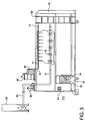
- FIG. 3 depicts the roll-off embodiment 310 with a means for introducing slurry reagents into the treatment vessel 310.
- Dry reagents can be stored in a portable storage silo or tank 82.
- the dry reagents can be distributed from the silo or tank 82 via a pressurized transfer line 84 to a slurry pump mixing apparatus 86.
- the slurry mixing apparatus 86 comprises a mix tank, slurry pump and distribution system. After the slurry is created, the slurried reagent may be injected into the treatment vessel by way of the reagent injection system.
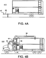
- FIG. 4A depicts a trailer embodiment of the treatment vessel 410.
- the treatment vessel may include a trailer tongue 85 with a coupler 87 in either a hand wheel type or a lever type.
- FIG. 4B depicts an embodiment of the treatment vessel, wherein the treatment vessel 510 is integrally coupled with a truck or tractor.
- the treatment vessel 510 further includes a high volume vacuum excavation system 88 and a condenser unit 90.
- the vacuum excavation system 88 includes a vacuum pump and drive means 92, a hose 94, and a rotating mast 96.
- This vacuum excavation system 88 facilitates high-pressure excavation of areas that are difficult to access with traditional excavation equipment, for example, contaminated media surrounding buried utilities. Because of the maneuverability of the hose 94 and the strong suction power of the system 88, the system 88 can excavate these areas without disruption and damage to nearby items such as utilities.
- the vacuum system 88 also contains a rotating mast 96, which permits the vacuum excavation system 88 to extend to areas that are not easily accessible by vehicle.
- the mast 96 connects to a series of special vacuum hoses and may be rotated over the area of excavation, wherein the vacuum hoses are situated to remove the contaminated material.
- the mast 96 facilitates vacuum excavation without the need to have the hose running through the contaminated area.
- the embodiment also includes a condenser unit 90 for the collection, separation and treatment of vapor and liquid contaminants separated from media by the treatment process.
- a condenser unit is particularly beneficial in treatment processes for treatment of, for example, manufactured gas plant (MGP) waste, also known as coal tar and it constituents.
- MGP manufactured gas plant
- FIG. 5A depicts an embodiment of the treatment vessel, wherein the treatment vessel 610 is a trailer typically pulled and spotted by a tractor-trailer truck.
- the long trailer embodiment 610 has the same features as other embodiments and may also contain multiple power sources and multiple discharge openings 48.
- FIG. 5B depicts an embodiment of the treatment vessel, wherein the treatment vessel 710 is configured on a self propelled remote controlled track mounted configuration 98.
- This embodiment contains an integral power unit 100 consisting of a combustion engine, an electric/ hydraulic distribution, and a drive system.
- the track unit can be remotely controlled at a site and placed in close proximity to the contaminated zone where media is extracted for treatment.
- the remote controlled excavation facilitates remediation of a contaminated area with limited intrusion into the contaminated area by remediation personnel.
- FIG. 6 depicts a heat injection system 102 including a mounting frame, cal rod heater system, a regenerative blower/vacuum system, electrical distribution and control panels and high temperature heat fittings connected to the plurality of interior injection systems 104. Dry heat is generated through the electrical powering of the system, followed by injection of the heat into the treatment vessel at varying temperatures and pressures. The heat acts as a reagent, volatilizing contaminated substrates such as polluted soils, sludge, sediments and Biosolids.
- the piping network 104 for the heat injection system may be the same as the piping network 18 for the reagent injection system.
- contaminated vapors are recovered and treated through the vapor recovery system 42, which comprises a regenerative vacuum unit 66 for recovery through the interior lines 46, and treatment of air stream contaminants through activated carbon units, catalytic/thermal oxidizers, and the like.
- the invention also relates to a method of treating toxic material and Biosolids preferably using an embodiment of the apparatus described above.
- the method comprises the steps of placing a batch of a solid or semi-solid contaminated substrate into a treatment vessel comprising an agitating means and a reagent injection means; introducing a treatment reagent into the treatment vessel via the reagent injection means; using the agitating means of the treatment vessel to agitate the contaminated substrate and the treatment reagent at ambient or elevated temperatures and at atmospheric or elevated pressures in the vessel for a time sufficient for the treatment reagent to extract in excess of 60% of the toxin from the substrate; removing the contaminant-laden (toxin-laden) reagent from the treatment vessel; removing the toxins from the reagent such that the reagent can be recycled for reuse; and removing the residue of the batch substrate from the treatment vessel.
- an optional step of reducing the particle size of the contaminated substrate may be employed. Reducing the particle size increases the exposed surface area of the material, which in turn allows for greater exposure to the reagent
- the particle size can be reduced by, for example, milling the soil in-situ to create small particles. Smaller particular size has been found to be particularly beneficial in weathered soils (e.g., soil comprised mainly of rock, gravel, and sand) contaminated with PCBs. The reduced particle size (and resulting increased surface area) of the contaminated weathered soils are more amenable to PCB extraction than their non-reduced counterparts. Further, it has been found that there is a much improved extraction in substrates milled to a -20 mesh.
- Another optional step entails the removal of water or moisture from the contaminated substrate prior to treatment.
- the removal of water or moisture allows for greater efficiency of the reagent. Water dilutes many of the contemplated reagents, reducing the reagents' concentration in the treatment vessel, and thus reducing the reagents' ability to effectively remove the contaminates from the substrate.
- a preliminary step of removing the water reduces the dilution and thus increases the effectiveness of the reagent
- the removal may be performed as a preliminary step by one or more conventional means such as air drying, filter pressing, or heat drying.
- a preferred pretreatment for use with contaminated soil sites uses an apparatus such as described in US patent 5,830,752 to mix and heat the soil in-situ to remove a significant amount of the water.
- the method may also be performed with the optional pretreatment step of improving the solubility of certain metal species in the substrate by using acid or base addition.
- substrates contaminated with hazardous metals are pretreated with a base or an acid such as nitric acid. If a sufficient amount of acid is used, the acid converts the metal components into acid salts such as nitrate salts.
- sulfuric and phosphoric acid may be employed, it is preferred that nitric acid be utilized if ammonia is the reagent of choice, because nitrate salts have a higher solubility in ammonia.
- the treatment vessel used in the method is preferably an embodiment of the treatment vessel discussed in detail above.
- alternate treatment vessels may be employed provided that they have a means for mixing the substrate, heating the substrate, and adding a reagent to the substrate.
- the selection of the reagent will be contingent on conditions such as composition of the substrate and composition of the toxic materials or Biosolids.
- conditions such as composition of the substrate and composition of the toxic materials or Biosolids.
- the most efficient and economic processes disclosed herein for the vast majority of conditions involve the use of ammonia and water. Liquid ammonia is readily available, because it is employed as a fertilizer in agricultural operations. Consequently, it is also relatively inexpensive.
- Ammonia boils at -33 degrees centigrade requiring in some cases cooling and/or that the solutions be pressurized. In some cases, it may be advantageous to combine the ammonia with another solvating substance such as mineral oil or a hydrocarbon such as hexane.
- Another solvating substance such as mineral oil or a hydrocarbon such as hexane.
- the selection of the co solvent used will be dictated by the nature of the toxin to be removed.
- the ratio of ammonia or ammonical solution to contaminated substrate is preferably between about .25/1 and 1000/1 on a weight basis and more preferably between 1/1 and 5/1.
- the combination of the apparatus of the invention with ammonia reagent is preferably used to further process the contaminated substrate to produce acceptable land application fertilizer.
- a composition of dewatered sewage sludge is placed into the pressure sealable treatment vessel.
- the pressure in the vessel may then be reduced slightly below atmospheric such that injected ammonia will transition to gaseous state.
- Anhydrous ammonia is introduced to the composition in the treatment vessel via the reagent injection system.
- the composition is mixed by the mixing device at ambient or elevated temperatures in the presence of the ammonia gas for a time sufficient for the ammonia to reduce pathogenic microorganisms to levels acceptable under regulatory standards for land application. Heat may be applied inside the vessel to increase the rate of pathogen reduction and to thermally strip volatile toxins from the composition.
- the ammonia gas is then removed through the vapor recovery system, from which it may be stored or processed for further use. Any volatile contaminants removed by the vapor recovery system can be processed out of the ammonia by known filtering or extraction processes.
- Further treatment of the solid material may be desirable to bring the level of the residual toxin down below a target such as a regulatory criterion.
- a target such as a regulatory criterion.
- Repeated treatment of the solid matrix with ammonia or ammonical solutions as described above can be performed under similar operating conditions. Repeated treatment will further reduce the contaminant concentration and may be necessary if the original treatment does not bring the contaminate concentration below the desired goal (e.g., regulatory limit, site-specific clean-up criteria).
- the process can be modified by increasing the pressure in the vessel above atmospheric levels to maintain the reagent in liquid form.
- the reagent injection system is then used to spray an ammonia/water mixture into the composition as it is being mixed to thoroughly wash the composition.
- the ammonia/water mixture is separated from the composition in the treatment vessel and removed by the reagent recovery system, from which it may be stored or processed for further use. Separation of the ammonical solutions can be performed by conventional means such as filtration, precipitation, decantation, and centrifugation and so on.
- ammonical solutions containing the toxins can be combined into a separate vessel for further treatment, i.e., detoxification by introducing an absorbent such as activated carbon, clay, ion exchange medium or any commonly known absorbent.
- an absorbent such as activated carbon, clay, ion exchange medium or any commonly known absorbent.
- the ammonia or ammonical solution may be used for treatment of additional contaminated substrate.
- Any metals or other toxins removed by the reagent recovery system can be processed out of the ammonia by known filtering or extraction processes. The mixing with the ammonia wash reagent should also be sufficient to reduce the pathogenic organisms.
- the composition will likely contain a substantial amount of residual ammonia.
- This residue can be fixed as a nitrogenous fertilizer salt by mixing phosphoric acid into the decontaminated composition. This can be done inside the vessel using the mixing device to mix the acid thoroughly into the composition and elevating the temperature to speed the reaction. Any released vapor can be extracted via the vapor recovery system. Potassium and/or phosphorus and pH balancers may likewise be mixed into the composition in such ratios to the nitrogen and to each other that the composition is a balanced fertilizer.
- the step is particularly beneficial with Biosolids.
- the Biosolids Prior to treatment, the Biosolids have many of the organic characteristics necessary to make effective fertilizer, but may contain toxic materials such as heavy metals or pathogens at levels above the regulatory limits for disposal as fertilizer. After treatment, the contaminated materials have been removed and the Biosolid material is nitrogen rich from the ammonia wash treatment.
- the residual ammonia may be fixed by the introduction to the treated Biosolids of one or more of nitric acid, phosphoric acid, or sulfuric acid.
- phosphorus and potassium may also be added to the treated Biosolids.
- the phosphorous may be added by the addition of phosphoric acid and the potassium may be added by the addition of potassium chloride, but other means are available.
- the amount of phosphorous and potassium to be added is dependent on the original concentration of nitrogen in the treated Biosolids, and the desired ratio of nitrogen to phosphorous to potassium in the fertilizer. Typical ratios include 1-1-1, 1-2-1, 1-2-3, 3-1-1, and so on.
- the mixing and blending of these ammonia salts, phosphorous and potassium into the Biosolid can be done inside the treatment vessel by the mixing device.
- Contaminated sludge from a New England harbor was dredged using conventional means.
- the sludge was heat dried to remove residual water. 56.1 grams of the dried sludge was placed in a pressure treatment vessel and the vessel was charged with 1000 ml of anhydrous ammonia. The temperature was increased to 40°C and held there for 30 minutes while stirring at 800 rpms. The ammonia was drained by filtration from the sludge and the sludge analyzed for residual organics. Table I lists the results.
- Contaminant Starting Material ppm
- Washed Material ppm
- PCB 9453 338 Anthracene 7.2 ND Benzopyrene 8.5 ND 1,3 dichlorobenzene 31 4.7 Pyrene 14 5.4
- the solid material from example 1 was washed a second time using the same procedure described in example 1.
- the twice washed material had a residual PCB level of 23 ppm.
- the solid material from example 2 was washed a third time using the same procedure as described in example 1.
- the thrice washed material had a residual PCB level of 0.2 ppm.
- Soil was excavated in a conventional manner from a site in Texas.
- the soil was doped with 500 ppm of PCB.
- 54.4 grams of the doped soil was added to a treatment cell along with 1000 ml of anhydrous ammonia.
- the mixture was stirred at 800 rpms for 5 minutes.
- the ammonia was filtered away from the solid soil matrix.
- the residual soil was analyzed for PCB and found to contain 7 ppm PCB.
- Weathered soil containing dioxins and pentachlorophenol was obtained from a West coast industrial site using conventional excavation techniques. 120 grams of the soil was dried by heat treatment to remove residual water, and then placed in a treatment cell. 1000 ml of anhydrous ammonia was added and the mixture was stirred at 800 rpms for 10 minutes. The ammonia was filtered away from the soil and the soil was analyzed for pentachlorophenol and dioxins. Table II lists the results. Contaminant Starting level ppm Treated level PPM Pentachlorophenol 42 3 Dioxin .9 .005
- One ton of sludge from a commercial bakery process is placed in a conventional roll-off container or treatment vessel.
- the sludge contained approximately 60% solids.
- 120 pounds of anhydrous ammonia was added with MITU mixing. The mixture was mixed for 30 minutes. 167 pounds of phosphoric acid and 200 pounds of potassium chloride was added and mixing was continued for 30 minutes.
- the entire batch was dried using the MTTU drying process to yield 1,687 pounds of fertilizer having 10/10/10 N/P/K.
- the methods of the invention can be carried out at a fixed plant or using a mobile apparatus.
- the drawings show several embodiments of a mobile apparatus. However, it should be understood that the various elements of the apparatus can be used in or at a fixed facility as well.
Landscapes
- Engineering & Computer Science (AREA)
- Environmental & Geological Engineering (AREA)
- Life Sciences & Earth Sciences (AREA)
- Chemical & Material Sciences (AREA)
- Organic Chemistry (AREA)
- Soil Sciences (AREA)
- Hydrology & Water Resources (AREA)
- Water Supply & Treatment (AREA)
- Mechanical Engineering (AREA)
- Botany (AREA)
- Processing Of Solid Wastes (AREA)
- Treatment Of Sludge (AREA)
- Fertilizers (AREA)
- Medicines Containing Material From Animals Or Micro-Organisms (AREA)
- Medicines Containing Antibodies Or Antigens For Use As Internal Diagnostic Agents (AREA)
Claims (9)
- Ein Verfahren zum Behandeln von mit Biofeststoffen und anderen Toxinen kontaminiertem Schlamm, das die folgenden Schritte beinhaltet:Platzieren des Schlamms in ein Behandlungsgefäß (10);Einführen eines Behandlungsreagens, das eine Ammoniakmischung beinhaltet, in das Behandlungsgefäß (10);Rühren des Schlamms und der Ammoniakmischung bei Umgebungstemperatur oder erhöhter Temperatur und bei atmosphärischem oder erhöhtem Druck in dem Gefäß (10) für eine Zeit, die dazu ausreicht, dass die Ammoniakmischung mehr als 60 % des Toxins aus dem Schlamm extrahiert;Entfernen der Ammoniakmischung und der Toxine aus dem Behandlungsgefäß (10)Entfernen des Toxins aus dem Behandlungsreagens, so dass die Ammoniakmischung zur Wiederverwendung wiederverwertet werden kann;Entfernen des dekontaminierten Schlamms aus dem Behandlungsgefäß (10);wobei das Behandlungsgefäß ein Reagens-Einspritzsystem (16) zum Einspritzen eines Reagens in das Gefäß, eine Mischvorrichtung (22, 122, 222) zum Mischen des Schlamms mit dem Reagens innerhalb des Gefäßes beinhaltet,dadurch gekennzeichnet, dass das Verfahren ferner den Schritt des Bindens des in dem behandelten Schlamm übrig gebliebenen Restammoniaks als ein Ammoniaksalz beinhaltet, und wobei das Behandlungsgefäß (10) ein Gefäß mit einer abdichtbaren Tür (12), die geöffnet werden kann, um den Schlamm in das Gefäß zu laden, und die geschlossen werden kann, um eine Dampfabdichtung bereitzustellen, ein Erhitzersystem zum Erhitzen des Schlamms innerhalb des Gefäßes, ein Dampfrückgewinnungssystem (42) zum Rückgewinnen von innerhalb des Gefäßes abgegebenen Dämpfen und einen Abführmechanismus (48, 52) zum Abführen der behandelten Zusammensetzung beinhaltet.
- Verfahren gemäß Anspruch 1, wobei die Ammoniakmischung eine flüssiges Ammoniak/Solvatisiersubstanz-Mischung beinhaltet, die 0-95 Gewichts-% Wasser beinhaltet.
- Verfahren gemäß Anspruch 2, wobei nach der Behandlung in dem dekontaminierten Schlamm verbleibender Restammoniak unter Verwendung einer oder mehrerer von Salpetersäure, Phosphorsäure oder Schwefelsäure gebunden wird.
- Verfahren gemäß Anspruch 3, wobei Phosphor und Kalium in Verhältnissen zu dem behandelten Schlamm hinzugefügt werden, um ein Düngemittel zu schaffen.
- Verfahren gemäß Anspruch 4, wobei das Düngemittel ein Verhältnis von Stickstoff zu Phosphor zu Kalium von eins zu eins zu eins beinhaltet.
- Verfahren gemäß Anspruch 1, wobei die Toxine durch eines oder mehrere von Kohlenstoffabsorption, Ionenaustauschabsorption, Dekantation und Zentrifugierung oder Filterung aus dem Behandlungsreagens entfernt werden.
- Verfahren gemäß Anspruch 1, wobei das Verfahren ferner einen Schritt des Verringerns der Partikelgröße des Schlamms vor der Behandlung beinhaltet.
- Verfahren gemäß Anspruch 1, wobei das Verfahren ferner einen Schritt des Entfernens oder Verringerns des Wasser- oder Feuchtigkeitsgehalts in dem Schlamm vor der Behandlung beinhaltet.
- Verfahren gemäß Anspruch 1, wobei das Gefäß (10) ferner ein Reagens-Rückgewinnungssystem umfasst.
Applications Claiming Priority (2)
| Application Number | Priority Date | Filing Date | Title |
|---|---|---|---|
| US47343903P | 2003-05-22 | 2003-05-22 | |
| PCT/US2004/016109 WO2004105974A2 (en) | 2003-05-22 | 2004-05-20 | Process and apparatus for further processing of sewage sludge and other materials to reduce pathogens and toxins |
Publications (2)
| Publication Number | Publication Date |
|---|---|
| EP1633502A2 EP1633502A2 (de) | 2006-03-15 |
| EP1633502B1 true EP1633502B1 (de) | 2012-04-11 |
Family
ID=33490602
Family Applications (1)
| Application Number | Title | Priority Date | Filing Date |
|---|---|---|---|
| EP04753009A Expired - Lifetime EP1633502B1 (de) | 2003-05-22 | 2004-05-20 | Verfahren zur behandlung von mit biofeststoffen und anderen toxinen kontaminiertem schlamm |
Country Status (6)
| Country | Link |
|---|---|
| US (1) | US7972408B2 (de) |
| EP (1) | EP1633502B1 (de) |
| AT (1) | ATE552924T1 (de) |
| CA (1) | CA2526624C (de) |
| DK (1) | DK1633502T3 (de) |
| WO (1) | WO2004105974A2 (de) |
Families Citing this family (19)
| Publication number | Priority date | Publication date | Assignee | Title |
|---|---|---|---|---|
| US7951988B2 (en) | 2009-04-01 | 2011-05-31 | Earth Renewal Group, Llc | Aqueous phase oxidation process |
| US7915474B2 (en) | 2009-04-01 | 2011-03-29 | Earth Renewal Group, Llc | Aqueous phase oxidation process |
| US8168847B2 (en) | 2009-04-01 | 2012-05-01 | Earth Renewal Group, Llc | Aqueous phase oxidation process |
| US8115047B2 (en) | 2009-04-01 | 2012-02-14 | Earth Renewal Group, Llc | Aqueous phase oxidation process |
| US8481800B2 (en) | 2009-04-01 | 2013-07-09 | Earth Renewal Group, Llc | Aqueous phase oxidation process |
| US9272936B2 (en) | 2009-04-01 | 2016-03-01 | Earth Renewal Group, Llc | Waste treatment process |
| KR100958292B1 (ko) * | 2009-10-09 | 2010-05-19 | 주식회사 윈텍에이티에스 | 오염토양 정화장치 |
| KR101014188B1 (ko) | 2010-03-03 | 2011-02-14 | 주식회사 윈텍에이티에스 | 오염토양 정화장치 |
| US9108864B2 (en) | 2011-09-15 | 2015-08-18 | Storm Drain Technologies, Llc | Construction site water treatment system and methods |
| US8889000B2 (en) | 2011-09-15 | 2014-11-18 | Storm Drain Technologies, Llc | Apparatus, methods, and system for treatment of stormwater and waste fluids |
| US8518339B1 (en) * | 2011-12-23 | 2013-08-27 | Peter Jude | Systems, components, and methods for sterilizing medical waste |
| FI123959B (fi) * | 2012-02-03 | 2014-01-15 | Reima Pyy | Menetelmä ja laite puhdistamolietteen desinfioimiseksi |
| US9701323B2 (en) | 2015-04-06 | 2017-07-11 | Bedloe Industries Llc | Railcar coupler |
| US10239016B2 (en) | 2016-12-07 | 2019-03-26 | Nuorganics LLC | Systems and methods for nitrogen recovery from a gas stream |
| CA2992063A1 (en) | 2017-01-16 | 2018-07-16 | Nuorganics LLC | Systems and methods for recovering nitrogenous compounds from a gas stream |
| CN110788131B (zh) * | 2019-12-01 | 2021-11-05 | 山东省环境保护科学研究设计院有限公司 | 一种修复土壤方法及其装置 |
| CN111018298B (zh) * | 2019-12-28 | 2021-11-30 | 泗洪仁益自来水有限公司 | 一种水利除淤泥用离心式淤泥脱水设备的使用方法 |
| CN111389899A (zh) * | 2020-03-26 | 2020-07-10 | 甘肃省农业科学院土壤肥料与节水农业研究所 | 一种污染农业土壤过滤修复装置 |
| CN114833182B (zh) * | 2022-03-29 | 2023-10-20 | 浙江工贸职业技术学院 | 一种连续作业的土壤治理浆液注入装置和土壤处理方法 |
Family Cites Families (10)
| Publication number | Priority date | Publication date | Assignee | Title |
|---|---|---|---|---|
| US3841464A (en) * | 1972-10-30 | 1974-10-15 | Lippmann Inc | Hydraulically folding material discharge conveyor |
| US4028087A (en) * | 1976-02-23 | 1977-06-07 | Tennessee Valley Authority | Fertilizer processes incorporating scrubbed flue gas sludge byproduct |
| US5232584A (en) * | 1990-07-11 | 1993-08-03 | International Environmental Systems, Inc., Usa | Method and apparatus for purifying and compacting solid wastes |
| US5272833A (en) * | 1990-08-28 | 1993-12-28 | Asphalt Product Technologies, Inc. | Soil remediation apparatus and method for same |
| US5495062A (en) * | 1994-09-12 | 1996-02-27 | Commodore Laboratories, Inc. | Methods of decontaminating nuclear waste-containing soil |
| US5916448A (en) * | 1996-08-23 | 1999-06-29 | Hazen & Sawyer P.C. | Chemical conditioning of liquid and semi-liquid sludge for dewatering, odor control, pathogen control, nutrient enhancement of the residual, and handling characteristics |
| US6409788B1 (en) * | 1998-01-23 | 2002-06-25 | Crystal Peak Farms | Methods for producing fertilizers and feed supplements from agricultural and industrial wastes |
| US6409789B1 (en) * | 2000-02-07 | 2002-06-25 | R. Gene Gilbert | Organic biosolid waste treatment process for resource transformation, regeneration, and utilization |
| AU2003301193A1 (en) * | 2002-12-19 | 2004-07-14 | Bluewater Investments, Inc. | Methods of controlling chemical self-heating of organic-containing materials |
| US7008538B2 (en) * | 2003-08-20 | 2006-03-07 | Kasparian Kaspar A | Single vessel multi-zone wastewater bio-treatment system |
-
2004
- 2004-05-20 DK DK04753009.2T patent/DK1633502T3/da active
- 2004-05-20 CA CA2526624A patent/CA2526624C/en not_active Expired - Fee Related
- 2004-05-20 EP EP04753009A patent/EP1633502B1/de not_active Expired - Lifetime
- 2004-05-20 US US10/557,941 patent/US7972408B2/en active Active
- 2004-05-20 WO PCT/US2004/016109 patent/WO2004105974A2/en not_active Ceased
- 2004-05-20 AT AT04753009T patent/ATE552924T1/de active
Also Published As
| Publication number | Publication date |
|---|---|
| WO2004105974A2 (en) | 2004-12-09 |
| DK1633502T3 (da) | 2012-07-16 |
| US20070023342A1 (en) | 2007-02-01 |
| ATE552924T1 (de) | 2012-04-15 |
| US7972408B2 (en) | 2011-07-05 |
| EP1633502A2 (de) | 2006-03-15 |
| WO2004105974A3 (en) | 2005-09-15 |
| CA2526624A1 (en) | 2004-12-09 |
| CA2526624C (en) | 2012-02-21 |
Similar Documents
| Publication | Publication Date | Title |
|---|---|---|
| CA2526624C (en) | Process and apparatus for further processing of sewage sludge and other materials to reduce pathogens and toxins | |
| US4913586A (en) | Mixture for detoxification of contaminated soil | |
| US5631160A (en) | Method for in situ soil remediation | |
| US5605417A (en) | Method and apparatus for improving degradation of an unsecured landfill | |
| US6960330B1 (en) | Method for reducing H2S contamination | |
| US5563066A (en) | Method and apparatus for remediating contaminated soil containing organic compounds | |
| US8858806B1 (en) | Method for reducing contamination | |
| US4794871A (en) | Method and installation for the treatment of material contaminated with toxic organic compounds | |
| US5514286A (en) | Thermal desorption unit | |
| MXPA97001827A (en) | Methods to decontaminate lands that continue metallic noci | |
| US5656178A (en) | Method for treatment of contaminated materials with superheated steam thermal desorption and recycle | |
| Guangwei et al. | In-situ stabilisation followed by ex-situ composting for treatment and disposal of heavy metals polluted sediments | |
| Felsot | Options for cleanup and disposal of pesticide wastes generated on a small‐scale | |
| US9623456B2 (en) | Mobile soil treatment unit | |
| Hopper | Cleaning up contaminated waste sites | |
| Ross | Slurry‐phase bioremediation: Case studies and cost comparisons | |
| JP2004066193A (ja) | 汚染土壌の浄化方法 | |
| US9737920B2 (en) | Method and apparatus for extracting contaminants from soil and from animal manure | |
| US7344489B2 (en) | Sludge treatment method | |
| EP1979274A1 (de) | Abfallbearbeitungsverfahren | |
| WO2001014261A1 (en) | Method of treating incineration ashes with sulfate reducing bacteria | |
| CN112044949A (zh) | 一种有机污染土壤处理系统与处理方法 | |
| Valenti | Cleaning soil without incineration | |
| Nitta et al. | ORGANIC DECOMPOSING SYSTEM FOR SUPPLYING NUTRIENTS IN CLOSED ECOLOGY EXPERIMENT FACILITES (CEEF) | |
| JP2004097962A (ja) | 汚染土壌の浄化方法 |
Legal Events
| Date | Code | Title | Description |
|---|---|---|---|
| PUAI | Public reference made under article 153(3) epc to a published international application that has entered the european phase |
Free format text: ORIGINAL CODE: 0009012 |
|
| 17P | Request for examination filed |
Effective date: 20051216 |
|
| AK | Designated contracting states |
Kind code of ref document: A2 Designated state(s): AT BE BG CH CY CZ DE DK EE ES FI FR GB GR HU IE IT LI LU MC NL PL PT RO SE SI SK TR |
|
| AX | Request for extension of the european patent |
Extension state: AL HR LT LV MK |
|
| DAX | Request for extension of the european patent (deleted) | ||
| 17Q | First examination report despatched |
Effective date: 20090325 |
|
| GRAP | Despatch of communication of intention to grant a patent |
Free format text: ORIGINAL CODE: EPIDOSNIGR1 |
|
| RIC1 | Information provided on ipc code assigned before grant |
Ipc: B09C 1/08 20060101ALI20110907BHEP Ipc: B09C 1/02 20060101AFI20110907BHEP Ipc: C05F 5/00 20060101ALI20110907BHEP Ipc: C02F 11/08 20060101ALI20110907BHEP Ipc: C05F 7/00 20060101ALI20110907BHEP |
|
| RTI1 | Title (correction) |
Free format text: PROCESS FOR TREATING SLUDGE CONTAMINATED WITH BIOSOLIDS AND OTHER TOXINS |
|
| GRAS | Grant fee paid |
Free format text: ORIGINAL CODE: EPIDOSNIGR3 |
|
| GRAA | (expected) grant |
Free format text: ORIGINAL CODE: 0009210 |
|
| AK | Designated contracting states |
Kind code of ref document: B1 Designated state(s): AT BE BG CH CY CZ DE DK EE ES FI FR GB GR HU IE IT LI LU MC NL PL PT RO SE SI SK TR |
|
| REG | Reference to a national code |
Ref country code: GB Ref legal event code: FG4D |
|
| REG | Reference to a national code |
Ref country code: CH Ref legal event code: EP |
|
| REG | Reference to a national code |
Ref country code: AT Ref legal event code: REF Ref document number: 552924 Country of ref document: AT Kind code of ref document: T Effective date: 20120415 |
|
| REG | Reference to a national code |
Ref country code: IE Ref legal event code: FG4D |
|
| RAP2 | Party data changed (patent owner data changed or rights of a patent transferred) |
Owner name: BRUSO, BRUCE L. |
|
| REG | Reference to a national code |
Ref country code: DE Ref legal event code: R096 Ref document number: 602004037324 Country of ref document: DE Effective date: 20120606 |
|
| REG | Reference to a national code |
Ref country code: NL Ref legal event code: T3 |
|
| REG | Reference to a national code |
Ref country code: DK Ref legal event code: T3 |
|
| REG | Reference to a national code |
Ref country code: SE Ref legal event code: TRGR |
|
| REG | Reference to a national code |
Ref country code: AT Ref legal event code: MK05 Ref document number: 552924 Country of ref document: AT Kind code of ref document: T Effective date: 20120411 |
|
| PG25 | Lapsed in a contracting state [announced via postgrant information from national office to epo] |
Ref country code: PL Free format text: LAPSE BECAUSE OF FAILURE TO SUBMIT A TRANSLATION OF THE DESCRIPTION OR TO PAY THE FEE WITHIN THE PRESCRIBED TIME-LIMIT Effective date: 20120411 Ref country code: CY Free format text: LAPSE BECAUSE OF FAILURE TO SUBMIT A TRANSLATION OF THE DESCRIPTION OR TO PAY THE FEE WITHIN THE PRESCRIBED TIME-LIMIT Effective date: 20120411 Ref country code: FI Free format text: LAPSE BECAUSE OF FAILURE TO SUBMIT A TRANSLATION OF THE DESCRIPTION OR TO PAY THE FEE WITHIN THE PRESCRIBED TIME-LIMIT Effective date: 20120411 |
|
| PG25 | Lapsed in a contracting state [announced via postgrant information from national office to epo] |
Ref country code: SI Free format text: LAPSE BECAUSE OF FAILURE TO SUBMIT A TRANSLATION OF THE DESCRIPTION OR TO PAY THE FEE WITHIN THE PRESCRIBED TIME-LIMIT Effective date: 20120411 Ref country code: PT Free format text: LAPSE BECAUSE OF FAILURE TO SUBMIT A TRANSLATION OF THE DESCRIPTION OR TO PAY THE FEE WITHIN THE PRESCRIBED TIME-LIMIT Effective date: 20120813 Ref country code: GR Free format text: LAPSE BECAUSE OF FAILURE TO SUBMIT A TRANSLATION OF THE DESCRIPTION OR TO PAY THE FEE WITHIN THE PRESCRIBED TIME-LIMIT Effective date: 20120712 |
|
| PG25 | Lapsed in a contracting state [announced via postgrant information from national office to epo] |
Ref country code: MC Free format text: LAPSE BECAUSE OF NON-PAYMENT OF DUE FEES Effective date: 20120531 |
|
| REG | Reference to a national code |
Ref country code: CH Ref legal event code: PL |
|
| PG25 | Lapsed in a contracting state [announced via postgrant information from national office to epo] |
Ref country code: RO Free format text: LAPSE BECAUSE OF FAILURE TO SUBMIT A TRANSLATION OF THE DESCRIPTION OR TO PAY THE FEE WITHIN THE PRESCRIBED TIME-LIMIT Effective date: 20120411 Ref country code: SK Free format text: LAPSE BECAUSE OF FAILURE TO SUBMIT A TRANSLATION OF THE DESCRIPTION OR TO PAY THE FEE WITHIN THE PRESCRIBED TIME-LIMIT Effective date: 20120411 Ref country code: CH Free format text: LAPSE BECAUSE OF NON-PAYMENT OF DUE FEES Effective date: 20120531 Ref country code: EE Free format text: LAPSE BECAUSE OF FAILURE TO SUBMIT A TRANSLATION OF THE DESCRIPTION OR TO PAY THE FEE WITHIN THE PRESCRIBED TIME-LIMIT Effective date: 20120411 Ref country code: LI Free format text: LAPSE BECAUSE OF NON-PAYMENT OF DUE FEES Effective date: 20120531 Ref country code: AT Free format text: LAPSE BECAUSE OF FAILURE TO SUBMIT A TRANSLATION OF THE DESCRIPTION OR TO PAY THE FEE WITHIN THE PRESCRIBED TIME-LIMIT Effective date: 20120411 Ref country code: CZ Free format text: LAPSE BECAUSE OF FAILURE TO SUBMIT A TRANSLATION OF THE DESCRIPTION OR TO PAY THE FEE WITHIN THE PRESCRIBED TIME-LIMIT Effective date: 20120411 |
|
| PLBE | No opposition filed within time limit |
Free format text: ORIGINAL CODE: 0009261 |
|
| STAA | Information on the status of an ep patent application or granted ep patent |
Free format text: STATUS: NO OPPOSITION FILED WITHIN TIME LIMIT |
|
| PG25 | Lapsed in a contracting state [announced via postgrant information from national office to epo] |
Ref country code: IT Free format text: LAPSE BECAUSE OF FAILURE TO SUBMIT A TRANSLATION OF THE DESCRIPTION OR TO PAY THE FEE WITHIN THE PRESCRIBED TIME-LIMIT Effective date: 20120411 |
|
| 26N | No opposition filed |
Effective date: 20130114 |
|
| PG25 | Lapsed in a contracting state [announced via postgrant information from national office to epo] |
Ref country code: ES Free format text: LAPSE BECAUSE OF FAILURE TO SUBMIT A TRANSLATION OF THE DESCRIPTION OR TO PAY THE FEE WITHIN THE PRESCRIBED TIME-LIMIT Effective date: 20120722 |
|
| REG | Reference to a national code |
Ref country code: DE Ref legal event code: R097 Ref document number: 602004037324 Country of ref document: DE Effective date: 20130114 |
|
| PG25 | Lapsed in a contracting state [announced via postgrant information from national office to epo] |
Ref country code: BG Free format text: LAPSE BECAUSE OF FAILURE TO SUBMIT A TRANSLATION OF THE DESCRIPTION OR TO PAY THE FEE WITHIN THE PRESCRIBED TIME-LIMIT Effective date: 20120711 |
|
| PG25 | Lapsed in a contracting state [announced via postgrant information from national office to epo] |
Ref country code: TR Free format text: LAPSE BECAUSE OF FAILURE TO SUBMIT A TRANSLATION OF THE DESCRIPTION OR TO PAY THE FEE WITHIN THE PRESCRIBED TIME-LIMIT Effective date: 20120411 |
|
| PG25 | Lapsed in a contracting state [announced via postgrant information from national office to epo] |
Ref country code: LU Free format text: LAPSE BECAUSE OF NON-PAYMENT OF DUE FEES Effective date: 20120520 |
|
| PG25 | Lapsed in a contracting state [announced via postgrant information from national office to epo] |
Ref country code: HU Free format text: LAPSE BECAUSE OF FAILURE TO SUBMIT A TRANSLATION OF THE DESCRIPTION OR TO PAY THE FEE WITHIN THE PRESCRIBED TIME-LIMIT Effective date: 20040520 |
|
| PGFP | Annual fee paid to national office [announced via postgrant information from national office to epo] |
Ref country code: DK Payment date: 20141115 Year of fee payment: 11 |
|
| PGFP | Annual fee paid to national office [announced via postgrant information from national office to epo] |
Ref country code: GB Payment date: 20141117 Year of fee payment: 11 Ref country code: SE Payment date: 20141117 Year of fee payment: 11 Ref country code: IE Payment date: 20141118 Year of fee payment: 11 Ref country code: DE Payment date: 20141201 Year of fee payment: 11 |
|
| PGFP | Annual fee paid to national office [announced via postgrant information from national office to epo] |
Ref country code: NL Payment date: 20141119 Year of fee payment: 11 Ref country code: FR Payment date: 20141117 Year of fee payment: 11 |
|
| PGFP | Annual fee paid to national office [announced via postgrant information from national office to epo] |
Ref country code: BE Payment date: 20141120 Year of fee payment: 11 |
|
| REG | Reference to a national code |
Ref country code: DE Ref legal event code: R119 Ref document number: 602004037324 Country of ref document: DE |
|
| REG | Reference to a national code |
Ref country code: DK Ref legal event code: EBP Effective date: 20150531 |
|
| GBPC | Gb: european patent ceased through non-payment of renewal fee |
Effective date: 20150520 |
|
| REG | Reference to a national code |
Ref country code: NL Ref legal event code: MM Effective date: 20150601 |
|
| REG | Reference to a national code |
Ref country code: IE Ref legal event code: MM4A |
|
| REG | Reference to a national code |
Ref country code: FR Ref legal event code: ST Effective date: 20160129 |
|
| PG25 | Lapsed in a contracting state [announced via postgrant information from national office to epo] |
Ref country code: SE Free format text: LAPSE BECAUSE OF NON-PAYMENT OF DUE FEES Effective date: 20150521 |
|
| PG25 | Lapsed in a contracting state [announced via postgrant information from national office to epo] |
Ref country code: GB Free format text: LAPSE BECAUSE OF NON-PAYMENT OF DUE FEES Effective date: 20150520 Ref country code: NL Free format text: LAPSE BECAUSE OF NON-PAYMENT OF DUE FEES Effective date: 20150601 Ref country code: IE Free format text: LAPSE BECAUSE OF NON-PAYMENT OF DUE FEES Effective date: 20150520 Ref country code: DK Free format text: LAPSE BECAUSE OF NON-PAYMENT OF DUE FEES Effective date: 20150531 Ref country code: DE Free format text: LAPSE BECAUSE OF NON-PAYMENT OF DUE FEES Effective date: 20151201 |
|
| PG25 | Lapsed in a contracting state [announced via postgrant information from national office to epo] |
Ref country code: FR Free format text: LAPSE BECAUSE OF NON-PAYMENT OF DUE FEES Effective date: 20150601 |
|
| PG25 | Lapsed in a contracting state [announced via postgrant information from national office to epo] |
Ref country code: BE Free format text: LAPSE BECAUSE OF NON-PAYMENT OF DUE FEES Effective date: 20150531 |