EP1633656B1 - Distributeur de support, par exemple, d'une bande alveolaire thermoformee - Google Patents
Distributeur de support, par exemple, d'une bande alveolaire thermoformee Download PDFInfo
- Publication number
- EP1633656B1 EP1633656B1 EP04735872A EP04735872A EP1633656B1 EP 1633656 B1 EP1633656 B1 EP 1633656B1 EP 04735872 A EP04735872 A EP 04735872A EP 04735872 A EP04735872 A EP 04735872A EP 1633656 B1 EP1633656 B1 EP 1633656B1
- Authority
- EP
- European Patent Office
- Prior art keywords
- dispenser
- holding means
- releasing
- holding
- engaging
- Prior art date
- Legal status (The legal status is an assumption and is not a legal conclusion. Google has not performed a legal analysis and makes no representation as to the accuracy of the status listed.)
- Expired - Lifetime
Links
- 238000000034 method Methods 0.000 claims abstract description 37
- 238000006073 displacement reaction Methods 0.000 claims abstract description 11
- 230000003578 releasing effect Effects 0.000 claims description 59
- 238000003780 insertion Methods 0.000 claims description 3
- 230000037431 insertion Effects 0.000 claims description 3
- 230000007246 mechanism Effects 0.000 abstract description 4
- 239000003814 drug Substances 0.000 description 9
- 229940079593 drug Drugs 0.000 description 9
- 239000000463 material Substances 0.000 description 5
- 230000006835 compression Effects 0.000 description 2
- 238000007906 compression Methods 0.000 description 2
- 238000007373 indentation Methods 0.000 description 2
- 239000006187 pill Substances 0.000 description 2
- 235000019504 cigarettes Nutrition 0.000 description 1
- 235000009508 confectionery Nutrition 0.000 description 1
- 239000011888 foil Substances 0.000 description 1
- 229910052738 indium Inorganic materials 0.000 description 1
- 238000004519 manufacturing process Methods 0.000 description 1
- 239000002184 metal Substances 0.000 description 1
- 238000000465 moulding Methods 0.000 description 1
- 238000007789 sealing Methods 0.000 description 1
- 239000000126 substance Substances 0.000 description 1
- 231100000331 toxic Toxicity 0.000 description 1
- 230000002588 toxic effect Effects 0.000 description 1
- 238000003466 welding Methods 0.000 description 1
Images


Classifications
-
- B—PERFORMING OPERATIONS; TRANSPORTING
- B65—CONVEYING; PACKING; STORING; HANDLING THIN OR FILAMENTARY MATERIAL
- B65D—CONTAINERS FOR STORAGE OR TRANSPORT OF ARTICLES OR MATERIALS, e.g. BAGS, BARRELS, BOTTLES, BOXES, CANS, CARTONS, CRATES, DRUMS, JARS, TANKS, HOPPERS, FORWARDING CONTAINERS; ACCESSORIES, CLOSURES, OR FITTINGS THEREFOR; PACKAGING ELEMENTS; PACKAGES
- B65D83/00—Containers or packages with special means for dispensing contents
- B65D83/04—Containers or packages with special means for dispensing contents for dispensing annular, disc-shaped, spherical or like small articles, e.g. tablets or pills
- B65D83/0445—Containers or packages with special means for dispensing contents for dispensing annular, disc-shaped, spherical or like small articles, e.g. tablets or pills all the articles being stored in individual compartments
- B65D83/0463—Containers or packages with special means for dispensing contents for dispensing annular, disc-shaped, spherical or like small articles, e.g. tablets or pills all the articles being stored in individual compartments formed in a band or a blisterweb, inserted in a dispensing device or container
-
- B—PERFORMING OPERATIONS; TRANSPORTING
- B65—CONVEYING; PACKING; STORING; HANDLING THIN OR FILAMENTARY MATERIAL
- B65D—CONTAINERS FOR STORAGE OR TRANSPORT OF ARTICLES OR MATERIALS, e.g. BAGS, BARRELS, BOTTLES, BOXES, CANS, CARTONS, CRATES, DRUMS, JARS, TANKS, HOPPERS, FORWARDING CONTAINERS; ACCESSORIES, CLOSURES, OR FITTINGS THEREFOR; PACKAGING ELEMENTS; PACKAGES
- B65D2585/00—Containers, packaging elements or packages specially adapted for particular articles or materials
- B65D2585/56—Containers, packaging elements or packages specially adapted for particular articles or materials for medicinal tablets or pills
Definitions
- the present Invention relates to a dispenser for holding a means for dispensing units, such as pills, tablets, sweets, which dispenser is resistant to (or prevents) children's access to the units.
- This holding means may be a blister card or other means holding the units and from which a user may access one or more units.
- the dispenser performs the function of preventing (or making difficult) access to the units when the holding means Is held by the dispenser.
- the mechanism may be hiden by e.g. requiring the combined operation of multiple buttons or the like, where the child would normally focus only on one.
- the present Invention may use either of these manners - or a combination thereof.
- a First aspect of the Invention relates to a dispenser for holding a means for dispensing units
- the predetermined plane may be any plane and may have any shape, such as straight or bent.
- the abutting surface may extend at any angle to the plane, but the angle is preferably 90° or close thereto In order to provide a sufficient abutment and child resistance.
- the predetermined distance will normally be the distance which the holding means may be displaced in order to overcome the engagement with the abutment surface.
- the edge portion may be part of an outer periphery of the holding means or it may be an inner edge portion, such as part of a hole or indentation of the holding means.
- a dispenser may be especially suited for a given holding means (or a holding means holding a specific or predetermined type of unit), by providing one or more holes, indentations, or edges at predetermined positions, positions corresponding to one or more positions of abutting surfaces of the dispenser.
- a holding means not having the edge parts at the correct positions may not be held/maintained in the dispenser, whereby the child resistance is lost.
- the maintaining means is adapted to bias the holding means against one or more surface parts of the dispenser, the surface part(s) defining the predetermined plane.
- this biasing may help the maintaining the holding means in the desired shape - and may, in fact, require only surface parts for abutting the holding means only at certain positions or places (the positions where the biasing force needs to be countered).
- the abutting edge portion extends the predetermined distance away from the surface part(s).
- the displacing means is adapted to displace the edge portion at least the predetermined distance away from the surface part(s).
- the displacing means is positioned in a part of the dispenser, also defining the surface part(s), the displacing means being adapted to displace the edge portion in a direction at an angle to the predetermined plane.
- This part of the dispenser may be an end portion thereof or a relatively small distance from the surface part(s).
- the part may also be a monolithic or assembled part forming, together with other parts, the dispenser.
- the displacing means is adapted to displace the holding means close to the edge part(s) engaging the surface part(s) In order to e.g. be able to better control the displacement.
- the displacing means Is engageable by a user from one or more outer surface part(s) of the dispenser.
- the dispenser may comprise, at the outer surface part and In the part(s) of the dispenser defining the surface part(s), a resilient or deformable element adapted to be deformed or displaced by the user so as to displace the edge portion of the holding means.
- the predetermined surface part(s) of the holding means is/are adapted to face the surface part(s).
- edge portion of the holding means Is an outer, edge portion of the holding means.
- the engaging means may be displaceable In a direction at least substantially along the predetermined plane, the dispenser comprising means for allowing a part of the holding means adjacent to the edge portion to bend away from the predetermined plane due to the biasing.
- the plane may be bent or otherwise not straight, and as the displacing of the engaging means may be a linear displacement, the direction of the displacement may be in the direction of the plane at one or more predetermined positions thereof - such as at the position (e.g. at a longitudinal position of the dispenser or holding means) at which the displacement takes place.
- the predetermined plane may have a bent shape.
- a second aspect of the invention relates to a method of operating a dispenser for holding a means for dispensing units
- the maintaining step may comprise biasing the holding means against one or more surface parts of the dispenser, the surface part(s) defining the predetermined plane. Then, the abutting edge portion could extend the predetermined distance away from the surface part(s).
- the displacing step preferably comprises displacing the edge portion at least the predetermined distance away from the surface part(s).
- the displacing means are positioned In a part of the dispenser also defining the surface part(s), the displacing step comprising displacing the edge portion in a direction at an angle to the predetermined plane. Then, the displacing step preferably comprises a user providing the displacement from an outer surface part of the dispenser. This may be obtained when the displacement is provided by the user deforming or displacing the edge portion of the holding means by deforming or displacing a resilient or deformable element provided in the part of the dispenser defining the surface part(s).
- the predetermined surface part of the holding means faces the surface part(s).
- the edge portion of the holding means is an outer edge portion of the holding means.
- the engaging means could be displaced In a direction at least substantially along the predetermined Plane so that a part of the holding means adjacent to the edge portion bends away from the predetermined plane due to the biasing.
- the predetermined plane has a bent shape.
- the Invention relates to a dispenser for holding a means for dispensing units
- the units may be any type of units useful to persons, but primarily units which It is not desired that children get access to, such as medication, cigarettes, toxic or otherwise dangerous or unhealthy substances.
- a normal manner of providing and dispensing e.g. medication Is the use of a blister pack having a sheet of plastic material having a number of blisters into which the medication or other units is provided and which blisters are closed by a metal foll which Is breakable in order to gain access to the medication.
- the breakable foil defines the predetermined surface.
- holding means may be means having a surface which may be openable, rupturable, pre-scored, closable or the like in order to gain access to the units.
- the holding means comprises a plurality of units individually dispensable or dispensable In smaller quanta, so that also less capable persons may dispense the units with no errors or problems.
- the slot is adapted to fully receive the holding means.
- the slot may not be closed but may be open, as long as the preventing operation is fulfilled.
- the engagement between the holding means and the dispenser is a friction engagement. This has the advantage that prior art holding means, such as blister cards or the like, may be used. If the engagement was an engagement wherein an element was introduced into e.g. a hole or the like in a holding means, this might require the design and production of a new holding means.
- the engagement makes it difficult - or prevents - to remove the holding means from the dispenser and thereby gain access to the units via the predetermined surface.
- this will normally mean that a child, using his/her fingers, will not be able to overcome the engagement/friction and remove the holding means.
- this will mean that the dispenser is not harmed, destroyed or otherwise altered unallowably.
- the releasable biasing means is adapted to exert a first friction during movement of the holding means into the dispenser and a second, higher, friction during removal of the holding means from the dispenser, when the releasing means is not operated.
- This higher friction may require a force for removal of the holding means, this force exceeding any predetermined force, a "standard” child is able to provide.
- the releasing means could be adapted to have the biasing means exert a third friction during removal of the holding means from the dispenser, when the releasing means is operated, the third friction being lower than the second friction.
- This third friction may, in principle, be zero. The important factor is that it is sufficiently low for the user to be able to remove the holding means from the dispenser.
- the releasable biasing means comprises at least one leaf spring having two ends, one end engaging the dispenser and the other end being positioned so as to engage the holding means when received in the dispenser, the spring being positioned so that the one end is positioned closer to the opening than the other end.
- the dispenser may be designed so that the leaf spring is not able to be compressed or moved in this manner, or the leaf spring may be designed so that the force required to obtain this compression exceeds a predetermined force.
- the at least one leaf spring preferably has a longitudinal direction between the one end and the other end, the longitudinal direction being at least substantially parallel to a direction of movement of the holding means during reception in the slot. Normally, this direction is also in the direction of a longitudinal axis of the slot or the holding means.
- the releasing means is adapted to remove the engagement between the leaf spring and the holding means. Then, the releasing means are preferably adapted to move the other end of the leaf spring in a direction away from the holding means. Preferably, the releasing means is adapted to be translated in a longitudinal direction of the spring (or the holding means), the releasing means having means for engaging the spring and maintaining at least part of the spring away from the holding means. This engaging means may translate along the spring - toward the other end - and maintain the parts of the spring engaged by the engaging means in a position away from the holding means.
- the releasable biasing means comprises an element rotatable around a predetermined axis and having a part adapted to exert the friction force, when the element is rotated into a first position, the releasing means being adapted to rotate the element to a second position where a lower friction (such as no friction) Is exerted by the element.
- This may be a rigid arm engaging the holding means.
- the releasable biasing means could further comprise means for biasing the element toward the holding means, when the element is in the first position.
- This biasing means may provide a predetermined biasing either toward the holding means or between the holding means and the dispenser (so as to require a predetermined minimum force In order to overcome the friction and remove the holding means from the dispenser).
- the element comprises one or more edge parts adapted to engage the holding means, when the element Is in the first position.
- a plurality of edge parts may Increase the friction or ensure that a single edge part getting rounded In time does not destroy or reduce the efficiency of the engagement.
- the predetermined axis Is at least substantially perpendicular to a direction of movement of the holding means during reception In the slot.
- the axis of rotation Is positioned closer to the opening than the Dart adapted to exert the friction. It is seen that the rotatable element will require a deformation either of the dispenser or the holding means In order for the rotatable element to allow the holding means to travel out of the slot - as long as the engagement is maintained.
- the invention relates to a method of operating a dispenser for holding a means for dispensing units
- the releasable biasing means exerts a first friction during movement of the holding means Into the dispenser and a second, higher, friction during removal of the holding means from the dispenser, when the leasing means Is not operated. Then, the biasing means may exert a third friction during removal of the holding means from the dispenser when the releasing means Is operated, the third friction being lower than the second friction.
- the releasable biasing means comprises at least one leaf spring having two ends, one end engaging the dispenser and the other end engaging the holding means when received In the dispenser, the spring being positioned so that the one end is positioned cl*oser to the opening than the other end.
- the at least one leaf spring may have a longitudinal direction between the one end and the other end, the longitudinal direction being at least substantially parallel to a direction of movement of the holding means during reception In the.slot (normally a longitudinal axis of the slot).
- the method further comprises a releasing step wherein the releasing means removes the engagement between the leaf spring and the holding means. Then, the releasing means may move the other end of the leaf spring In a direction away from the holding means. This may be obtained when the releasing means are translated In a longitudinal direction of the spring (or the holding means), the releasing means having means for engaging the spring and maintaining at least part of the spring away from the holding means.
- the releasable biasing means are rotated around a predetermined axis and having a part exerting the friction force, when the element Is rotated Into a first position, the releasing means rotating the element to a second position where:a lower friction (such as no friction) is exerted by the element.
- the releasable biasing means could further comprise means for biasing the element toward the holding means, when the element Is in the first position.
- the engaging step may comprise having one or more edge parts of the releasable biasing means engage the holding means, when the element is in the first position, the rotation may be performed around a predetermined axis which is at least substantially perpendicular to a direction of movement of the holding means during reception in the slot, and the axis of rotation may be positioned closer to the opening than the part-adapted to exert the friction.
- Fig. 1 illustrates a dispenser according to the invention.
- This dispenser has an opening 10 adapted to receive a blister card (not illustrated on this figure) and a slot 12 adapted to receive and hold the sides of the blister card.
- the blister card When fully inserted, the blister card is received in the slot 12, where the edges of the blister card are guided by guides 14 which also define the shape which the blister card obtains when held by the dispenser. Finally, an outer and Innermost edge abuts an abutting member 16 and a bottom (not illustrated) part of the slot 12. This biasing, together with the shape of the slot 12, preferably gives the blister card a curved shape which acts to bias the blister card against a lower part 18 of the dispenser.
- This curved shape has a number of advantages, such as less noise from the blister card, the positioning of the blister card, such as in relation to engaging means etc, is better defined In that the curved shape makes the blister card bias toward predetermined surfaces.
- An upper part 20 of the dispenser comprises an opening 20' through which a user may engage the blister card during sliding into and out of the slot 12.
- This upper part 20 and the opening 20' are designed so that they cover those parts of the metallic sheet of the blister card through which access is normally gained to the medication In the blister card.
- This covering needs not be a total covering, but a covering sufficient to ensure that either the metallic sheet is not broken or the medication is not removable from the blisters.
- the blister card When fully received, the blister card is present In the slot 12, and the outer most edge part engages and biases against the Inner surface 16' of the member 16.
- a displacing element 30 is provided which Is able to be displaced In a direction toward the blister card and to displace the outermost end of the blister card over the element 16, and thereby release the blister card.
- the element 30 Is provided as an elongated part of the upper part 18, which is made of a relatively stiff plastic material. This part, 30' is embedded in a softer material 32 Which makes It possible to plastically deform the element 30' and to have that displacement return to its original state thereafter.
- This two-component moulding is simple, cheap, and the design of the dispenser may be such that the operation of tho displacing means Is not visible to or obvious to children.
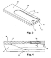
- Figs. 3 and 4 illustrate another manner of releasing a blister card which is held by a dispenser in which it is held by the guides (preferably In the bent shape) 14, and which Is biased between the bottom of the slot 12 and the element 16.
- the release is obtained by moving the element 16 toward the bottom of the slot 12, whereby the blister card Is further compressed and will attempt to bulge out.
- the guides 14 will make the blister card maintain its shape along the length of the dispenser but a predetermined length at the opening 10, where the blister card Is allowed to bulge out due to the further compression. This bulging out (which is here only possible to one side) will eventually make the blister card end move over the element 16, whereby the blister card is released.
- the element 16 Is mounted so as to be displaceable in the longitudinal direction of the dispenser.
- the element 16 is biased away from the centre of the dispenser by one or more torsion springs 34, but Is movable, by exerting a predetermined force, toward the centre of the dispenser In order to release the blister card.
- Figs. 5 and 6 illustrate a different embodiment, which, again, comprises the opening 10, the slot 12, the guides 14 (but which are not illustrated), the upper and lower parts 18 and 20 as well as the opening 20'.
- the engagement of the blister card is obtained by two leaf springs 50, one positioned at each longitudinal side of the blister card - but where only one is illustrated.
- leaf springs are attached, at one end, 50', to the upper part 18 of the dispenser by e.g. weldings 52.
- the leaf springs are shaped so as to bias the other end, 50", toward the blister card. Removal of the blister card is in the right direction of the Figures, whereby it is seen that the leaf springs 50 will tighten the engagement even further and block the movement of the blister card. Insertion, however, of the blister card meets no substantial friction with the leaf springs 50.
- the member 54 is biased toward a right-most (in the figure) position so as to only release the blister card when a force is applied to the member 54.
- the sliding in the direction of the plane of the blister card (or at least at the longitudinal position at which the sliding means are positioned, when the blister card is not straight) is more difficult for children to see or deduce. This is especially true, when two such operations are required in order to release the blister card.
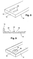
- Fig. 7 illustrates another manner of providing the displaceable member 30 in the embodiment of Fig. 1 .
- This manner comprises a displaceable member 60 which is not "embedded” in a softer plastic material but is simply cut out or moulded with the remaining part of the upper part 18.
- Fig. 8 is a further alternative, where the displaceable member 62 is made displaceable by providing two elongate slots 64, which make the member 62 more easily displaced toward the blister card.
- Fig. 9 the softer material 32 in Fig. 1 is replaced by a part 66 which is thinner than the surrounding parts of the upper part 18.
- the displaceable element, 64 is displaceable in order to have the blister card end move over the part 16.
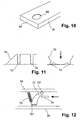
- Fig. 10 illustrates yet another manner, which may be found to be efficient and cheap but less child resistant.
- An opening or hole 68 is provided for inserting a finger or a tool (pencil or the like) for displacing the blister card over the member 16.
- Fig. 11 illustrates a manner alternative to that of Fig. 3 for providing an engagement and a release thereof using a leaf spring.
- the leaf spring 70 forms part of a deformable element having two studs 72 which are adapted to engage the dispenser or the blister card.
- a deformation will occur due to the abutment of the studs 72, whereby the leaf spring will be lifted from the blister card and the blister card released.
- the user may engage the element via push buttons at the outer side of the dispenser - or directly via e.g. a hole - or the element may be integrated in the dispenser.
- Fig. 12 illustrates an embodiment where the leaf spring 50 is replaced by a rotatable element 70 rotatably attached to the part 18 and rotatable around an axis 70'.
- the element 70 is biased against the blister card by a spring 72, and is adapted to be lifted there from by a slidable element 74 which is translated in the direction of the arrow, whereby the element 70 will disengage the blister card.
- the direction of insertion of the blister card is in the direction from right to left, whereby it is seen that unauthorized removal of the blister card will make the element 70 engage even more with the blister card.
- the element 70 is illustrated with a number of edges or peaks 70"' which are adapted to provide a sufficient friction with the blister card.
- FIG. 13 an element 80 with an operation similar to that of Fig. 12 is seen (rotatably mounted and rotatable around an axis 80'). However, in this embodiment, the element 80 abuts and engages a blister 82' of the blister card 84. Again, a slideable element 82 releases the engagement. Thus, lower requirements as to the friction and other engagements is obtained in that removal of this blister card will require deformation of the blister - and then some.
- Fig. 14 illustrates an embodiment with a functionality close to that of Fig. 3 , but where the blister card is deformed around the longitudinal axis by two push buttons 84. This deformation will displace the central portion of the blister card, whereby disengagement may be obtained with any of the above engaging means.
- Fig. 15 finally, illustrates that at the bottom of the slot 12 of the dispenser, a spring or other resilient means may be provided.
- This spring/means 90 is biased when the blister card 92 is inserted and will act to push the card outwardly, when the engaging means are released.
Landscapes
- Engineering & Computer Science (AREA)
- Mechanical Engineering (AREA)
- Packages (AREA)
- Containers And Packaging Bodies Having A Special Means To Remove Contents (AREA)
- Toys (AREA)
Claims (54)
- Un distributeur destiné à soutenir un moyen de support (92) pour distribution d'unités,- le moyen de support (92) comprenant une pluralité d'unités devant être distribuées depuis une surface prédéterminée de celui-ci,- le distributeur comprenant :caractérisé en ce que :o une ouverture (10) destinée à recevoir le moyen de support,o des moyens (20) empêchant l'accès aux unités depuis la surface prédéterminée lorsque le moyen de support est reçu par le distributeur,o des moyens (14, 16) permettant d'engager le moyen de support (92) lorsque le moyen de support (92) est reçu par le distributeur,o des moyens permettant de libérer les moyens d'engagement, eto des moyens (14) destinés à maintenir la surface prédéterminée sur ou dans un plan prédéterminé lorsque le moyen de support (92) est reçu par le distributeur,- le moyen d'engagement comprend des moyens (16) permettant de faire venir en butée une partie de bord du moyen de support faisant face à l'ouverture (10) lorsque le moyen de support (92) est reçu dans l'ouverture (10), le moyen de butée (16) ayant une surface de butée (16') faisant face à la partie de bord du moyen de support (92), s'étendant de façon à former un angle avec le plan prédéterminé et à une distance prédéterminée du plan, et- le moyen de libération comprend des moyens (16, 30, 60, 62, 64) permettant de déplacer la partie de bord du moyen de support à l'écart du plan au moins de la distance prédéterminée.
- Un distributeur selon la revendication 1, dans lequel le moyen de maintien permet de solliciter le moyen de support contre une ou plusieurs parties de surface du distributeur, la (les) partie(s) de surface définissant le plan prédéterminé.
- Un distributeur selon la revendication 2, dans lequel la partie de bord de butée s'étend à l'écart de la (des) partie(s) de surface de la distance prédéterminée.
- Un distributeur selon la revendication 2 ou la revendication 3, dans lequel le moyen de déplacement permet de déplacer la partie de bord au moins de la distance prédéterminée à l'écart de la (des) partie(s) de surface.
- Un distributeur selon l'une quelconque des revendications précédentes, le moyen de déplacement étant agencé dans une partie du distributeur définissant également la (les) partie(s) de surface, le moyen de déplacement permettant de déplacer la partie de bord dans une direction formant un angle avec le plan prédéterminé.
- Un distributeur selon la revendication 5, dans lequel le moyen de déplacement peut être engagé par un utilisateur depuis une ou plusieurs des parties de surface externe du distributeur.
- Un distributeur selon la revendication 6, le distributeur comprenant, à l'emplacement de la partie de surface externe et dans la (les) partie(s) du distributeur définissant la (les) partie(s) de surface, un élément élastique ou déformable pouvant être déformé ou déplacé par l'utilisateur afin de déplacer la partie de bord du moyen de support.
- Un distributeur selon l'une quelconque des revendications 2 à 7, dans lequel la (les) partie(s) de surface prédéterminée(s) du moyen de support est (sont) prévue(s) pour faire face à (aux) partie(s) de surface
- Un distributeur selon l'une quelconque des revendications 2 à 8, dans lequel la partie de bord du moyen de support est une partie de bord externe du moyen de support.
- Un distributeur selon l'une quelconque des revendications 2 a 9, dans lequel le moyen d'engagement est déplaçable selon une direction située au moins sensiblement le long du plan prédétermine, le distributeur comprenant des moyens permettant à une partie du moyen de support adjacente de la partie de bord de se courber à l'écart du plan prédéterminé suite à la sollicitation.
- Un distributeur selon l'une quelconque des revendications précédentes, dans lequel le plan prédéterminé a une forme incurvée.
- Un procédé de fonctionnement d'un distributeur destiné à soutenir un moyen de support pour distribution d'unités,- le moyen de support (92) comprenant une pluralité d'unités devant être distribuées depuis une surface prédéterminée de celui-ci,- le distributeur comprenant :caractérisé en ce que le procédé comprend en outre les étapes suivantes:o une ouverture (10) destinée à recevoir le moyen de support,o des moyens (20) empêchant l'accès aux unités depuis la surface prédéterminée lorsque le moyen de support est reçu par le distributeur,o des moyens (14, 16) permettant d'engager le moyen de support (92) lorsque le moyen de support (92) est reçu par le distributeur, eto des moyens permettant de libérer les moyens d'engagement,le procédé comprenant l'étape de maintien de la première surface sur ou dans un plan prédéterminé lorsque le moyen de support est reçu par le distributeur,- faire venir en butée une partie de bord du moyen de support (92) faisant face à l'ouverture (10) lorsque le moyen de support (92) est reçu dans l'ouverture (10), le moyen de butée (16) ayant une surface de butée (16') faisant face à la partie de bord du moyen de support (92), s'étendant de façon à former un angle avec le plan prédéterminé et à une distance prédéterminée du plan, et- une étape de libération comprenant le déplacement de la partie de bord du moyen de support (92) à l'écart du plan au moins de la distance prédéterminée
- Un procédé selon la revendication 12, dans lequel l'étape de maintien comprend la sollicitation du moyen de support contre une ou plusieurs parties de surface du distributeur, la (les) partie(s) de surface définissant le plan prédéterminé.
- Un procédé selon la revendication 13, dans lequel la partie de bord de butée s'étend à l'écart de la (des) partie(s) de surface de la distance prédéterminée.
- Un procédé selon la revendication 13 ou la revendication 14, dans lequel l'étape de déplacement comprend le déplacement de la partie de bord au moins de la distance prédéterminée à l'écart de la (des) partie(s) de surface.
- Un procédé selon la revendication 13, la revendication 14 ou la revendication 15, dans lequel les moyens de déplacement sont agencés dans une partie du distributeur définissant également la (les) partie(s) de surface, l'étape de déplacement comprenant le déplacement de la partie de bord dans une direction formant un angle avec le plan prédéterminé.
- Un procédé selon la revendication 16, dans lequel l'étape de déplacement implique un utilisateur réalisant le déplacement depuis une partie de surface externe du distributeur.
- Un procédé selon la revendication 17, dans lequel le déplacement est réalisé par l'utilisateur déformant ou déplaçant la partie d'extrémité du moyen de support en déformant ou en déplaçant un élément élastique ou déformable prévu dans la partie du distributeur définissant la (les) partie(s) de surface.
- Un procédé selon l'une quelconque des revendications 13 à 18, dans lequel la partie de surface prédéterminée du moyen de support fait face à (aux) partie(s) de surface.
- Un procédé selon l'une quelconque des revendications 13 à 19, dans lequel la partie de bord du moyen de support est une partie de bord externe du moyen de support
- Un procédé selon l'une quelconque des revendications 13 à 20, dans lequel les moyens d'engagement sont déplaces selon une direction située au moins sensiblement le long du plan prédeterminé, de telle façon qu'une partie du moyen de support adjacente de la partie de bord se courbe à l'écart du plan prédéterminé suite à la sollicitation
- Un procédé selon l'une quelconque des revendications 12 à 21, dans lequel le plan prédéterminé a une forme incurvée.
- Un distributeur destiné à soutenir un moyen de support (92) pour distribution d'unités,- le moyen de support (92) comprenant une pluralité d'unités devant être distribuées depuis une surface prédéterminée de celui-ci,- le distributeur comprenant :caractérisé en ce que les moyens d'engagement comprennent des moyens de sollicitation pouvant être libérés (50, 70, 80) destinés à exercer une force de friction sur une surface du moyen de support afin d'empêcher ou de rendre difficile le retrait de celui-ci du distributeur.o une fente (12) ayant une ouverture destinée à recevoir le moyen de support,o des moyens (20) empêchant l'accès aux unités depuis la surface prédéterminée lorsque le moyen de support (92) est reçu dans la fente,o des moyens permettant d'engager le moyen de support (92) lorsque le moyen de support (92) est reçu dans la fente (12), eto des moyens (54, 75, 82) permettant de libérer les moyens d'engagement,
- Un distributeur selon la revendication 23, dans lequel le moyen de sollicitation pouvant être libéré peut exercer un première friction lors du mouvement du moyen de support dans le distributeur et une seconde friction plus importante lors du retrait du moyen de support du distributeur, lorsque le moyen de libération n'est pas actionné.
- Un distributeur selon la revendication 24, dans lequel le moyen de libération permet au moyen de sollicitation d'exercer une troisième friction lors du retrait du moyen de support du distributeur, lorsque le moyen de libération est actionné, la troisième friction étant plus faible que la seconde friction.
- Un distributeur selon l'une quelconque des revendications 23 a 25, dans lequel le moyen de sollicitation pouvant être libéré comprend au moins un ressort à lames ayant deux extrémités, l'une des extrémités venant au contact du distributeur et l'autre extrémité étant agencée de façon a venir au contact du moyen de support lorsque celui-ci est reçu dans le distributeur, le ressort étant agencé de façon que la première des extrémités soit positionnée plus près de l'ouverture que l'autre extrémité.
- Un distributeur selon la revendication 26, l'au moins un ressort à lames ayant une direction longitudinale située entre la première extrémité et l'autre extrémité, la direction longitudinale étant au moins sensiblement parallèle à une direction de mouvement du moyen de support lors de la réception dans la fente.
- Un distributeur selon l'une quelconque des revendications 26 ou 27, dans lequel le moyen de libération peut mettre hors de contact le ressort à lames et le moyen de support.
- Un distributeur selon la revendication 28, dans lequel les moyens de libération peuvent déplacer l'autre extrémité du ressort à lames dans une direction à l'écart du moyen de support.
- Un distributeur selon la revendication 29, dans lequel le moyen de libération peut subir une translation selon une direction longitudinale du ressort, le moyen de libération ayant des moyens permettant d'engager le ressort et de maintenir au moins une partie du ressort à l'écart du moyen de support.
- Un distributeur selon l'une quelconque des revendications 23 à 30, dans lequel le moyen de sollicitation pouvant être libéré comprend un élément pouvant pivoter autour d'un axe prédéterminé et ayant une partie pouvant exercer la force de friction lorsque l'élément est pivoté dans une première position, le moyen de libération étant prévu pour faire pivoter l'élément vers une seconde position dans laquelle une friction plus faible est exercée par l'élément
- Un distributeur selon la revendication 31, dans lequel le moyen de sollicitation pouvant être libéré comprend en outre des moyens pour solliciter l'élément en direction du moyen de support lorsque l'élément est dans la première position
- Un distributeur selon la revendication 31 ou la revendication 32, dans lequel l'élément comprend une ou plusieurs parties de bord prévues pour venir au contact du moyen de support lorsque l'élément est dans la première position.
- Un distributeur selon l'une quelconque des revendications 31 à 33, dans lequel l'axe prédéterminé est au moins sensiblement perpendiculaire à une direction de mouvement du moyen de support lors de la réception dans la fente.
- Un distributeur selon la revendication 34, dans lequel l'axe de rotation est positionné plus près de l'ouverture que la partie pouvant exercer la friction.
- Un procédé de fonctionnement d'un distributeur destiné à soutenir un moyen support (92) pour distribution d'unités,- le moyen de support (92) comprenant une pluralité d'unités devant être distribuées depuis une surface prédéterminée de celui-ci,- le distributeur comprenant :caractérisé en ce que le procédé comprend l'étape consistant à faire exercer une force de friction par un moyen de sollicitation pouvant être libéré du moyen d'engagement (50, 70, 80) sur une surface du moyen de support (92) afin d'empêcher ou de rendre difficile le retrait de celui-ci du distributeuro une fente (12) ayant une ouverture (10) destinée à recevoir le moyen de support (92),o des moyens (20) empêchant l'accès aux unités depuis la surface prédéterminée lorsque le moyen de support (92) est reçu dans la fente (12),o des moyens permettant d'engager le moyen de support (92) lorsque le moyen de support (92) est reçu dans la fente (12), eto des moyens (54, 75, 82) permettant de libérer les moyens d'engagement,
- Un procédé selon la revendication 36, dans lequel le moyen de sollicitation pouvant être libéré exerce une première friction lors du mouvement du moyen de support dans le distributeur et une seconde friction plus forte lors du retrait du moyen de support du distributeur, lorsque le moyen de libération n'est pas actionné
- Un procédé selon la revendication 37, dans lequel le moyen de sollicitation exerce une troisième friction lors du retrait du moyen de support du distributeur, lorsque le moyen de libération est actionné, la troisième friction étant plus faible que la seconde friction.
- Un procédé selon l'une quelconque des revendications 36 à 38, dans lequel le moyen de sollicitation pouvant être libéré comprend au moins un ressort à lames ayant deux extrémités, l'une des extrémités venant au contact du distributeur et l'autre extrémité venant au contact du moyen de support lorsque celui-ci est reçu dans le distributeur, le ressort étant agencé de façon que la première des extrémités soit positionnée plus près de l'ouverture que l'autre extrémité.
- Un procédé selon la revendication 39, l'au moins un ressort à lames ayant une direction longitudinale située entre la première extrémité et l'autre extrémité, la direction longitudinale étant au moins sensiblement parallèle à une direction de mouvement du moyen de support lors de la réception dans la fente.
- Un procédé selon l'une quelconque des revendications 39 ou 40, comprenant en outre une étape de libération dans laquelle le moyen de libération peut mettre hors de contact le ressort à lames et le moyen de support.
- Un procédé selon la revendication 41, dans lequel les moyens de libération déplacent l'autre extrémité du ressort à lames dans une direction à l'écart du moyen de support.
- Un procédé selon la revendication 42, dans lequel les moyens de libération subissent une translation selon une direction longitudinale du ressort, les moyens de libération ayant des moyens permettant d'engager le ressort et de maintenir au moins une partie du ressort à l'écart du moyen de support.
- Un procédé selon l'une quelconque des revendications 36 à 43, dans lequel les moyens de sollicitation pouvant être libérés sont pivotés autour d'un axe prédéterminé et ont une partie exerçant la force de friction lorsque l'élément est pivoté dans une première position, le moyen de libération faisant pivoter l'élément vers une seconde position dans laquelle une friction plus faible est exercée par l'élément.
- Un procédé selon la revendication 44, dans lequel le moyen de sollicitation pouvant être libéré comprend en outre des moyens pour solliciter l'élément en direction du moyen de support lorsque l'élément est dans la première position.
- Un procédé selon la revendication 44 ou la revendication 45, dans lequel l'étape d'engagement comprend la mise en contact d'une ou plusieurs parties de bord du moyen de sollicitation pouvant être libéré avec le moyen de support lorsque l'élément est dans la première position.
- Un procédé selon l'une quelconque des revendications 44 à 46, dans lequel la rotation est effectuée autour d'un axe prédéterminé qui est au moins sensiblement perpendiculaire à une direction de mouvement du moyen de support lors de la réception dans la fente.
- Un procédé selon la revendication 47, dans lequel l'axe de rotation est positionné plus près de l'ouverture que la partie pouvant exercer la friction.
- Un distributeur selon l'une quelconque des revendications 1 à 11 ou 23 à 35, comprenant en outre un moyen de sollicitation pouvant être sollicité par le moyen de support lorsque celui-ci est reçu dans la fente et qui peut déplacer le moyen de support dans une direction extérieure à la fente lorsque les moyens de libération sont actionnés.
- Un distributeur selon l'une quelconque des revendications 1 à 11 ou 23 à 35, dans lequel le moyen de libération comprend un ou plusieurs boutons-poussoirs, le fait de pousser l'un ou plusieurs des boutons vers ou dans le distributeur libérant les moyens d'engagement ou de sollicitation
- Un distributeur selon l'une quelconque des revendications 1 a 11 ou 23 a 35, dans lequel le moyen de libération comprend un ou plusieurs éléments pouvant pivoter, la rotation de l'élément (des éléments) pouvant pivoter libérant les moyens d'engagement ou de sollicitation.
- Un procédé selon l'une quelconque des revendications 12 à 22 ou 36 à 48, comprenant en outre l'étape de sollicitation d'un moyen de sollicitation lors de l'insertion du moyen de support dans la fente, une étape de sortie comprenant l'étape de sollicitation comprenant l'étape de poussée du moyen de support dans une direction extérieure à la fente par les moyens de sollicitation, suite à l'actionnement des moyens de libération.
- Un procédé selon l'une quelconque des revendications 12 à 22 ou 36 à 48, dans lequel l'étape de libération comprend le fait de pousser un ou plusieurs boutons vers ou dans le distributeur afin de libérer les moyens d'engagement ou de sollicitation.
- Un procédé selon l'une quelconque des revendications 12 à 22 ou 36 à 48, dans lequel l'étape de libération comprend la rotation d'un ou plusieurs éléments pouvant pivoter afin de libérer les moyens d'engagement ou de sollicitation.
Applications Claiming Priority (2)
| Application Number | Priority Date | Filing Date | Title |
|---|---|---|---|
| US47550503P | 2003-06-04 | 2003-06-04 | |
| PCT/DK2004/000383 WO2004108562A1 (fr) | 2003-06-04 | 2004-06-03 | Distributeur de support, par exemple, d'une bande alveolaire thermoformee |
Publications (2)
| Publication Number | Publication Date |
|---|---|
| EP1633656A1 EP1633656A1 (fr) | 2006-03-15 |
| EP1633656B1 true EP1633656B1 (fr) | 2008-08-13 |
Family
ID=33511686
Family Applications (1)
| Application Number | Title | Priority Date | Filing Date |
|---|---|---|---|
| EP04735872A Expired - Lifetime EP1633656B1 (fr) | 2003-06-04 | 2004-06-03 | Distributeur de support, par exemple, d'une bande alveolaire thermoformee |
Country Status (5)
| Country | Link |
|---|---|
| US (1) | US20070272585A1 (fr) |
| EP (1) | EP1633656B1 (fr) |
| AT (1) | ATE404459T1 (fr) |
| DE (1) | DE602004015785D1 (fr) |
| WO (1) | WO2004108562A1 (fr) |
Families Citing this family (2)
| Publication number | Priority date | Publication date | Assignee | Title |
|---|---|---|---|---|
| US7607538B2 (en) * | 2007-08-27 | 2009-10-27 | Schering-Plough Healthcare Products, Inc. | Container for transporting a blister package |
| US20190289990A1 (en) * | 2018-03-23 | 2019-09-26 | Eddie Dutchover | Narholder device |
Family Cites Families (6)
| Publication number | Priority date | Publication date | Assignee | Title |
|---|---|---|---|---|
| CH523181A (de) * | 1970-05-04 | 1972-05-31 | Hoffmann La Roche | Durchdrückpackung |
| US4120400A (en) * | 1976-11-22 | 1978-10-17 | Primary Design Group, Inc. | Pill package |
| US6155454A (en) * | 1997-05-03 | 2000-12-05 | Donald C. George | Pill dispenser employing a sealed pill carrier and integrated dispensing plungers |
| US6047829A (en) * | 1998-09-18 | 2000-04-11 | Westvaco Corporation | Unit dose packaging system (UDPS) having a child resistant locking feature |
| US6460693B1 (en) * | 1999-05-19 | 2002-10-08 | Valley Design, Inc. | Child resistant blister pack container with compound action release mechanism |
| US6752272B2 (en) * | 2001-09-13 | 2004-06-22 | Mead Westvaco Corporation | Unit dose packaging system with exterior pocket feature |
-
2004
- 2004-06-03 EP EP04735872A patent/EP1633656B1/fr not_active Expired - Lifetime
- 2004-06-03 DE DE602004015785T patent/DE602004015785D1/de not_active Expired - Fee Related
- 2004-06-03 AT AT04735872T patent/ATE404459T1/de not_active IP Right Cessation
- 2004-06-03 WO PCT/DK2004/000383 patent/WO2004108562A1/fr not_active Ceased
- 2004-06-03 US US10/559,613 patent/US20070272585A1/en not_active Abandoned
Also Published As
| Publication number | Publication date |
|---|---|
| EP1633656A1 (fr) | 2006-03-15 |
| DE602004015785D1 (fr) | 2008-09-25 |
| ATE404459T1 (de) | 2008-08-15 |
| WO2004108562A1 (fr) | 2004-12-16 |
| US20070272585A1 (en) | 2007-11-29 |
Similar Documents
| Publication | Publication Date | Title |
|---|---|---|
| US7798329B2 (en) | Insert package | |
| EP1480897B1 (fr) | Dispositif de plaquette alveolaire | |
| EP2262702B1 (fr) | Récipient pour médicaments à l'épreuve des enfants | |
| US5931302A (en) | Pellet dispenser | |
| JP3422774B2 (ja) | ブリスターパック保持装置 | |
| EP1896101B1 (fr) | Inhalateur avec un indicateur de défauts | |
| US20210196574A1 (en) | Pill dispenser | |
| AU2006316035B2 (en) | A blister pack device and a method of ejecting a unit dosage from a blister pack using the device. | |
| US20060006091A1 (en) | Child-resistant container | |
| US8550249B2 (en) | Medicament dispenser and method | |
| CA2580337A1 (fr) | Contenant a l'epreuve des enfants | |
| MX2013005879A (es) | Inhalador. | |
| CN103979125A (zh) | 药片盒 | |
| WO2007070867A2 (fr) | Distributeur a securite pour enfants | |
| WO2021263242A1 (fr) | Dispositif de distribution de consommables | |
| JP6266014B2 (ja) | カウンタ | |
| EP1633656B1 (fr) | Distributeur de support, par exemple, d'une bande alveolaire thermoformee | |
| EP1935807A1 (fr) | Emballage pour médicaments | |
| JP5130873B2 (ja) | 自動販売機の商品収納装置 | |
| EP2119639A1 (fr) | Mécanisme de déclenchement pour calendrier de pilule | |
| US8291900B2 (en) | Blister assembly for inhalation device | |
| CN203512512U (zh) | 泡罩包装药剂发放箱 | |
| US20060005398A1 (en) | Device for removing a pharmaceutical dosage unit from a unit package | |
| WO2024143506A1 (fr) | Cassette de médicament | |
| JP3109860U (ja) | 名刺入れ |
Legal Events
| Date | Code | Title | Description |
|---|---|---|---|
| PUAI | Public reference made under article 153(3) epc to a published international application that has entered the european phase |
Free format text: ORIGINAL CODE: 0009012 |
|
| 17P | Request for examination filed |
Effective date: 20060104 |
|
| AK | Designated contracting states |
Kind code of ref document: A1 Designated state(s): AT BE BG CH CY CZ DE DK EE ES FI FR GB GR HU IE IT LI LU MC NL PL PT RO SE SI SK TR |
|
| DAX | Request for extension of the european patent (deleted) | ||
| RIN1 | Information on inventor provided before grant (corrected) |
Inventor name: JOHANSEN, ESBEN, W. Inventor name: FABRICIUS, PAUL, ERIK Inventor name: FALK KNUDSEN, LARS |
|
| GRAP | Despatch of communication of intention to grant a patent |
Free format text: ORIGINAL CODE: EPIDOSNIGR1 |
|
| GRAS | Grant fee paid |
Free format text: ORIGINAL CODE: EPIDOSNIGR3 |
|
| GRAA | (expected) grant |
Free format text: ORIGINAL CODE: 0009210 |
|
| AK | Designated contracting states |
Kind code of ref document: B1 Designated state(s): AT BE BG CH CY CZ DE DK EE ES FI FR GB GR HU IE IT LI LU MC NL PL PT RO SE SI SK TR |
|
| REG | Reference to a national code |
Ref country code: GB Ref legal event code: FG4D |
|
| REG | Reference to a national code |
Ref country code: CH Ref legal event code: EP |
|
| REG | Reference to a national code |
Ref country code: IE Ref legal event code: FG4D |
|
| REF | Corresponds to: |
Ref document number: 602004015785 Country of ref document: DE Date of ref document: 20080925 Kind code of ref document: P |
|
| PG25 | Lapsed in a contracting state [announced via postgrant information from national office to epo] |
Ref country code: NL Free format text: LAPSE BECAUSE OF FAILURE TO SUBMIT A TRANSLATION OF THE DESCRIPTION OR TO PAY THE FEE WITHIN THE PRESCRIBED TIME-LIMIT Effective date: 20080813 Ref country code: ES Free format text: LAPSE BECAUSE OF FAILURE TO SUBMIT A TRANSLATION OF THE DESCRIPTION OR TO PAY THE FEE WITHIN THE PRESCRIBED TIME-LIMIT Effective date: 20081124 |
|
| PG25 | Lapsed in a contracting state [announced via postgrant information from national office to epo] |
Ref country code: AT Free format text: LAPSE BECAUSE OF FAILURE TO SUBMIT A TRANSLATION OF THE DESCRIPTION OR TO PAY THE FEE WITHIN THE PRESCRIBED TIME-LIMIT Effective date: 20080813 Ref country code: FI Free format text: LAPSE BECAUSE OF FAILURE TO SUBMIT A TRANSLATION OF THE DESCRIPTION OR TO PAY THE FEE WITHIN THE PRESCRIBED TIME-LIMIT Effective date: 20080813 Ref country code: SI Free format text: LAPSE BECAUSE OF FAILURE TO SUBMIT A TRANSLATION OF THE DESCRIPTION OR TO PAY THE FEE WITHIN THE PRESCRIBED TIME-LIMIT Effective date: 20080813 |
|
| PG25 | Lapsed in a contracting state [announced via postgrant information from national office to epo] |
Ref country code: BE Free format text: LAPSE BECAUSE OF FAILURE TO SUBMIT A TRANSLATION OF THE DESCRIPTION OR TO PAY THE FEE WITHIN THE PRESCRIBED TIME-LIMIT Effective date: 20080813 |
|
| PG25 | Lapsed in a contracting state [announced via postgrant information from national office to epo] |
Ref country code: DK Free format text: LAPSE BECAUSE OF FAILURE TO SUBMIT A TRANSLATION OF THE DESCRIPTION OR TO PAY THE FEE WITHIN THE PRESCRIBED TIME-LIMIT Effective date: 20080813 Ref country code: BG Free format text: LAPSE BECAUSE OF FAILURE TO SUBMIT A TRANSLATION OF THE DESCRIPTION OR TO PAY THE FEE WITHIN THE PRESCRIBED TIME-LIMIT Effective date: 20081113 |
|
| PG25 | Lapsed in a contracting state [announced via postgrant information from national office to epo] |
Ref country code: SK Free format text: LAPSE BECAUSE OF FAILURE TO SUBMIT A TRANSLATION OF THE DESCRIPTION OR TO PAY THE FEE WITHIN THE PRESCRIBED TIME-LIMIT Effective date: 20080813 Ref country code: PT Free format text: LAPSE BECAUSE OF FAILURE TO SUBMIT A TRANSLATION OF THE DESCRIPTION OR TO PAY THE FEE WITHIN THE PRESCRIBED TIME-LIMIT Effective date: 20090113 Ref country code: RO Free format text: LAPSE BECAUSE OF FAILURE TO SUBMIT A TRANSLATION OF THE DESCRIPTION OR TO PAY THE FEE WITHIN THE PRESCRIBED TIME-LIMIT Effective date: 20080813 Ref country code: CZ Free format text: LAPSE BECAUSE OF FAILURE TO SUBMIT A TRANSLATION OF THE DESCRIPTION OR TO PAY THE FEE WITHIN THE PRESCRIBED TIME-LIMIT Effective date: 20080813 |
|
| PLBE | No opposition filed within time limit |
Free format text: ORIGINAL CODE: 0009261 |
|
| STAA | Information on the status of an ep patent application or granted ep patent |
Free format text: STATUS: NO OPPOSITION FILED WITHIN TIME LIMIT |
|
| 26N | No opposition filed |
Effective date: 20090514 |
|
| PG25 | Lapsed in a contracting state [announced via postgrant information from national office to epo] |
Ref country code: EE Free format text: LAPSE BECAUSE OF FAILURE TO SUBMIT A TRANSLATION OF THE DESCRIPTION OR TO PAY THE FEE WITHIN THE PRESCRIBED TIME-LIMIT Effective date: 20080813 |
|
| PG25 | Lapsed in a contracting state [announced via postgrant information from national office to epo] |
Ref country code: IT Free format text: LAPSE BECAUSE OF FAILURE TO SUBMIT A TRANSLATION OF THE DESCRIPTION OR TO PAY THE FEE WITHIN THE PRESCRIBED TIME-LIMIT Effective date: 20080813 |
|
| PG25 | Lapsed in a contracting state [announced via postgrant information from national office to epo] |
Ref country code: MC Free format text: LAPSE BECAUSE OF NON-PAYMENT OF DUE FEES Effective date: 20090630 Ref country code: SE Free format text: LAPSE BECAUSE OF FAILURE TO SUBMIT A TRANSLATION OF THE DESCRIPTION OR TO PAY THE FEE WITHIN THE PRESCRIBED TIME-LIMIT Effective date: 20081113 |
|
| REG | Reference to a national code |
Ref country code: CH Ref legal event code: PL |
|
| GBPC | Gb: european patent ceased through non-payment of renewal fee |
Effective date: 20090603 |
|
| REG | Reference to a national code |
Ref country code: FR Ref legal event code: ST Effective date: 20100226 |
|
| PG25 | Lapsed in a contracting state [announced via postgrant information from national office to epo] |
Ref country code: FR Free format text: LAPSE BECAUSE OF NON-PAYMENT OF DUE FEES Effective date: 20090630 Ref country code: CH Free format text: LAPSE BECAUSE OF NON-PAYMENT OF DUE FEES Effective date: 20090630 Ref country code: LI Free format text: LAPSE BECAUSE OF NON-PAYMENT OF DUE FEES Effective date: 20090630 Ref country code: IE Free format text: LAPSE BECAUSE OF NON-PAYMENT OF DUE FEES Effective date: 20090603 |
|
| PG25 | Lapsed in a contracting state [announced via postgrant information from national office to epo] |
Ref country code: PL Free format text: LAPSE BECAUSE OF FAILURE TO SUBMIT A TRANSLATION OF THE DESCRIPTION OR TO PAY THE FEE WITHIN THE PRESCRIBED TIME-LIMIT Effective date: 20080813 Ref country code: GB Free format text: LAPSE BECAUSE OF NON-PAYMENT OF DUE FEES Effective date: 20090603 |
|
| PG25 | Lapsed in a contracting state [announced via postgrant information from national office to epo] |
Ref country code: DE Free format text: LAPSE BECAUSE OF NON-PAYMENT OF DUE FEES Effective date: 20100101 |
|
| PG25 | Lapsed in a contracting state [announced via postgrant information from national office to epo] |
Ref country code: GR Free format text: LAPSE BECAUSE OF FAILURE TO SUBMIT A TRANSLATION OF THE DESCRIPTION OR TO PAY THE FEE WITHIN THE PRESCRIBED TIME-LIMIT Effective date: 20081114 |
|
| PG25 | Lapsed in a contracting state [announced via postgrant information from national office to epo] |
Ref country code: LU Free format text: LAPSE BECAUSE OF NON-PAYMENT OF DUE FEES Effective date: 20090603 |
|
| PG25 | Lapsed in a contracting state [announced via postgrant information from national office to epo] |
Ref country code: HU Free format text: LAPSE BECAUSE OF FAILURE TO SUBMIT A TRANSLATION OF THE DESCRIPTION OR TO PAY THE FEE WITHIN THE PRESCRIBED TIME-LIMIT Effective date: 20090214 |
|
| PG25 | Lapsed in a contracting state [announced via postgrant information from national office to epo] |
Ref country code: TR Free format text: LAPSE BECAUSE OF FAILURE TO SUBMIT A TRANSLATION OF THE DESCRIPTION OR TO PAY THE FEE WITHIN THE PRESCRIBED TIME-LIMIT Effective date: 20080813 |
|
| PG25 | Lapsed in a contracting state [announced via postgrant information from national office to epo] |
Ref country code: CY Free format text: LAPSE BECAUSE OF FAILURE TO SUBMIT A TRANSLATION OF THE DESCRIPTION OR TO PAY THE FEE WITHIN THE PRESCRIBED TIME-LIMIT Effective date: 20080813 |