EP1634032B1 - Verbesserte feuerwaffe - Google Patents
Verbesserte feuerwaffe Download PDFInfo
- Publication number
- EP1634032B1 EP1634032B1 EP04734328A EP04734328A EP1634032B1 EP 1634032 B1 EP1634032 B1 EP 1634032B1 EP 04734328 A EP04734328 A EP 04734328A EP 04734328 A EP04734328 A EP 04734328A EP 1634032 B1 EP1634032 B1 EP 1634032B1
- Authority
- EP
- European Patent Office
- Prior art keywords
- sear
- trigger
- link
- cross
- bar
- Prior art date
- Legal status (The legal status is an assumption and is not a legal conclusion. Google has not performed a legal analysis and makes no representation as to the accuracy of the status listed.)
- Expired - Lifetime
Links
- 238000007599 discharging Methods 0.000 claims abstract description 4
- 238000010304 firing Methods 0.000 claims description 18
- 238000004880 explosion Methods 0.000 claims description 8
- 230000007246 mechanism Effects 0.000 claims description 8
- 230000000295 complement effect Effects 0.000 claims 1
- 230000035945 sensitivity Effects 0.000 abstract description 13
- 230000006835 compression Effects 0.000 description 3
- 238000007906 compression Methods 0.000 description 3
- 230000003247 decreasing effect Effects 0.000 description 3
- 230000000694 effects Effects 0.000 description 3
- 238000000034 method Methods 0.000 description 2
- 210000000707 wrist Anatomy 0.000 description 2
- 230000000903 blocking effect Effects 0.000 description 1
- 238000010586 diagram Methods 0.000 description 1
- 230000007613 environmental effect Effects 0.000 description 1
- 230000001105 regulatory effect Effects 0.000 description 1
- 210000000515 tooth Anatomy 0.000 description 1
Images


Classifications
-
- F—MECHANICAL ENGINEERING; LIGHTING; HEATING; WEAPONS; BLASTING
- F41—WEAPONS
- F41A—FUNCTIONAL FEATURES OR DETAILS COMMON TO BOTH SMALLARMS AND ORDNANCE, e.g. CANNONS; MOUNTINGS FOR SMALLARMS OR ORDNANCE
- F41A19/00—Firing or trigger mechanisms; Cocking mechanisms
- F41A19/06—Mechanical firing mechanisms, e.g. counterrecoil firing, recoil actuated firing mechanisms
- F41A19/42—Mechanical firing mechanisms, e.g. counterrecoil firing, recoil actuated firing mechanisms having at least one hammer
- F41A19/43—Mechanical firing mechanisms, e.g. counterrecoil firing, recoil actuated firing mechanisms having at least one hammer in bolt-action guns
- F41A19/44—Sear arrangements therefor
Definitions
- This invention relates to an improved firearm, particularly to a new and improved trigger assembly that may be adjusted during assembly and during use to provide a sensitivity adjustment for a firearm, and more particularly to a new and improved trigger assembly for a convertible firearm.
- Firearms are mostly utilized by law enforcement, sport enthusiasts and private owners for target, game and also self-defence.
- many of the firearms have its barrel slightly above the wrist of the user. This high placement of the barrel is normally due to the assembly of the trigger mechanism of the firearm. Since recoil force is applied on the gun barrel, a moment is created about the wrist that tends to rotate the gun barrel upward after firing and effort and time are required in re-aiming before firing the firearm again which can be undesirable especially during rapid shooting.
- This high barrel placement is one of the contributions to inaccuracy in aiming.
- the trigger travels beyond the point of firing and which requires additional time to allow the trigger to return to its firing position before the user can fire the next round. In situations where rapid firing is required, this additional trigger travel is undesirable as rapid firing can be difficult to achieve with such trigger mechanism.
- the excess distance travelled beyond the point of firing also causes a fulcrum effect wherein the barrel of the firearm travels downward and sideward path. When the user has managed to accurately aim at the target, the fulcrum effect may cause the aiming to run whereby the bullet usually does not hit the originally targeted area when the user pulls the trigger. This excess trigger travel is also another one of the contributions to inaccuracy when firing.
- the sensitivity of many firearms is adjustable, due to the complex structural arrangement of these adjustable trigger mechanisms many movements are involved to discharge the firearm. Due to the many movements involved in these firearms, the distance travelled by the trigger to discharge the firearm is not proportional to the distance travelled by the sear to release the hammer from the cocked position and extra effort has to be put in to actuate the trigger to release the hammer from the cocked position and can be difficult for the user to make adjustments to the sensitivity on the field of action.
- the main objective of this invention is to provide an improved firearm that has a low barrel placement, low trigger travel and proportional sensitivity adjustment.
- This objective is achieved by providing a trigger assembly in the area that is substantially in front of the trigger.
- Current firearms do not utilise this area for trigger assembly as most of the trigger assembly are conventionally provided behind the trigger, or the top front area of the trigger with a few of its components extending into the substantial area in front of the trigger. This area is preferred as it allows more space for the assembly as compared to the conventional areas used.
- It is also desirable to provide a convertible firearm that overcomes the problems faced by the semi-automatic firearms and also provides a trigger mechanism that allows the user to reversibly adjust the trigger pull and travel when a semi-automatic firing mode is selected.
- the present invention relates to a trigger assembly that is provided substantially in front of the trigger.
- the trigger is also pivoted at its lower end to allow less effort to move the trigger discharge the firearm.
- One embodiment of the current invention comprises of a hammer means biased to discharge the firearm and latched from discharging by a sear assembly, a sear assembly comprising of a sear-cam block, a sear-link and a cross-bar that is serially engaged with one another at two engagement means to mutually latch said sear assembly from actuating said hammer means and a trigger means comprising of a trigger and a trigger link in operative contact with said sear assembly to actuate said hammer means.
- the first end of said trigger link is pivoted to the second end of said trigger, said trigger is pivoted to the housing at its first end, and the second end of said trigger link is pivoted to the first end of said cross-bar.
- the second end of the cross-bar is biased upwardly.
- the first end of said sear-link is pivoted to the housing, second end in contact with the second end of the cross-bar to mutually form a first engagement means and is biased forwardly.
- a sear-cam block of substantially a triangular shape which first angle is pivoted to the housing and second angle in contact with the sear-link to mutually form a second engagement means.
- the first end of a hammer link is pivoted to the third angle of the sear cam block and the second end of said hammer link is pivoted to a hammer.
- the hammer link Upon cocking of the hammer, the hammer link is biased towards the third angle of the sear cam block to urge said second angle of said sear cam block to swing upwardly, only to be restrained by the second engagement means.
- the cross-bar When the trigger is pulled, the cross-bar is pushed towards the sear-link to pivotally move the sear-link to unlatch the second engagement means between the sear-link and sear cam block, thus releasing biased hammer link to throw the hammer to discharge the firearm.
- the hammer is automatically re-cocked by the explosion of the bullet which forces the second angle of the sear-cam block to swing downwardly and engages with the cross-bar to disengage with the first engagement means and re-engaging the second engagement means, whereby the trigger has to be released to re-engage the first engagement means to discharge another round of firearm.
- the preferred embodiment of the current invention further comprises of a cross-bar and a means of selecting either one of the cross-bar to be in contact with the second end of said sear-link to form a first engagement means.
- the additional cross-bar is pivoted at its first end to the second end of said trigger link and the second end of the additional cross-bar is biased upwardly.
- the lower surface of the second angle of the sear-cam block is provided with different thickness such that when the cross-bar that is closest to the second angle of the sear-cam block is selected to be engageable with the second end of the sear-link to form the first engagement means, the second angle of the sear cam block engages with the selected cross-bar to disengage the first engagement means and re-engaging the second engagement means during the automatic re-cocking of the hammer, and the trigger has to be released to re-engage the first engagement means to discharge another round of the firearm, and when the cross-bar that is furthest to the second angle of the sear-cam block is selected to be engageable with the second end of the sear-link to form the first engagement means, the second angle of the sear-cam block does not engage with the selected cross-bar to disengage the first engagement means and the second engagement means is not re-engaged during the automatic re-cocking of the hammer, and the trigger does not need to be released to discharge another round of the firearm.
- front refers to any firearm when held in the normal firing position.
- rear refers to any firearm when held in the normal firing position.
- clockwise refers to the direction of rotation as shown in the respective figures.
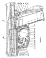
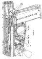
- Figure 1 shows a semi-automatic firearm with the trigger system of the current invention in its armed position.
- a pivot pin (24) is used to pivot the lower end of trigger (18) to the housing (1) and the trigger (18) is forwardly biased.
- a torsion spring (21) with a bend at its both ends is used to bias the trigger forwards.
- the torsion spring (21) is attached to the housing by coiling over the trigger pivot (24) and each of its bent ends placed against a pin (20) that is provided on the housing (1) and a pin (23) that is provided on the trigger (18) such that when the trigger (18) is pulled, the pin (23) on the trigger (18) extends the torsion spring (21) and once the trigger is released, the extended torsion spring (21) will urge the trigger (18) back to its original firing position.
- An adjustable screw as a trigger stop (22) is screwed through the trigger (18) and projects rearwardly out from the trigger (18).
- the rear portion of trigger stop (22) will touch the wall of the housing (1) to stop the rearward movement of the trigger (18).
- This adjustable screw (22) allows the clearance between the trigger wall and the trigger stop (22) to be reversibly adjusted to either increase or decrease backward movement of trigger (18), hence, regulating the amount of fulcrum effect.
- a trigger link (9) has its first end pivoted with upper end of said trigger (18) and its second end placed in front of and lower than said first end of trigger link (9).
- the second end of the trigger link (9) has a cross-bar (11) attached via a pivot pin (10) and also has a means of guiding the cross-bar (11) attached.
- a preferred guiding means is a lever (3) that is pivoted to the housing (1) at its upper end via a pivot pin (4) and the lower end of the lever (3) is free to rotate about the pivot pin (4) and is attached to pivot pin (10).
- Another guiding means comprises of a guide pin which extends from the pivotal point of the trigger link (9) with lever (3) and cross-bar (11), and an oblong opening on the housing (1) through which said guide pin can extend through and guided to move rearwards and forwards therewithin.
- the upper rear end of the cross-bar (11) is provided with a stepped cut out to provide a corner and the rear end of the cross-bar (11) is upwardly biased.
- a sear-link (15) that is rotatably pivoted to the housing (1) at its upper end with a pivot pin (13).
- the lower end of the sear-link (15) is free to rotate around the pivot pin (13) and is forwardly biased.
- the lower front end (41) of sear-link (15) can come into contact with the rear-end of the cross-bar (11) to mutually form a first engagement means.
- the lower front end (41) of the sear-link (15) is in contact with the corner formed on the rear-end of the cross-bar (11) as shown in Figures 1 to 3.
- the lower front end of the sear-link (15) is provided with a stepped cut-out to form a corner
- the upper rear end of the cross-bar (11) is In contact with the corner to form the first engagement means.
- the cross-bar (11) does not need to be provided with a corner formed by the stepped cut-out.
- FIG. 1 Another biasing means is illustrated in Figure 1 and the same means is used to describe the first embodiment of the improved firearm.
- the cross-bar (11) is integrally provided with an extension extending downwardly from the pivotal connection with the trigger link (9) and lever (3).
- the lower end of the sear-link (15) is also provided with an extension extending from the lower front end (41).
- a stretched elastic link (12) like a spring as shown in Figure (1), is used to connect both the extensions.
- both the rear end of the cross-bar (11) and the sear-link (15) are simultaneously biased in their intended direction.
- the extension the sear-link (15) is provided with a means of accommodating the rear end of said cross-bar (11).
- the accommodating means can be a perforation that extends from the front of the extension through which the rear end of the cross-bar (11) can be accommodated or preferably, the accommodating means is a groove provided on the side of the sear-link (14) such that the rear-end of the cross-bar (11) can be accommodated in the groove as illustrated in Figures 1 and 4.
- a stopping pin (14) is provided in front of the extension on the sear-link (15) and is attached to the firearm's housing (1) to prevent the forwardly biased sear-link (15) from rotating further.
- an adjustable screw (16) is provided through the back of the extension on the sear-link (15) such that the tip of the adjustable screw (16) abuts this stopping pin (14). Referring to Figure 1, when the lever (3) rotates counter-clockwise, the cutout corner of lever (11) will push against the lower front end (41) of sear-link (15), causing the sear-link (15) to rotate counter-clockwise about the pivot (13) thus moving the adjustable screw (16) away from the stopping pin (14).
- the adjustable screw (16) will be discussed in more detail later.
- a torsion spring is attached around each pivot pins (10) and (13) in a similar manner as that of the torsion spring (21) to bias the rear end of the cross-bar (11) and the lower end of the sear-link (15) in their intended direction.
- a stopping pin is provided in front of the sear-link (15).
- the sear-link (15) is provided with an extension extending downwardly from the lower front end (41), and a stopping pin (14) is placed in front of said extension.
- the extension is also provided with a means of accommodating the rear-end of the cross-bar (11).
- An adjustable screw (36) can also be provided on the extension to provide a means of adjusting the trigger sensitivity which will be discussed later.
- a sear-cam block (6) is placed in front of the sear-link (15) and above the cross-bar (11), and is essentially triangular in shape whereby the first triangular side is pivoted to the housing (1) via a pivot pin (8).
- the second side of the triangular sear-cam block (6) is provided with a protrusion (45) that is engageable with the forwardly biased sear-link (15) to form a second notch means.
- a notch (43) is provided on the forwardly biased sear-link (15), above the first engagement means, and is engageable with the protrusion (45) of the sear-cam block (6) such that when the second engagement means is engaged, the upper surface of the protrusion (45) is in contact with the lower surface of the notch (43).
- the third side is pivoted to the front end of a hammer link (48) with a pivot pin (5).
- the rear end of the hammer link (48) is connected to the hammer (38) with a pivot pin (37).
- the hammer (38) is attached to the housing (1) via pivot pin (36) and is free to rotate about this pivot pin (36).
- the hammer (38) in Figure 1 is shown in its cocked position.
- the hammer (38) is rotated clock-wise which simultaneously causes the hammer link (48) to be pulled rearwards and causes the hammer drive spring (34) on hammer drive (33) to be compressed.
- the hammer link (48) rotates the sear-cam block (6) clock-wise to engage the second engagement means which maintains the compression of the hammer drive spring (34) and the compressed drive spring (34) thereby biases the hammer link (48) towards the third side of the sear-cam block (6) which is locked from rotating around the pivot pin (8) due to the engagement of the second engagement means.
- Hammer drive (33) serves to push the hammer (38) out of its cocked position when the second engagement means is disengaged.
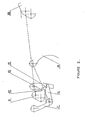
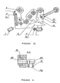
- FIG. 2 A simplified diagram of the first embodiment is shown in Figure 2 whereby the firearm is in the armed position.
- the hammer is shown in the cocked position, the first engagement means shown as engaged, and the second engagement means shown as engaged to prevent the sear-cam block (6) from rotating.
- trigger (18) when actuated, it rotates clockwise around the pivot pin (24) and drags the trigger link (9) rearwards.
- the rearward movement of the trigger link (9) causes the lever (3) to rotate counter-clockwise around the pivot pin (4), which also causes the cross-bar (11) to move rearwards.
- the corner formed by step cutout of said cross-bar (11) pushes the lower front end (41) of sear-link (15) backwards.
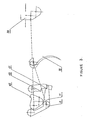
- the reactive force forces the breechblock (52) rearwards which pushes the hammer (38) to rotate clockwise beyond its initial cocked position as shown in Figures 1 and 2 until the hammer (38) reaches its rearmost position as illustrated in Figure 4 and compressing the hammer drive spring (34).
- the hammer (38) rotation pulls the hammer link (48) rearwards, thereby causing the sear-cam block (6) to rotate clockwise beyond its initial starting position shown in Figures 1 and 2 and causing the lower surface of the protrusion (45) of sear-cam block (6) to push against the upper surface of the cross-bar (11) until the corner formed by the stepped cutout of the cross-bar (11) becomes disengaged with the lower front end (41) of sear-link (15) as shown in Figure 4.
- the stretched elastic link (12) pulls the extensions of sear-link (15) and cross-bar (11) closer, thereby rotating sear-link (15) clockwise.
- the recoil of the spring (51) on the breechblock (52) forces the breechblock forwards and releases the hammer drive spring (34) from its compressed state.
- the hammer drive spring (34) extends from its compressed state, causing the hammer drive (33) to push hammer (38) counter-clockwise, thereby reengaging the second engagement means; i.e. reengaging the protrusion (45) of sear-cam block (6) with notch (43) of sear-link (15).
- the sensitivity of the firearm is defined by the amount of engagement between the protrusion (45) of sear-cam block (6) and the notch (43) and the sensitivity, and specifically the sensitivity is defined by the amount of contact area between the upper surface of the protrusion (45) and the lower surface of the notch (43).
- the distance travelled by the trigger to discharge the firearm is equal to the distance travelled by the sear-link (15) to release the sear-cam block (6), and such a 1:1 ratio is achieved with the trigger arrangement described above.
- This first embodiment is used to form the preferred embodiment of the firearm which is convertible from semi-automatic and fully automatic.
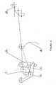
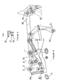
- the preferred embodiment of the firearm is shown in Figure 5 which also shows the firearm in its armed position.
- the firearm is convertible between a semi-automatic and a fully automatic firearm.
- trigger In addition to the trigger (18), trigger link (9), lever (3), cross-bar (11), sear-link (15), sear-cam block (6), hammer link (48), hammer (38) and hammer drive (33) that forms the basic structure of the first embodiment, an additional cross-bar (11a) and a switch (19) are added to form the preferred embodiment.
- the preferred means of biasing the cross-bars (11, 11a) upwardly and the sear-link (15) forwardly is also shown in Figure 5.
- the assembly and the operation of the preferred embodiment of this invention are herein described.
- the additional cross-bar (11a) is also pivoted to the lower end of lever (3) and the trigger link (9) at the pivot pin (10).
- the upper end of the lever (3) of the preferred embodiment is thicker on its upper end so that the trigger link (9) and two cross-bars (11) and (11a) can be accommodated and pivoted to the lower end of lever (3) by pivot pin (10).
- the upper end of the lever (3) is provided with a forward extending arm (3a) with two springs (2a, 2b) [only one shown in Figure 5] having their upper ends attached to the forward extending arm (3a).
- a forward extending arm (11b) is provided on the front end of each levers (11, 11a) [only one shown in Figure 5] for attaching with the lower end of springs (2a, 2b), each arm attaching with only one end of a spring.
- the springs (2a, 2b) act in compression against cross-bars (11, 11a), and the rear end of the cross-bars (11, 11a) is upwardly biased.
- the levers (11) and (11a) are each provided with an upward extending arm that extends upwardly from the pivot pin (10) and abuts the pin (3b) that is fixed on the lever (3) which stops the cross-bars (11, 11a) from rotating during assembly.
- the adjustable screw (7) abuts the front end of the arm (11b).
- a spring (27) has its upper end attached to the housing (1) between the sear (15) and the trigger (38).
- the lower end of the spring (27) is provided with a cup (26) with its convex surface cupping the pin (15a) provided on sear (15).
- This spring (27) constantly exerts a force on the pin (15a) to push the sear (15) forward.
- the fiream is provided with a means of selecting which of the cross-bars (11) and (11a) is to be engaged with the lower front end (41) of the sear-link (15) and selecting means can also can also be used disengage both the cross-bars (11) and (11a) from the lower front end (41) of sear-link (15) which provides for the safety of the firearm.
- the selecting means is provided by the switch (19) which consists of a shaft (60), a spindle (58), and switch cap (56).
- the switch shaft (60) is placed between the pendulum (3) and the sear (15) and directly above both the cross-bars (11) and (11a).
- a switch spindle (58) is provided at one end of the switch shaft (60) that extends into and out through the firearm's housing (1).
- a switch cap (56) is rotatably fixed onto the exterior of the firearm's housing (1) by having the switch spindle (58) extending into the switch cap (56).
- the lower side of the switch cap (56) is provided with dimples such that the cap (25a) comprising a head and a pin that is provided under the switch cap (56) with a spring (25) coiled around the pin can be received within any of the dimple when the switch cap (56) is rotated to provide different radial location of the switch shaft (60).
- the different location of the switch shaft (60) can be achieved by having serrations or teeths on the lower side of the switch cap (56) to engage with a pin.
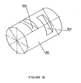
- the switch shaft (60) is provided with two parallel grooves (59a, 59b) that are both perpendicular to the axis with their ends not aligned to each other [ Figure 12].
- Each groove is wide enough to allow a cross-bar to be received therein such that when the shaft (60) is rotated by rotating switch cap (56), either one of the groove is positioned over a cross-bar and the cross-bar is pushed into the groove by the spring attached on the arm forward extending arm (11b) until the corner formed by the stepped cut-out portion of the cross-bar is engaged with the lower front end (41) of sear-link (15).
- the other cross-bar that does not have a groove positioned over its upper portion is forced to be disengaged with the lower front end (41) sear-link (15).
- the switch (19) can also be rotated to disengage both the cross-bars (11) and (11a) with the sear-link (15).
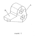
- the sear-cam block (6) of the preferred embodiment differs from the first embodiment by having different thickness at the lower surface of the protrusion (45). This difference in thickness is shown in Figure 7.
- the protrusion (45) can alternatively be either thinner at its lower left or lower right side. Due to the difference in the thickness, the distance from the lower surface of the protrusion (45) to the upper surface of the cross-bars (11) and (11a) when they are engaged with the lower front end (41) of sear-link (15) is different from one another, as illustrated in Figure 8.
- the rotation of the lever (3) causes the cross-bar (11) to push the sear-link (15) rearward, thereby releasing the sear-cam block (6) to allow the hammer drive spring (34) on hammer drive (33) to rotate the hammer (38) counter-clockwise to fire the bullet out.
- the reactive force from the explosion will force the breech block (52) rearwards which pushes the hammer (38) to rotate clockwise beyond its initial cocked position and pushing the hammer (38) to its rearmost position, dragging the hammer link (48) rearward and rotating the sear-cam block (6) beyond its initial engaged position with second engagement means as shown in figures 5 and 6 and pushing the cross-bar (11) to be disengaged with the first engagement means.
- the spring (27) will push the sear-link (15) forward as shown in Figure 10.
- the return of the sear-cam block (6) does not push the cross-bar (11a) out of engagement with the first engagement means as illustrated in Figure 10, thereby remaining the engagement between the cross-bar (11a) and lower front end (41) and remaining the sear-link (15) being pushed rearwards by the cross-bar (11a).
- the hammer drive spring (33) pushes the hammer (38) counter-clockwise which forces the hammer link (48) forwards, thereby rotating the sear-cam block (6) counter-clockwise.
- an additional safety switch (29) is provided on the preferred embodiment of the firearm that stops the hammer (38) from slamming the firing pin (47) [Figure 5].
- the safety switch (29) consist of a flange (31), spindle and switch cap, wherein the flange (31) is placed infront of the hammer.
- the safety switch (29) has a switch cap that is rotatably fixed to the housing by a spindle that extends from the switch cap into and through the firearm's housing (1) and into the housing's inner surface.
- switch cap is serrated or teethed to be engageable with the vertex of a cap (30a) covering a spring (30) that has its upper end connected to the housing (1).
- the other end of the shaft is provided with a flange (31).
- the hammer (38) is provided with a groove (39) on the side of the hammer such that the groove (39) starts from the front and extends rearwards for receiving the flange (31).
- a notch (40) is provided on the mouth of the groove (39).
- the flange (31) can be rotated into two position whereby one position will engage the flange (31) with the notch (40), thereby blocking the hammer (38) from slamming the firing pin (47).
- the flange (31) When the flange (31) is rotated into the other position, the flange (31) is positioned over the mouth of the groove (39) such that when the hammer (38) is not blocked and flange (31) is slidably received within the groove (39) when the hammer (38) rotates to discharge the firearm.
- Such trigger arrangement for the preferred embodiment also provides a 1:1 ratio between the distance travelled by trigger (18) to discharge the firearm and the distance travelled by sear (15) to release latch (6) as illustrated in Figures 9 and 6, where the distance travelled by the trigger (18) to discharge the firearm, labelled as 'B' [ Figure 9] is the same as the distance travelled by the sear (15) to release the latch (6), labelled as 'A', such ratio of which is not achieved in many conventional firearms.
- the reactive force is dampened by 2 springs (50a, 50b) that are placed beside each other [one shown in Figure 5].
- the spring guide (51) of each spring has their front end fixed onto the housing (1) and extends into and through the breech block (52) with its rear end fixed onto the rear end of the breech block cover (1a).
- Each spring (50a, 50b) is coiled around a spring guide (51) and has its front end fixed onto the breech block (52) and its rear end fixed onto the breech block cover (1a) on the rear end of the firearm, such that when the reactive force of the explosion is transferred onto the breech block (52), the breech block moves rearwards, thereby squeezing the springs (50a, 50b).
- An additional spring (53) is provided above the springs and is embedded on the breech block (52).
- the rear end of the spring (53) is provided with a cap (54) that protrudes out of the breech block slightly. This further dampens the clashing of the breech block with the housing (1).
- An additional handle (28) is provided in front of the whole trigger system to provide additional stability for the user during shooting.
- the handle (28) is preferably foldable to allow to the user to store the handle when the user does not wish to use the handle.
Landscapes
- Engineering & Computer Science (AREA)
- General Engineering & Computer Science (AREA)
- Toys (AREA)
- Electrophonic Musical Instruments (AREA)
- Curing Cements, Concrete, And Artificial Stone (AREA)
- Polymers With Sulfur, Phosphorus Or Metals In The Main Chain (AREA)
- Organic Low-Molecular-Weight Compounds And Preparation Thereof (AREA)
Claims (21)
- Abzugseinheit für das Lösen eines Mechanismus, der für das Abfeuern einer Schusswaffe vorgespannt ist, wobei die Einheit aufweist:- einen Abzug (18), der in operativen Kontakt ist mit einer- Abzugseinheit, welche gegen das Abfeuern des vorgespannten Mechanismus gesperrt ist; wobeider Abzug (18) betriebsfähig ist, die Sperrung der Abzugseinheit zu lösen, um das Auslösen des vorgespannten Mechanismus zu ermöglichen,
wobei die Abzugseinheit vor dem Abzug (18) vorgesehen ist; dadurch gekennzeichnet, dass
die Abzugseinheit in einem erweiterten Abzugs-Schutzgehäuse untergebracht ist. - Abzugseinheit nach Anspruch 1, welche aufweist:- ein Hammermittel (38), welches vorgespannt ist, um die Schusswaffe abzufeuern und welches vom Abfeuern durch eine Auslösehebeleinheit gesperrt ist;- eine Auslösehebeleinheit mit drei Komponenten, die hintereinander an zwei Einrastmitteln ineinander eingreifen, welche die Auslösehebeleinheit von einem Betätigen der Hammermittel (38) gegenseitig sperren;- ein Abzugsmittel (18), welches mit der Auslösehebeleinheit in operativen Kontakt ist, um das Hammermittel (38) zu betätigen.
- Abzugseinheit nach Anspruch 2, wobei die Auslösehebeleinheit aufweist:- einen Auslösehebel-Nockenblock (6);- ein Auslösehebel-Verbindungsstück (15); und- eine Querstange (11);wobei der Auslösehebel-Nockenblock (6) gegen besagtes Hammermittel (38) vorgespannt ist, und drehbar gelagert ist, um nach oben zu schwenken,
wobei die Querstange (11) mit den Auslösehebel-Verbindungsstück (15) an einem ersten Einrastmittel im Eingriff ist, und die Querstange (11) gegen ein Lösen des ersten Einrastmittels mit den Auslösehebel-Verbindungsstück (15) vorgespannt ist; und
wobei das Auslösehebel-Verbindungsstück (15) mit dem Auslösehebel-Nockenblock (6) an einem zweiten Einrastmittel in Eingriff ist, welches an sich ergänzenden berührenden Flächen zwischen den Auslösehebel-Nockenblock (6) und den Auslösehebel-Verbindungsstück (15) vorgesehen ist, wobei das Auslösehebel-Verbindungsstück gegenüber dem Aufwärtsschwenken des Auslösehebel-Nockenblocks (6) vorgespannt ist, um gegenseitig an den zweiten Einrastmittel einzurasten. - Abzugseinheit nach Anspruch 3, wobei das Abzugsmittel (18) die Querstange (11) im Einklang mit der Bewegung des Abzuges bewegt, so dass das Auslösehebel-Verbindungsstück (15) bewegt wird, um das zweite Einrastmittel zu entsperren.
- Abzugseinheit nach Anspruch 3, wobei das Abzugsmittel (18) aufweist:- ein Abzugs-Schutzgehäuse, um darin die folgenden Komponenten unterzubringen;- einen Abzug (18), dessen erstes Ende im Bezug auf das Gehäuse drehbar gelagert ist;- ein Abzugs-Verbindungsstück (9), dessen erstes Ende im Bezug auf das zweite Ende des Abzuges (18) drehbar gelagert ist;- eine Querstange (11), deren erstes Ende in Bezug auf das Abzugs-Verbindungsstück (19) drehbar gelagert ist, und dessen zweites Ende nach oben vorgespannt ist;- ein Auslösehebel-Verbindungsstück (15) dessen erstes Ende im Bezug auf das Gehäuse (1) drehbar gelagert ist, dessen zweites Ende mit den zweiten Ende der Querstange (11) in Kontakt ist, um gegenseitig ein erstes Einrastmittel zu bilden, und welches nach vorne vorgespannt ist;- einen Auslösehebel-Nockenblock (6) von im wesentlichen dreieckiger Form, dessen erster Winkelbereich in Bezug auf das Gehäuse (1) drehbar gelagert ist, und dessen zweiter Winkelbereich in Kontakt mit dem Auslösehebel-Verbindungsstück (15) ist, um gegenseitig ein zweites Einrastmittel zu bilden;- ein Hammer-Verbindungsstück (48), dessen erstes Ende in Bezug auf den dritten Winkelbereich des Auslösehebel-Nockenblocks (6) drehbar gelagert ist, und dessen zweites Ende in Bezug auf einen Hammer (38) drehbar gelagert ist;wobei das Hammer-Verbindungsstück (48) in Folge des Spannens des Hammers (38) in Richtung des dritten Winkelbereichs des Auslösehebel-Nockenblocks (6) vorgespannt wird, um den zweiten Winkelbereich des Auslösehebel-Nockenblocks (6) zu drängen, so dass dieser nach oben schwenkt, und nur von dem zweiten Einrastmittel zurückgehalten wird;
wobei das Zeihen des Abzuges eine Bewegung überträgt, um die Querstange in Richtung des Auslösehebel-Verbindungsstücks (15) zu drücken, um das Auslösehebel-Verbindungsstück (15) zu schwenken, um das zweite Einrastmittel zwischen den Auslösehebel-Verbindungsstück (15) und dem Auslösehebel-Nockenblock (6) zu entsperren, wodurch das vorgespannte Hammer-Verbindungsstück (48) gelöst wird, um den Hammer (38) umzulegen und die Schusswaffe abzufeuern. - Abzugseinheit nach Anspruch 5, wobei das erste Ende des Abzuges (18), welches in Bezug auf das Gehäuse (1) drehbar gelagert ist, das untere Ende aufweist, und wobei das zweite Ende mit dem Abzugs-Verbindungsstück (9) drehbar verbunden ist, und wobei das Drücken des Abzuges (18) die Abzugsbewegung über das Abzugs-Verbindungsstück (9) übermittelt, um die Querstange zu bewegen, um das zweite Einrastmittel zu entsperren.
- Abzugseinheit nach Anspruch 5, welche weiters einen Hebel (3) aufweist, dessen erstes Ende in Bezug auf das Gehäuse drehbar gelagert ist und dessen zweites Ende in Bezug auf das zweite Ende des Abzugs-Verbindungsstücks (9) drehbar gelagert ist.
- Abzugseinheit nach Anspruch 7, wobei das Auslösehebel-Verbindungsstück (15) mit einer Erweiterung einteilig ausgebildet ist, welche sich über das erste Einrastmittel hinweg nach unten hin erstreckt, wobei die Erweiterung mit einem Mittel ausgestattet ist, um die Querstange (11) unterzubringen, und die Erweiterung mit einer justierbaren Schraube (16) und einem Anschlagstift (14) versehen ist, wobei die justierbare Schraube durch die Erweiterung hindurch vorgesehen ist, wobei der Anschlagstift (14) an dem Gehäuse (1) angebracht ist, wobei die Spitze der justierbaren Schraube (16) so an dem Anschlagstift (14) anliegt, dass der Anteil des Eingriffes des zweiten Einrastmittels über die justierbare Schraube (16) justiert werden kann.
- Abzugseinheit nach Anspruch 8, wobei die Querstange (11) mit einer Erweiterung einteilig ausgebildet ist, welche sich von ihrer drehbar gelagerten Verbindung mit dem Hebel (3) nach unten erstreckt, und in Richtung des Auslösehebel-Verbindungsstücks (15) vorgespannt ist.
- Abzugseinheit nach Anspruch 9, wobei die Erweiterung der Querstange (11), sowie die Erweiterung des Auslösehebel-Verbindungsstück (15) durch Federmittel gehalten sind, welche die Erweiterungen in Richtung zueinander drängen.
- Abzugseinheit nach Anspruch 8, welche weiters eine Feder aufweist, deren ein Ende an dem Gehäuse (1) angebracht ist, und dessen anderes Ende in operativem Kontakt mit dem Auslösehebel-Verbindungsstück (15) ist, um das Auslösehebel-Verbindungsstück (15) nach vorne zu drängen.
- Abzugseinheit nach Anspruch 11, welche weiters eine Feder aufweist, deren ein Ende in operativem Kontakt mit dem Hebel (3) ist, und deren anderes Ende in operativem Kontakt mit der Querstange (11) ist, um das zweite Ende der Querstange nach oben zu drängen.
- Abzugseinheit nach Anspruch 5, wobei der Hammer (38) durch die Explosion des Projektils automatisch wiedergespannt wird, wobei das automatische Wiederspannen des Hammers (38) erzwingt, dass der zweite Winkelbereich des Auslösehebel-Nockenblocks (16) nach unten schwenkt, und in Eingriff mit der Querstange (11) gelangt, um das erste Einrastmittel zu lösen, und das zweite Einrastmittel wieder einzurasten, wobei der Abzug (18) gelöst werden muss, um das erste Einrastmittel wieder einzurasten.
- Abzugseinheit nach Anspruch 5, welche weiters aufweist:- eine zweite Querstange, wobei das erste Ende der zweiten Querstange im Bezug auf das zweite Ende des Abzuges-Verbindungsstücks drehbar gelagert ist, und das zweite Ende nach oben vorgespannt ist, und in Kontakt mit dem zweiten Ende des Auslösehebel-Verbindungsstücks (15) ist, um gemeinsam ein erstes Einrastmittel zu bilden; und- ein Mittel, um eine der Querstangen auszuwählen, um in Kontakt mit dem zweiten Ende des Auslösehebel-Verbindungsstücks (15) zu sein, um ein erstes Einrastmittel zu bilden;- wobei die untere Oberfläche des zweiten Winkelbereichs des Auslösehebel-Nockenblocks (16) mit unterschiedlicher Dicke versehen ist;wobei die Querstange (11) die dem zweiten Winkelbereich des Auslösehebel-Nockenblocks (6) am nächsten ist, ausgewählt ist, um mit dem zweiten Ende des Auslösehebel-Verbindungsstücks (15) einrastbar zu sein, um das erste Einrastmittel zu bilden, wobei der zweite Winkelbereich des Auslösehebel-Nockenblocks (6) mit der ausgewählten Querstange (11) in Eingriff ist, um das erste Einrastmittel zu lösen, und um das zweite Einrastmittel wiedereinzurasten während der Hammer (38) automatisch wiedergespannt wird, und wobei der Abzug (18) gelöste werden muss, um das erste Einrastmittel wieder einzurasten; und
wenn die Querstange (11), welche am weitesten von dem zweiten Winkelbereich des Auslösehebel-Nockenblocks (6) entfernt ist, ausgewählt ist, um mit dem zweiten Ende des Auslösehebel-Verbindungsstücks (15) einrastbar zu sein, um das erste Einrastmittel zu bilden, dann gelangt der zweite Winkelbereich des Auslösehebel-Nockenblocks (6) nicht mit der ausgewählten Querstange (11) in Eingriff, um das erste Einrastmittel zu lösen, und das zweite Einrastmittel wird während des automatischen Wiederspannens des Hammers (38) nicht wieder eingerastet, und der Abzug (18) muss nicht gelöst werden, um eine weitere Patrone der Schusswaffe abzufeuern. - Abzugseinheit nach einem der Ansprüche 3 bis 14, wobei das zweite Ende der Querstange (11) eine abgestufte Aussparung für den Kontakt mit dem zweiten Ende des Auslösehebel-Verbindungsstücks (15) aufweist, um gemeinsam ein erstes Einrastmittel zu bilden, und um ein überstreifendes Entriegeln des ersten Einrastmittels zu ermöglichen.
- Abzugseinheit nach Anspruch 12 und 15, wobei das Auswählmittel eine Welle (60) aufweist, die sich über beide Hebel (3) erstreckt, wobei die Welle (60) zwei parallele Nuten (59a, 59b) aufweist, welche im rechten Winkel auf die Achse der Welle (60) ausgerichtet sind, mit nicht aufeinander ausgerichteten Enden; eine Spindel (58), welche an einem Ende der Welle (60) anschließt und sich in das Gehäuse (1) erstreckt und eine Verbindung mit einem Schaltaufsatz (56) an der Außenseite des Gehäuses herstellt, wobei der Schaltaufsatz mit Vertiefungen versehen ist; und einen Zapfen in nächster Nähe zu dem Schaltaufsatz (56), wobei der Zapfen mit einem Aufsatz mit einer Erhebung versehen ist, die mit den Vertiefungen auf dem Schaltaufsatz (56) in Eingriff bringbar ist, so dass verschiedene radiale Anordnungen der Welle vorgesehen sind, wenn der Schaltaufsatz gedreht wird, so dass entweder eine oder keine der Nuten oberhalb eines Hebels (3) angeordnet werden können, um diesen aufzunehmen.
- Abzugseinheit nach einem der Ansprüche 5 bis 14, welche weiters einen Sicherheitsschalter (29) aufweist, wobei der Sicherheitsschalter einen Flansch (31) aufweist, wobei der Flansch vor dem Hammer (18) angeordnet ist; eine Spindel, welche an einem Ende der Welle anschließt, und sich in das Gehäuse erstreckt, und die Verbindung zu einem Schaltaufsatz (56) an der Außenseite des Gehäuses (1) herstellt, wobei der Schaltaufsatz (56) gezackt ist; eine Feder in nächster Nähe zu dem Schaltaufsatz, wobei die Feder mit einem Aufsatz versehen ist, der eine Erhebung aufweist, die mit den Zacken auf den Schaltaufsatz (56) in Eingriff bringbar ist, um verschiedene radiale Positionen auf dem Flansch vorzusehen, indem der Schaltaufsatz (56) gedreht wird; eine Nut, die auf dem Hammer (38) vorgesehen ist, so dass sich die Nut von der Vorderseite des Hammers erstreckt; und eine Aussparung, die an der Öffnung der Nut vorgesehen ist, so dass der Flansch gedreht werden kann, um innerhalb der Nut aufgenommen zu werden oder in der Aussparung aufgenommen zu werden, indem der Schaltaufsatz (56) gedreht wird.
- Abzugseinheit nach einem der vorhergehenden Ansprüche, wobei der Hammer hinter dem Abzug angeordnet ist.
- Schusswaffe, welche eine Abzugseinheit nach einem der vorhergehenden Ansprüche enthält.
- Schusswaffe nach Anspruch 19, welche ein hinter dem Abzug angeordnetes Magazingehäuse enthält.
- Schusswaffe nach Anspruch 19, welche ein Magazingehäuse aufweist, welches Teil eines Pistolengriffes für die Abzugshand des Benutzers ist.
Applications Claiming Priority (3)
| Application Number | Priority Date | Filing Date | Title |
|---|---|---|---|
| MYPI20031903 | 2003-05-22 | ||
| MYPI20033645 | 2003-09-24 | ||
| PCT/IB2004/001838 WO2004104507A1 (en) | 2003-05-22 | 2004-05-21 | Improved firearm |
Publications (2)
| Publication Number | Publication Date |
|---|---|
| EP1634032A1 EP1634032A1 (de) | 2006-03-15 |
| EP1634032B1 true EP1634032B1 (de) | 2007-01-17 |
Family
ID=33479066
Family Applications (1)
| Application Number | Title | Priority Date | Filing Date |
|---|---|---|---|
| EP04734328A Expired - Lifetime EP1634032B1 (de) | 2003-05-22 | 2004-05-21 | Verbesserte feuerwaffe |
Country Status (5)
| Country | Link |
|---|---|
| EP (1) | EP1634032B1 (de) |
| AT (1) | ATE352019T1 (de) |
| AU (1) | AU2004241370A1 (de) |
| DE (1) | DE602004004395T2 (de) |
| WO (1) | WO2004104507A1 (de) |
Cited By (1)
| Publication number | Priority date | Publication date | Assignee | Title |
|---|---|---|---|---|
| US11199373B1 (en) | 2020-03-30 | 2021-12-14 | Next Level Designs, Llc | Fire control / trigger mechanism |
Families Citing this family (1)
| Publication number | Priority date | Publication date | Assignee | Title |
|---|---|---|---|---|
| RU2007129577A (ru) * | 2005-03-02 | 2009-04-10 | Индустриас Эл Гамо, Са (Es) | Пистолет с газовым исполнительным механизмом |
Family Cites Families (4)
| Publication number | Priority date | Publication date | Assignee | Title |
|---|---|---|---|---|
| FR500989A (fr) * | 1918-07-16 | 1920-03-30 | Vincenzo Cassetta | Perfectionnements apportés aux mitrailleuses |
| US1436536A (en) * | 1922-06-09 | 1922-11-21 | Herbert O Russell | Spade grip for machine guns |
| FR683322A (fr) * | 1928-10-31 | 1930-06-11 | Fusil automatique | |
| US4664015A (en) * | 1985-07-24 | 1987-05-12 | Kennedy Joseph E | Automatic gun with improved firing mechanism |
-
2004
- 2004-05-21 AT AT04734328T patent/ATE352019T1/de not_active IP Right Cessation
- 2004-05-21 DE DE602004004395T patent/DE602004004395T2/de not_active Expired - Fee Related
- 2004-05-21 WO PCT/IB2004/001838 patent/WO2004104507A1/en not_active Ceased
- 2004-05-21 AU AU2004241370A patent/AU2004241370A1/en not_active Abandoned
- 2004-05-21 EP EP04734328A patent/EP1634032B1/de not_active Expired - Lifetime
Cited By (3)
| Publication number | Priority date | Publication date | Assignee | Title |
|---|---|---|---|---|
| US11199373B1 (en) | 2020-03-30 | 2021-12-14 | Next Level Designs, Llc | Fire control / trigger mechanism |
| US11326848B2 (en) | 2020-03-30 | 2022-05-10 | Next Level Designs, Llc | Fire control/trigger mechanism |
| US12163747B2 (en) | 2020-03-30 | 2024-12-10 | Next Level Designs, Llc | Fire control / trigger mechanism |
Also Published As
| Publication number | Publication date |
|---|---|
| WO2004104507A1 (en) | 2004-12-02 |
| DE602004004395D1 (de) | 2007-03-08 |
| AU2004241370A1 (en) | 2004-12-02 |
| EP1634032A1 (de) | 2006-03-15 |
| DE602004004395T2 (de) | 2007-11-08 |
| ATE352019T1 (de) | 2007-02-15 |
Similar Documents
| Publication | Publication Date | Title |
|---|---|---|
| US9518793B1 (en) | Trigger mechanism | |
| US6341442B1 (en) | Double action pistol | |
| US7617628B2 (en) | Fire control mechanism for a firearm | |
| US6415702B1 (en) | Double action semi-automatic handgun | |
| US5680722A (en) | Fire control system for firearms | |
| EP3129739B1 (de) | Abzugssystem für feuerwaffen | |
| US5623114A (en) | Selectable fire trigger mechanism | |
| US5913261A (en) | Trigger arrangement | |
| US4023465A (en) | Firearm | |
| US9267751B2 (en) | Trigger mechanisms | |
| US9500421B1 (en) | Firearm charging handle | |
| EP2185886B1 (de) | Revolverabzugmechanismus | |
| US20040103575A1 (en) | Over-and-under shotgun apparatus and method | |
| US20060162220A1 (en) | Positive striker lock safety for use with a firearm | |
| US4545143A (en) | Trigger mechanism for double barrel shotgun | |
| US12209827B2 (en) | Trigger group for striker-fired firearms | |
| US2464427A (en) | Double-action mechanism for pistols | |
| EP2212641A1 (de) | Doppelt wirkendes auslösersystem mit kurzer rücksetzung | |
| US4448109A (en) | Automatic or semi-automatic firearm | |
| US5915935A (en) | Cocking trigger device | |
| US4403436A (en) | Trigger mechanism for multiple barrel firearm providing barrel selection | |
| EP1634032B1 (de) | Verbesserte feuerwaffe | |
| US4910903A (en) | Trigger mechanism, particularly for sports pistols | |
| ZA200508556B (en) | Improved firearm | |
| KR100389182B1 (ko) | 완전자동식 자동 장전 무기 |
Legal Events
| Date | Code | Title | Description |
|---|---|---|---|
| PUAI | Public reference made under article 153(3) epc to a published international application that has entered the european phase |
Free format text: ORIGINAL CODE: 0009012 |
|
| 17P | Request for examination filed |
Effective date: 20051221 |
|
| AK | Designated contracting states |
Kind code of ref document: A1 Designated state(s): AT BE BG CH CY CZ DE DK EE ES FI FR GB GR HU IE IT LI LU MC NL PL PT RO SE SI SK TR |
|
| GRAP | Despatch of communication of intention to grant a patent |
Free format text: ORIGINAL CODE: EPIDOSNIGR1 |
|
| DAX | Request for extension of the european patent (deleted) | ||
| GRAS | Grant fee paid |
Free format text: ORIGINAL CODE: EPIDOSNIGR3 |
|
| GRAA | (expected) grant |
Free format text: ORIGINAL CODE: 0009210 |
|
| AK | Designated contracting states |
Kind code of ref document: B1 Designated state(s): AT BE BG CH CY CZ DE DK EE ES FI FR GB GR HU IE IT LI LU MC NL PL PT RO SE SI SK TR |
|
| PG25 | Lapsed in a contracting state [announced via postgrant information from national office to epo] |
Ref country code: FI Free format text: LAPSE BECAUSE OF FAILURE TO SUBMIT A TRANSLATION OF THE DESCRIPTION OR TO PAY THE FEE WITHIN THE PRESCRIBED TIME-LIMIT Effective date: 20070117 Ref country code: PL Free format text: LAPSE BECAUSE OF FAILURE TO SUBMIT A TRANSLATION OF THE DESCRIPTION OR TO PAY THE FEE WITHIN THE PRESCRIBED TIME-LIMIT Effective date: 20070117 Ref country code: DK Free format text: LAPSE BECAUSE OF FAILURE TO SUBMIT A TRANSLATION OF THE DESCRIPTION OR TO PAY THE FEE WITHIN THE PRESCRIBED TIME-LIMIT Effective date: 20070117 Ref country code: CH Free format text: LAPSE BECAUSE OF FAILURE TO SUBMIT A TRANSLATION OF THE DESCRIPTION OR TO PAY THE FEE WITHIN THE PRESCRIBED TIME-LIMIT Effective date: 20070117 Ref country code: LI Free format text: LAPSE BECAUSE OF FAILURE TO SUBMIT A TRANSLATION OF THE DESCRIPTION OR TO PAY THE FEE WITHIN THE PRESCRIBED TIME-LIMIT Effective date: 20070117 Ref country code: AT Free format text: LAPSE BECAUSE OF FAILURE TO SUBMIT A TRANSLATION OF THE DESCRIPTION OR TO PAY THE FEE WITHIN THE PRESCRIBED TIME-LIMIT Effective date: 20070117 Ref country code: SI Free format text: LAPSE BECAUSE OF FAILURE TO SUBMIT A TRANSLATION OF THE DESCRIPTION OR TO PAY THE FEE WITHIN THE PRESCRIBED TIME-LIMIT Effective date: 20070117 Ref country code: NL Free format text: LAPSE BECAUSE OF FAILURE TO SUBMIT A TRANSLATION OF THE DESCRIPTION OR TO PAY THE FEE WITHIN THE PRESCRIBED TIME-LIMIT Effective date: 20070117 |
|
| REG | Reference to a national code |
Ref country code: GB Ref legal event code: FG4D |
|
| REG | Reference to a national code |
Ref country code: CH Ref legal event code: EP |
|
| REG | Reference to a national code |
Ref country code: IE Ref legal event code: FG4D |
|
| REF | Corresponds to: |
Ref document number: 602004004395 Country of ref document: DE Date of ref document: 20070308 Kind code of ref document: P |
|
| PG25 | Lapsed in a contracting state [announced via postgrant information from national office to epo] |
Ref country code: SE Free format text: LAPSE BECAUSE OF FAILURE TO SUBMIT A TRANSLATION OF THE DESCRIPTION OR TO PAY THE FEE WITHIN THE PRESCRIBED TIME-LIMIT Effective date: 20070417 Ref country code: BG Free format text: LAPSE BECAUSE OF FAILURE TO SUBMIT A TRANSLATION OF THE DESCRIPTION OR TO PAY THE FEE WITHIN THE PRESCRIBED TIME-LIMIT Effective date: 20070417 |
|
| PG25 | Lapsed in a contracting state [announced via postgrant information from national office to epo] |
Ref country code: ES Free format text: LAPSE BECAUSE OF FAILURE TO SUBMIT A TRANSLATION OF THE DESCRIPTION OR TO PAY THE FEE WITHIN THE PRESCRIBED TIME-LIMIT Effective date: 20070428 |
|
| PG25 | Lapsed in a contracting state [announced via postgrant information from national office to epo] |
Ref country code: PT Free format text: LAPSE BECAUSE OF FAILURE TO SUBMIT A TRANSLATION OF THE DESCRIPTION OR TO PAY THE FEE WITHIN THE PRESCRIBED TIME-LIMIT Effective date: 20070618 |
|
| NLV1 | Nl: lapsed or annulled due to failure to fulfill the requirements of art. 29p and 29m of the patents act | ||
| REG | Reference to a national code |
Ref country code: CH Ref legal event code: PL |
|
| PLBE | No opposition filed within time limit |
Free format text: ORIGINAL CODE: 0009261 |
|
| STAA | Information on the status of an ep patent application or granted ep patent |
Free format text: STATUS: NO OPPOSITION FILED WITHIN TIME LIMIT |
|
| 26N | No opposition filed |
Effective date: 20071018 |
|
| PG25 | Lapsed in a contracting state [announced via postgrant information from national office to epo] |
Ref country code: CZ Free format text: LAPSE BECAUSE OF FAILURE TO SUBMIT A TRANSLATION OF THE DESCRIPTION OR TO PAY THE FEE WITHIN THE PRESCRIBED TIME-LIMIT Effective date: 20070117 Ref country code: RO Free format text: LAPSE BECAUSE OF FAILURE TO SUBMIT A TRANSLATION OF THE DESCRIPTION OR TO PAY THE FEE WITHIN THE PRESCRIBED TIME-LIMIT Effective date: 20070117 |
|
| PG25 | Lapsed in a contracting state [announced via postgrant information from national office to epo] |
Ref country code: MC Free format text: LAPSE BECAUSE OF NON-PAYMENT OF DUE FEES Effective date: 20070531 |
|
| PG25 | Lapsed in a contracting state [announced via postgrant information from national office to epo] |
Ref country code: FR Free format text: LAPSE BECAUSE OF FAILURE TO SUBMIT A TRANSLATION OF THE DESCRIPTION OR TO PAY THE FEE WITHIN THE PRESCRIBED TIME-LIMIT Effective date: 20070907 Ref country code: IT Free format text: LAPSE BECAUSE OF FAILURE TO SUBMIT A TRANSLATION OF THE DESCRIPTION OR TO PAY THE FEE WITHIN THE PRESCRIBED TIME-LIMIT Effective date: 20070117 Ref country code: GR Free format text: LAPSE BECAUSE OF FAILURE TO SUBMIT A TRANSLATION OF THE DESCRIPTION OR TO PAY THE FEE WITHIN THE PRESCRIBED TIME-LIMIT Effective date: 20070418 |
|
| PG25 | Lapsed in a contracting state [announced via postgrant information from national office to epo] |
Ref country code: IE Free format text: LAPSE BECAUSE OF NON-PAYMENT OF DUE FEES Effective date: 20070521 |
|
| PGFP | Annual fee paid to national office [announced via postgrant information from national office to epo] |
Ref country code: DE Payment date: 20080531 Year of fee payment: 5 |
|
| PGFP | Annual fee paid to national office [announced via postgrant information from national office to epo] |
Ref country code: SK Payment date: 20080520 Year of fee payment: 5 |
|
| PGFP | Annual fee paid to national office [announced via postgrant information from national office to epo] |
Ref country code: BE Payment date: 20080530 Year of fee payment: 5 |
|
| PG25 | Lapsed in a contracting state [announced via postgrant information from national office to epo] |
Ref country code: FR Free format text: LAPSE BECAUSE OF FAILURE TO SUBMIT A TRANSLATION OF THE DESCRIPTION OR TO PAY THE FEE WITHIN THE PRESCRIBED TIME-LIMIT Effective date: 20070117 |
|
| GBPC | Gb: european patent ceased through non-payment of renewal fee |
Effective date: 20080521 |
|
| PG25 | Lapsed in a contracting state [announced via postgrant information from national office to epo] |
Ref country code: EE Free format text: LAPSE BECAUSE OF FAILURE TO SUBMIT A TRANSLATION OF THE DESCRIPTION OR TO PAY THE FEE WITHIN THE PRESCRIBED TIME-LIMIT Effective date: 20070117 |
|
| PG25 | Lapsed in a contracting state [announced via postgrant information from national office to epo] |
Ref country code: GB Free format text: LAPSE BECAUSE OF NON-PAYMENT OF DUE FEES Effective date: 20080521 |
|
| PG25 | Lapsed in a contracting state [announced via postgrant information from national office to epo] |
Ref country code: CY Free format text: LAPSE BECAUSE OF FAILURE TO SUBMIT A TRANSLATION OF THE DESCRIPTION OR TO PAY THE FEE WITHIN THE PRESCRIBED TIME-LIMIT Effective date: 20070117 |
|
| PG25 | Lapsed in a contracting state [announced via postgrant information from national office to epo] |
Ref country code: LU Free format text: LAPSE BECAUSE OF NON-PAYMENT OF DUE FEES Effective date: 20070521 |
|
| PG25 | Lapsed in a contracting state [announced via postgrant information from national office to epo] |
Ref country code: TR Free format text: LAPSE BECAUSE OF FAILURE TO SUBMIT A TRANSLATION OF THE DESCRIPTION OR TO PAY THE FEE WITHIN THE PRESCRIBED TIME-LIMIT Effective date: 20070117 Ref country code: HU Free format text: LAPSE BECAUSE OF FAILURE TO SUBMIT A TRANSLATION OF THE DESCRIPTION OR TO PAY THE FEE WITHIN THE PRESCRIBED TIME-LIMIT Effective date: 20070718 |
|
| BERE | Be: lapsed |
Owner name: PRYKHODZKA, LIUBOU Effective date: 20090531 Owner name: ABDULLAEV, TABARRUK Effective date: 20090531 Owner name: PRYKHODZKA, VIKTAR Effective date: 20090531 |
|
| REG | Reference to a national code |
Ref country code: SK Ref legal event code: MM4A Ref document number: E 1795 Country of ref document: SK Effective date: 20090521 |
|
| PG25 | Lapsed in a contracting state [announced via postgrant information from national office to epo] |
Ref country code: SK Free format text: LAPSE BECAUSE OF NON-PAYMENT OF DUE FEES Effective date: 20090521 |
|
| PG25 | Lapsed in a contracting state [announced via postgrant information from national office to epo] |
Ref country code: DE Free format text: LAPSE BECAUSE OF NON-PAYMENT OF DUE FEES Effective date: 20091201 Ref country code: BE Free format text: LAPSE BECAUSE OF NON-PAYMENT OF DUE FEES Effective date: 20090531 |