EP1634040B1 - Aiguille indicatrice a mouvement lineaire - Google Patents
Aiguille indicatrice a mouvement lineaire Download PDFInfo
- Publication number
- EP1634040B1 EP1634040B1 EP04739604A EP04739604A EP1634040B1 EP 1634040 B1 EP1634040 B1 EP 1634040B1 EP 04739604 A EP04739604 A EP 04739604A EP 04739604 A EP04739604 A EP 04739604A EP 1634040 B1 EP1634040 B1 EP 1634040B1
- Authority
- EP
- European Patent Office
- Prior art keywords
- guide
- piezomotor
- indicator
- instrument according
- drive
- Prior art date
- Legal status (The legal status is an assumption and is not a legal conclusion. Google has not performed a legal analysis and makes no representation as to the accuracy of the status listed.)
- Expired - Lifetime
Links
Images

Classifications
-
- G—PHYSICS
- G01—MEASURING; TESTING
- G01D—MEASURING NOT SPECIALLY ADAPTED FOR A SPECIFIC VARIABLE; ARRANGEMENTS FOR MEASURING TWO OR MORE VARIABLES NOT COVERED IN A SINGLE OTHER SUBCLASS; TARIFF METERING APPARATUS; MEASURING OR TESTING NOT OTHERWISE PROVIDED FOR
- G01D13/00—Component parts of indicators for measuring arrangements not specially adapted for a specific variable
- G01D13/02—Scales; Dials
Definitions
- the present invention relates to an analog display instrument, in particular for use in dashboards of motor vehicles, wherein the instrument has a pointer movable in front of a scale.
- Such pointer instruments are well known in a wide variety.
- a pointer In the known instruments, a pointer is mostly moved along a circle or a circle segment, the pointer being held on the head of a shaft driven by a stepper motor. The movement of the pointer is therefore limited to a corresponding circular path.
- This forced circular motion is in the design of such instruments a significant limitation of the design and design possibilities. Just the space and the required area on the display panel are relatively large, so that a miniaturization of instruments are limited in maintaining clarity.
- a high design effort must be operated, should be arranged to overlap their angle ranges for the purpose of saving space several pointers equipped with pointers.
- the object of the invention is to develop a display instrument of the type described above so that the guide along which moves the carriage, as simple and as small as possible in their dimensions can be constructed so that the greatest possible creative freedom in the construction of such instruments is reached.
- a linear drive in the form of a piezoelectric motor is provided as a seated on the carriage drive, which engages with a drive part non-positively on the guide.
- This type of drive has - even with advanced development - a special potential for further miniaturization.
- the invention offers a great deal of room for particularly unusual design features, which can be adapted to the style of the particular vehicle type in which it is used.
- a preferred variant of the ortfesten guide, along which the carriage is moved (or forced) is their configuration as a rod.
- a particularly simple design of the piezoelectric motor which is not dependent as a linear drive on other components, such as a gear, sits slidably on the rod and moves by means of a vibrated in elliptical movements vibration element, which is part of the drive element. With such a drive a displacement of the carriage in any speed is possible.
- a problem with linear actuators in particular in the case of the piezomotors mentioned, is that the distance covered can only be reproduced within certain limits. If such a piezomotor executes a certain number of steps in one direction, it can not be ensured that the same number of steps in the other direction leads exactly to the same starting point. For this reason, it is advantageous to provide an independent of the piezoelectric sensor, with which the current position of the carriage can be observed. In an advantageous embodiment of the invention, thus, the pointer position in relation to the guide and / or in relation to the scale with the sensor can be determined.
- the quantities obtained via the sensors are advantageously made the basis of a control process.
- the entire rod is made of conductive material with a defined resistance, in particular of a plastic interspersed with carbon.
- the rod may also be surrounded by a winding on whose stripped surface the current collector is displaceable.
- the voltage divider circuit is advantageously implemented in such a way that the ends of the track, which can be traversed by the slide, and the tap of the current collector are connected to form a measuring bridge.
- the known way can be from the Ratio of the voltages determine the position of the current collector on the track. From the position of the current collector, the actual position of the pointer in relation to the scale can be determined. It is advantageous to provide a control loop that sets the actual position of the pointer to a controller as an input variable, which sets this to a predetermined desired position in relation, the controller prescribing the control difference as the output variable to the piezomotor.
- the desired position is determined from the measured quantity, for example the measured speed.
- analog values can be converted via an analog-to-digital converter (ADC) and processed in a microprocessor.
- ADC analog-to-digital converter
- the pointer position can be calculated reliably, with the accuracy of the calculation on the resolution of the ADC used can be set.
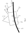
- FIG. 1 is an instrument for displaying the speed shown, which is used in instrument panels of motor vehicles.
- the instrument has a front of a scale 1 movable pointer 2, which is illuminated in a known manner.
- the instrument has a guide 3 designed as a shaft, wherein the pointer 2 along the guide of an electrically controllable drive 4 in the forward and backward directions is linearly movable.
- the drive 4 is connected via thin wires 5 to a power source 6.
- the drive is in this case a piezomotor, which moves along the stationary and guide 3, wherein the piezomotor with a drive member 7 frictionally engages the guide 3.
- the piezomotor has a carriage 8, which is forcibly guided with rollers 9 along the guide 3.
- the guide 3 is formed by a rod made of plastic interspersed with carbon, on which the piezomotor rests, wherein the piezo motor has a drive member with vibrating element 7, which acts on the rod 3 and the tip is excited to elliptical movements (arrow A) and thus repels the rod 3.
- a piezoceramic 10 is mounted, which is energized via an applied AC voltage.
- the vibrating element 7 is held by means of a spring 11 on the carriage 8.
Landscapes
- Physics & Mathematics (AREA)
- General Physics & Mathematics (AREA)
- Instrument Panels (AREA)
- Indicating Measured Values (AREA)
- General Electrical Machinery Utilizing Piezoelectricity, Electrostriction Or Magnetostriction (AREA)
- Valve Device For Special Equipments (AREA)
- Crystals, And After-Treatments Of Crystals (AREA)
Claims (10)
- Instrument indicateur analogique pour l'utilisation dans des tableaux de bord de véhicules automobiles, dans lequel l'instrument présente une aiguille indicatrice (2) déplaçable devant une échelle (1), l'aiguille indicatrice (2) pouvant être déplacée linéairement par un entraînement à commande électrique (4), vers l'avant et vers l'arrière le long d'un guide (3) réalisé sous forme de droite ou de courbe, l'aiguille indicatrice (2) étant disposée sur un chariot (8) guidé par force le long du guide (3), qui peut être déplacé directement par l'entraînement (4) reposant également sur le chariot (8), l'entraînement étant un entraînement linéaire, caractérisé en ce que
l'entraînement linéaire (4) est un moteur piézoélectrique qui se déplace le long du guide fixe (3), le moteur piézoélectrique venant en prise avec une partie d'entraînement (7) par engagement par force avec le guide (3). - Instrument selon la revendication 1, caractérisé en ce que le guide (3) est une barre, sur laquelle repose le moteur piézoélectrique, le moteur piézoélectrique présentant une partie d'entraînement avec un élément de vibration (7) qui vient en prise avec la barre et qui bute contre la barre par des mouvements elliptiques.
- Instrument selon la revendication 1 ou 2, caractérisé en ce que la position du chariot (8) ou de l'aiguille indicatrice (2) par rapport au guide (3) et donc par rapport à l'échelle (1) peut être établie avec un système de capteurs.
- Instrument selon la revendication 3, caractérisé en ce qu'une trace électriquement conductrice ayant une résistance homogène est montée le long du guide (3), sur laquelle repose un collecteur de courant du chariot (8), une tension maximale s'appliquant sur la longueur de la trace entre une position de départ et une position maximale du chariot, et une tension partielle pouvant être prélevée par le biais du collecteur de courant.
- Instrument selon la revendication 4, caractérisé en ce que les extrémités de la trace et la prise par le collecteur de courant sont montées dans le sens d'un pont de mesure, à partir duquel la position du collecteur de courant sur la trace et donc la position instantanée de l'aiguille indicatrice (2) par rapport à l'échelle (1) peuvent être calculées.
- Instrument selon la revendication 4, caractérisé en ce que l'entraînement (4) est un entraînement linéaire en forme de moteur piézoélectrique, et en ce que le guide (3) est une barre, sur laquelle repose le moteur piézoélectrique, le moteur piézoélectrique présentant une partie d'entraînement avec un élément de vibration (7), qui vient en prise sur la barre par engagement par force, et qui bute contre la barre par des mouvements elliptiques.
- Instrument selon la revendication 6, caractérisé en ce que la tension partielle est reprise par l'élément de vibration (7) s'appliquant avec contact contre la trace.
- Instrument selon l'une quelconque des revendications précédentes, caractérisé par un circuit de réglage, qui prédéfinit la position instantanée de l'aiguille indicatrice en tant que valeur d'entrée à un régulateur, qui la met en relation avec une position de consigne prédéfinie, le régulateur prédéfinissant la différence de régulation en tant que valeur de sortie pour le moteur piézoélectrique.
- Instrument selon l'une quelconque des revendications précédentes, caractérisé par un réglage à zéro qui effectue un ajustement lorsque l'aiguille indicatrice (2) se trouve dans sa position de départ.
- Instrument selon la revendication 2 ou 6,
caractérisé en ce que le guide, notamment la barre, se compose d'un matériau conducteur, en particulier d'un plastique renforcé de carbone.
Applications Claiming Priority (2)
| Application Number | Priority Date | Filing Date | Title |
|---|---|---|---|
| DE10325793A DE10325793A1 (de) | 2003-06-05 | 2003-06-05 | Linearzeiger |
| PCT/EP2004/006050 WO2004109233A2 (fr) | 2003-06-05 | 2004-06-04 | Aiguille indicatrice a mouvement lineaire |
Publications (2)
| Publication Number | Publication Date |
|---|---|
| EP1634040A2 EP1634040A2 (fr) | 2006-03-15 |
| EP1634040B1 true EP1634040B1 (fr) | 2010-04-07 |
Family
ID=33482665
Family Applications (1)
| Application Number | Title | Priority Date | Filing Date |
|---|---|---|---|
| EP04739604A Expired - Lifetime EP1634040B1 (fr) | 2003-06-05 | 2004-06-04 | Aiguille indicatrice a mouvement lineaire |
Country Status (6)
| Country | Link |
|---|---|
| US (1) | US20070194901A1 (fr) |
| EP (1) | EP1634040B1 (fr) |
| JP (1) | JP2006527360A (fr) |
| AT (1) | ATE463719T1 (fr) |
| DE (2) | DE10325793A1 (fr) |
| WO (1) | WO2004109233A2 (fr) |
Families Citing this family (10)
| Publication number | Priority date | Publication date | Assignee | Title |
|---|---|---|---|---|
| JP4719023B2 (ja) | 2006-02-10 | 2011-07-06 | 矢崎総業株式会社 | メータ |
| JP5139709B2 (ja) * | 2007-04-16 | 2013-02-06 | 矢崎総業株式会社 | 指針体駆動装置および指針式計器 |
| US20090040036A1 (en) * | 2007-07-18 | 2009-02-12 | Yefin Talis | Vehicular warning system and method of signage |
| DE102008062241A1 (de) * | 2008-02-01 | 2009-08-27 | Johnson Controls Gmbh | Zeiger-Anzeigeeinrichtung in einem Kraftfahrzeug |
| JP5247248B2 (ja) * | 2008-06-05 | 2013-07-24 | 矢崎総業株式会社 | 指針移動装置 |
| JP5396221B2 (ja) * | 2008-10-03 | 2014-01-22 | 矢崎総業株式会社 | 表示装置 |
| GB2478111B (en) * | 2010-02-19 | 2014-03-26 | Visteon Global Tech Inc | Gauge |
| DE102011054848B4 (de) * | 2011-10-27 | 2014-06-26 | Deutsches Zentrum für Luft- und Raumfahrt e.V. | Steuer- und Überwachungseinrichtung für Fahrzeuge |
| DE102013019565B4 (de) * | 2013-11-22 | 2019-07-04 | Audi Ag | Kombiinstrument |
| DE102019203440B3 (de) * | 2019-03-13 | 2020-04-02 | Audi Ag | Anzeigeinstrument für ein Kraftfahrzeug, Kraftfahrzeug mit einem entsprechenden Anzeigeinstrument sowie Verfahren zum Betreiben des Anzeigeinstruments |
Family Cites Families (29)
| Publication number | Priority date | Publication date | Assignee | Title |
|---|---|---|---|---|
| DE7429052U (de) * | 1975-01-30 | Gossen Gmbh | Markierungszeiger für Meßinstrumente | |
| DE625862C (de) * | 1934-06-13 | 1936-02-17 | Georg Schoenwald | Neigungswaage mit gleichmaessig geteilter Skala |
| US2097928A (en) * | 1935-03-25 | 1937-11-02 | Allg Elek Citats Ges Friedrick | Cord tensioning device for tuning means |
| FR822064A (fr) * | 1936-05-29 | 1937-12-20 | Siemens Ag | Système de guidage des index pour les cadrans de radiorécepteurs et analogues |
| BE458294A (fr) * | 1945-03-03 | |||
| US2538188A (en) * | 1945-11-14 | 1951-01-16 | Northern Engraving & Mfg Co | Indicator mechanism |
| US2529833A (en) * | 1946-08-27 | 1950-11-14 | Northern Engraving & Mfg Co | Indicator mechanism |
| US2529832A (en) * | 1946-08-27 | 1950-11-14 | Northern Engraving & Mfg Co | Indicator mechanism |
| US2521564A (en) * | 1946-10-24 | 1950-09-05 | Du Mont Allen B Lab Inc | Reversible pointer and scale indicator |
| US2905139A (en) * | 1957-10-16 | 1959-09-22 | Nat Screw & Mfg Company | Indicators |
| DE1873342U (de) * | 1961-06-13 | 1963-06-06 | Borletti Spa | Vorrichtung zur anzeige veraenderlicher groessen. |
| FR1587538A (fr) * | 1968-10-17 | 1970-03-20 | ||
| DE3609605A1 (de) * | 1986-03-21 | 1987-09-24 | Festo Kg | Linearmotor |
| DE3718835A1 (de) * | 1987-06-05 | 1988-12-15 | Roland Dipl Ing Knauer | Uhr |
| JPH0238924A (ja) * | 1988-07-29 | 1990-02-08 | Yazaki Corp | 計器のモータコントロール回路 |
| JPH0317602U (fr) * | 1989-06-30 | 1991-02-21 | ||
| JP2667251B2 (ja) * | 1989-06-27 | 1997-10-27 | アルプス電気株式会社 | 車載電装品の駆動制御装置 |
| US5285134A (en) * | 1990-03-09 | 1994-02-08 | Canon Kabushiki Kaisha | Control device for vibration type motor |
| IT1244953B (it) * | 1991-03-27 | 1994-09-13 | Carlo Ferrara | Sistema per il movimento di lancette di orologio. |
| JP2848499B2 (ja) * | 1991-03-28 | 1999-01-20 | 矢崎総業株式会社 | 車両用表示装置 |
| FR2679998A1 (fr) * | 1991-07-31 | 1993-02-05 | Peugeot | Dispositif de visualisation simultanee des valeurs de mesure de deux parametres. |
| CH685660B5 (fr) * | 1992-09-09 | 1996-03-15 | Asulab Sa | Piece d'horlogerie pourvue de moyens d'entraînement formes par un moteur piezo-electrique. |
| US5765501A (en) * | 1996-06-03 | 1998-06-16 | Taiwan Semiconductor Manufacturing Company, Ltd. | Marker for scale of an indicator |
| US6084363A (en) * | 1997-01-17 | 2000-07-04 | Minolta Co., Ltd. | Drive pulse generating apparatus for drive device using electromechanical transducer |
| DE19849161A1 (de) * | 1998-10-26 | 2000-05-18 | Mannesmann Vdo Ag | Zeigerinstrument |
| FR2790552B1 (fr) * | 1999-03-04 | 2001-05-25 | Magneti Marelli France | Indicateur perfectionne pour vehicule automobile |
| DE10134365A1 (de) * | 2001-07-14 | 2003-01-23 | Bosch Gmbh Robert | Anzeigevorrichtung |
| US6741184B1 (en) * | 2002-01-11 | 2004-05-25 | Delphi Technologies, Inc. | Pointer position detection using light emitting diodes |
| JP4719023B2 (ja) * | 2006-02-10 | 2011-07-06 | 矢崎総業株式会社 | メータ |
-
2003
- 2003-06-05 DE DE10325793A patent/DE10325793A1/de not_active Withdrawn
-
2004
- 2004-06-04 WO PCT/EP2004/006050 patent/WO2004109233A2/fr not_active Ceased
- 2004-06-04 EP EP04739604A patent/EP1634040B1/fr not_active Expired - Lifetime
- 2004-06-04 DE DE502004011000T patent/DE502004011000D1/de not_active Expired - Lifetime
- 2004-06-04 US US10/559,492 patent/US20070194901A1/en not_active Abandoned
- 2004-06-04 JP JP2006508278A patent/JP2006527360A/ja active Pending
- 2004-06-04 AT AT04739604T patent/ATE463719T1/de not_active IP Right Cessation
Also Published As
| Publication number | Publication date |
|---|---|
| ATE463719T1 (de) | 2010-04-15 |
| WO2004109233A3 (fr) | 2005-02-10 |
| JP2006527360A (ja) | 2006-11-30 |
| US20070194901A1 (en) | 2007-08-23 |
| WO2004109233A2 (fr) | 2004-12-16 |
| DE502004011000D1 (de) | 2010-05-20 |
| EP1634040A2 (fr) | 2006-03-15 |
| DE10325793A1 (de) | 2004-12-30 |
Similar Documents
| Publication | Publication Date | Title |
|---|---|---|
| DE102013013694B3 (de) | Anzeigeeinrichtung für ein Kraftfahrzeug | |
| EP1634040B1 (fr) | Aiguille indicatrice a mouvement lineaire | |
| EP2920665B1 (fr) | Dispositif de commande pour un appareil de véhicule | |
| EP1917167B1 (fr) | Dispositif d'entrainement auxiliaire electromoteur pour des vehicules a moteur | |
| DE102012106846A1 (de) | Mikrotom mit einem Piezolinearantrieb | |
| DE102011005370A1 (de) | Hebelbetätigungsvorrichtung | |
| DE2627865A1 (de) | Fuellstands-messeinrichtung | |
| EP1182767B1 (fr) | Guidage linéaire | |
| DE102007038475A1 (de) | Kraftfahrzeuganzeige | |
| EP1625362A1 (fr) | Commande incrementale | |
| EP2891024A1 (fr) | Appareil de commande pour un dispositif fonctionnel d'un véhicule à moteur | |
| DE102019113296A1 (de) | Zweiachspositioniervorrichtung | |
| DE2646534A1 (de) | Kartengeraet | |
| DE102006024680B4 (de) | Positionsmeßvorrichtung | |
| DE102018115682A1 (de) | Spindellinearverstellantrieb | |
| DE19524907A1 (de) | Rastersondenmikroskop | |
| DE102018203409A1 (de) | Linearbewegungsvorrichtung und Verfahren | |
| WO1999018413A1 (fr) | Mecanisme de mesure, notamment pour dispositif indicateur utilise dans la technique de l'automobile | |
| DE534872C (de) | Vorrichtung zum Begrenzen der Geschwindigkeit | |
| DE1275592B (de) | Vorrichtung zur Erzeugung zweier gegeneinander phasenverschobener elektrischer Signale | |
| EP0433566A1 (fr) | Dispositif d'actionnement d'un organe de réglage | |
| DE102005010073A1 (de) | Elektromechanisches Präzisions-Antriebssystem | |
| DE20216628U1 (de) | Zeitanzeige | |
| DD294778A5 (de) | Anordnung zur messbereichserweiterung absoluter laengenmesssysteme | |
| DE102022104406A1 (de) | Kraftfahrzeuginnenverkleidungsteil sowie Verfahren zum Herstellen eines Kraftfahrzeuginnenverkleidungsteils |
Legal Events
| Date | Code | Title | Description |
|---|---|---|---|
| PUAI | Public reference made under article 153(3) epc to a published international application that has entered the european phase |
Free format text: ORIGINAL CODE: 0009012 |
|
| 17P | Request for examination filed |
Effective date: 20060105 |
|
| AK | Designated contracting states |
Kind code of ref document: A2 Designated state(s): AT BE BG CH CY CZ DE DK EE ES FI FR GB GR HU IE IT LI LU MC NL PL PT RO SE SI SK TR |
|
| DAX | Request for extension of the european patent (deleted) | ||
| 17Q | First examination report despatched |
Effective date: 20060314 |
|
| RAP1 | Party data changed (applicant data changed or rights of an application transferred) |
Owner name: JOHNSON CONTROLS AUTOMOTIVE ELECTRONICS GMBH |
|
| GRAP | Despatch of communication of intention to grant a patent |
Free format text: ORIGINAL CODE: EPIDOSNIGR1 |
|
| GRAS | Grant fee paid |
Free format text: ORIGINAL CODE: EPIDOSNIGR3 |
|
| GRAA | (expected) grant |
Free format text: ORIGINAL CODE: 0009210 |
|
| AK | Designated contracting states |
Kind code of ref document: B1 Designated state(s): AT BE BG CH CY CZ DE DK EE ES FI FR GB GR HU IE IT LI LU MC NL PL PT RO SE SI SK TR |
|
| REG | Reference to a national code |
Ref country code: GB Ref legal event code: FG4D Free format text: NOT ENGLISH |
|
| REG | Reference to a national code |
Ref country code: CH Ref legal event code: EP |
|
| REG | Reference to a national code |
Ref country code: IE Ref legal event code: FG4D Free format text: LANGUAGE OF EP DOCUMENT: GERMAN |
|
| REF | Corresponds to: |
Ref document number: 502004011000 Country of ref document: DE Date of ref document: 20100520 Kind code of ref document: P |
|
| REG | Reference to a national code |
Ref country code: NL Ref legal event code: VDEP Effective date: 20100407 |
|
| PG25 | Lapsed in a contracting state [announced via postgrant information from national office to epo] |
Ref country code: SI Free format text: LAPSE BECAUSE OF FAILURE TO SUBMIT A TRANSLATION OF THE DESCRIPTION OR TO PAY THE FEE WITHIN THE PRESCRIBED TIME-LIMIT Effective date: 20100407 |
|
| REG | Reference to a national code |
Ref country code: IE Ref legal event code: FD4D |
|
| PG25 | Lapsed in a contracting state [announced via postgrant information from national office to epo] |
Ref country code: ES Free format text: LAPSE BECAUSE OF FAILURE TO SUBMIT A TRANSLATION OF THE DESCRIPTION OR TO PAY THE FEE WITHIN THE PRESCRIBED TIME-LIMIT Effective date: 20100718 Ref country code: SE Free format text: LAPSE BECAUSE OF FAILURE TO SUBMIT A TRANSLATION OF THE DESCRIPTION OR TO PAY THE FEE WITHIN THE PRESCRIBED TIME-LIMIT Effective date: 20100407 Ref country code: NL Free format text: LAPSE BECAUSE OF FAILURE TO SUBMIT A TRANSLATION OF THE DESCRIPTION OR TO PAY THE FEE WITHIN THE PRESCRIBED TIME-LIMIT Effective date: 20100407 |
|
| PG25 | Lapsed in a contracting state [announced via postgrant information from national office to epo] |
Ref country code: FI Free format text: LAPSE BECAUSE OF FAILURE TO SUBMIT A TRANSLATION OF THE DESCRIPTION OR TO PAY THE FEE WITHIN THE PRESCRIBED TIME-LIMIT Effective date: 20100407 |
|
| BERE | Be: lapsed |
Owner name: JOHNSON CONTROLS AUTOMOTIVE ELECTRONICS G.M.B.H. Effective date: 20100630 |
|
| PG25 | Lapsed in a contracting state [announced via postgrant information from national office to epo] |
Ref country code: CY Free format text: LAPSE BECAUSE OF FAILURE TO SUBMIT A TRANSLATION OF THE DESCRIPTION OR TO PAY THE FEE WITHIN THE PRESCRIBED TIME-LIMIT Effective date: 20100428 Ref country code: PL Free format text: LAPSE BECAUSE OF FAILURE TO SUBMIT A TRANSLATION OF THE DESCRIPTION OR TO PAY THE FEE WITHIN THE PRESCRIBED TIME-LIMIT Effective date: 20100407 Ref country code: GR Free format text: LAPSE BECAUSE OF FAILURE TO SUBMIT A TRANSLATION OF THE DESCRIPTION OR TO PAY THE FEE WITHIN THE PRESCRIBED TIME-LIMIT Effective date: 20100708 |
|
| PG25 | Lapsed in a contracting state [announced via postgrant information from national office to epo] |
Ref country code: IE Free format text: LAPSE BECAUSE OF FAILURE TO SUBMIT A TRANSLATION OF THE DESCRIPTION OR TO PAY THE FEE WITHIN THE PRESCRIBED TIME-LIMIT Effective date: 20100407 Ref country code: DK Free format text: LAPSE BECAUSE OF FAILURE TO SUBMIT A TRANSLATION OF THE DESCRIPTION OR TO PAY THE FEE WITHIN THE PRESCRIBED TIME-LIMIT Effective date: 20100407 Ref country code: EE Free format text: LAPSE BECAUSE OF FAILURE TO SUBMIT A TRANSLATION OF THE DESCRIPTION OR TO PAY THE FEE WITHIN THE PRESCRIBED TIME-LIMIT Effective date: 20100407 Ref country code: MC Free format text: LAPSE BECAUSE OF NON-PAYMENT OF DUE FEES Effective date: 20100630 Ref country code: PT Free format text: LAPSE BECAUSE OF FAILURE TO SUBMIT A TRANSLATION OF THE DESCRIPTION OR TO PAY THE FEE WITHIN THE PRESCRIBED TIME-LIMIT Effective date: 20100809 |
|
| REG | Reference to a national code |
Ref country code: CH Ref legal event code: PL |
|
| PLBE | No opposition filed within time limit |
Free format text: ORIGINAL CODE: 0009261 |
|
| STAA | Information on the status of an ep patent application or granted ep patent |
Free format text: STATUS: NO OPPOSITION FILED WITHIN TIME LIMIT |
|
| PG25 | Lapsed in a contracting state [announced via postgrant information from national office to epo] |
Ref country code: CZ Free format text: LAPSE BECAUSE OF FAILURE TO SUBMIT A TRANSLATION OF THE DESCRIPTION OR TO PAY THE FEE WITHIN THE PRESCRIBED TIME-LIMIT Effective date: 20100407 Ref country code: SK Free format text: LAPSE BECAUSE OF FAILURE TO SUBMIT A TRANSLATION OF THE DESCRIPTION OR TO PAY THE FEE WITHIN THE PRESCRIBED TIME-LIMIT Effective date: 20100407 Ref country code: RO Free format text: LAPSE BECAUSE OF FAILURE TO SUBMIT A TRANSLATION OF THE DESCRIPTION OR TO PAY THE FEE WITHIN THE PRESCRIBED TIME-LIMIT Effective date: 20100407 |
|
| 26N | No opposition filed |
Effective date: 20110110 |
|
| REG | Reference to a national code |
Ref country code: FR Ref legal event code: ST Effective date: 20110228 |
|
| GBPC | Gb: european patent ceased through non-payment of renewal fee |
Effective date: 20100707 |
|
| PG25 | Lapsed in a contracting state [announced via postgrant information from national office to epo] |
Ref country code: IT Free format text: LAPSE BECAUSE OF FAILURE TO SUBMIT A TRANSLATION OF THE DESCRIPTION OR TO PAY THE FEE WITHIN THE PRESCRIBED TIME-LIMIT Effective date: 20100407 |
|
| PG25 | Lapsed in a contracting state [announced via postgrant information from national office to epo] |
Ref country code: LI Free format text: LAPSE BECAUSE OF NON-PAYMENT OF DUE FEES Effective date: 20100630 Ref country code: CH Free format text: LAPSE BECAUSE OF NON-PAYMENT OF DUE FEES Effective date: 20100630 |
|
| PG25 | Lapsed in a contracting state [announced via postgrant information from national office to epo] |
Ref country code: FR Free format text: LAPSE BECAUSE OF NON-PAYMENT OF DUE FEES Effective date: 20100630 |
|
| PG25 | Lapsed in a contracting state [announced via postgrant information from national office to epo] |
Ref country code: BE Free format text: LAPSE BECAUSE OF NON-PAYMENT OF DUE FEES Effective date: 20100630 |
|
| PG25 | Lapsed in a contracting state [announced via postgrant information from national office to epo] |
Ref country code: GB Free format text: LAPSE BECAUSE OF NON-PAYMENT OF DUE FEES Effective date: 20100707 |
|
| PG25 | Lapsed in a contracting state [announced via postgrant information from national office to epo] |
Ref country code: AT Free format text: LAPSE BECAUSE OF NON-PAYMENT OF DUE FEES Effective date: 20100604 |
|
| PG25 | Lapsed in a contracting state [announced via postgrant information from national office to epo] |
Ref country code: HU Free format text: LAPSE BECAUSE OF FAILURE TO SUBMIT A TRANSLATION OF THE DESCRIPTION OR TO PAY THE FEE WITHIN THE PRESCRIBED TIME-LIMIT Effective date: 20101008 Ref country code: BG Free format text: LAPSE BECAUSE OF FAILURE TO SUBMIT A TRANSLATION OF THE DESCRIPTION OR TO PAY THE FEE WITHIN THE PRESCRIBED TIME-LIMIT Effective date: 20100407 Ref country code: LU Free format text: LAPSE BECAUSE OF NON-PAYMENT OF DUE FEES Effective date: 20100604 |
|
| PG25 | Lapsed in a contracting state [announced via postgrant information from national office to epo] |
Ref country code: TR Free format text: LAPSE BECAUSE OF FAILURE TO SUBMIT A TRANSLATION OF THE DESCRIPTION OR TO PAY THE FEE WITHIN THE PRESCRIBED TIME-LIMIT Effective date: 20100407 |
|
| PG25 | Lapsed in a contracting state [announced via postgrant information from national office to epo] |
Ref country code: BG Free format text: LAPSE BECAUSE OF FAILURE TO SUBMIT A TRANSLATION OF THE DESCRIPTION OR TO PAY THE FEE WITHIN THE PRESCRIBED TIME-LIMIT Effective date: 20100707 |
|
| PGFP | Annual fee paid to national office [announced via postgrant information from national office to epo] |
Ref country code: DE Payment date: 20180625 Year of fee payment: 15 |
|
| REG | Reference to a national code |
Ref country code: DE Ref legal event code: R119 Ref document number: 502004011000 Country of ref document: DE |
|
| PG25 | Lapsed in a contracting state [announced via postgrant information from national office to epo] |
Ref country code: DE Free format text: LAPSE BECAUSE OF NON-PAYMENT OF DUE FEES Effective date: 20200101 |