EP1634545B1 - Zahnärztliches Wasserheizgerät - Google Patents
Zahnärztliches Wasserheizgerät Download PDFInfo
- Publication number
- EP1634545B1 EP1634545B1 EP05019987A EP05019987A EP1634545B1 EP 1634545 B1 EP1634545 B1 EP 1634545B1 EP 05019987 A EP05019987 A EP 05019987A EP 05019987 A EP05019987 A EP 05019987A EP 1634545 B1 EP1634545 B1 EP 1634545B1
- Authority
- EP
- European Patent Office
- Prior art keywords
- water
- water channel
- heater
- dental
- outlet
- Prior art date
- Legal status (The legal status is an assumption and is not a legal conclusion. Google has not performed a legal analysis and makes no representation as to the accuracy of the status listed.)
- Expired - Lifetime
Links
Images
Classifications
-
- A—HUMAN NECESSITIES
- A61—MEDICAL OR VETERINARY SCIENCE; HYGIENE
- A61C—DENTISTRY; APPARATUS OR METHODS FOR ORAL OR DENTAL HYGIENE
- A61C1/00—Dental machines for boring or cutting ; General features of dental machines or apparatus, e.g. hand-piece design
- A61C1/0061—Air and water supply systems; Valves specially adapted therefor
- A61C1/0069—Fluid temperature control
-
- F—MECHANICAL ENGINEERING; LIGHTING; HEATING; WEAPONS; BLASTING
- F24—HEATING; RANGES; VENTILATING
- F24H—FLUID HEATERS, e.g. WATER OR AIR HEATERS, HAVING HEAT-GENERATING MEANS, e.g. HEAT PUMPS, IN GENERAL
- F24H1/00—Water heaters, e.g. boilers, continuous-flow heaters or water-storage heaters
- F24H1/10—Continuous-flow heaters, i.e. heaters in which heat is generated only while the water is flowing, e.g. with direct contact of the water with the heating medium
- F24H1/12—Continuous-flow heaters, i.e. heaters in which heat is generated only while the water is flowing, e.g. with direct contact of the water with the heating medium in which the water is kept separate from the heating medium
- F24H1/14—Continuous-flow heaters, i.e. heaters in which heat is generated only while the water is flowing, e.g. with direct contact of the water with the heating medium in which the water is kept separate from the heating medium by tubes, e.g. bent in serpentine form
- F24H1/16—Continuous-flow heaters, i.e. heaters in which heat is generated only while the water is flowing, e.g. with direct contact of the water with the heating medium in which the water is kept separate from the heating medium by tubes, e.g. bent in serpentine form helically or spirally coiled
- F24H1/162—Continuous-flow heaters, i.e. heaters in which heat is generated only while the water is flowing, e.g. with direct contact of the water with the heating medium in which the water is kept separate from the heating medium by tubes, e.g. bent in serpentine form helically or spirally coiled using electrical energy supply
Definitions
- the dental water heater of the present invention while the water supplied through the inlet is passed through the entire length of the whole water channel, the water is warmed with the heat from the heating means, and taken out through the outlet. Since the whole water channel is formed of a plurality of water channel sections each extending spirally and arranged in layers, a relatively long water channel may be formed in the body of a relatively small volume. This secures sufficient length of way (duration) for the water to receive heat from the heating means, and remarkably improves heat efficiency of a dental water heater.
- the inlet for water may be provided in the water channel section of the outermost layer, and the outlet for water may be provided in the water channel section of the innermost layer.
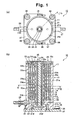
- the whole water channel formed of the water channel sections 13 to 16 is provided with at least one inlet and at least one outlet for the water to be heated, so that the water is supplied through the inlet, flows through the entire length of the whole water channel, and taken out through the outlet as warmed water.
- the first water channel defining member 22 has at least one communication port 22b penetrating the member 22 in the upper end portion of the spiral channel 22a, and similarly, the third water channel defining member 24 has at least one communication port 24b penetrating the member 24 in the upper end portion of the spiral channel 24a.
- the second water channel defining member 23 has at least one communication port 23b penetrating the member 23 in the lower end portion of the spiral channel 23a.
- the first water channel section 13 communicates with the second water channel section 14 via the first communication ports 22b in the upper end portion thereof, the second water channel section 14 communicates with the third water channel section 15 via the second communication ports 23b in the lower end portion thereof, and the third water channel section 15 communicates with the fourth water channel section 16 via the third communication ports 24b in the upper end portion thereof.
- the first to fourth water channel sections 13 to 16 thus communicated together form a whole water channel.
- the cylindrical portion 25b of the fourth water channel defining member 25 receives the heater 12 inserted therein, which is fixed therein with an adhesive, and the top of the portion 25b is closed with lid 34. Electric cables 35 connected to the heater 12 extend through the lid 34 to outside.
- the flow pathway of water to be heated in the dental water heater 10 is explained below.
- Water to be heated is supplied from an external source, such as a tap, and introduced into the dental water heater 10 through the hose connecting member 27.
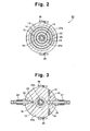
- the water taken in through the hose connecting member 27 is then passed through the attachment hole 29, branched into the transverse channels 30, passed up through the respective vertical channels 31 as shown in Fig. 3 , and led to the lower end portion of the first water channel section 13 as shown in Fig. 1(b) . From here, the water spirally rises through the first water channel section 13 up to the first communication ports 22b in the upper end portion thereof, through which it flows into the upper end portion of the second water channel section 14.
- the water then spirally descends through the second water channel section 14 down to the second communication ports 23b in the lower end portion thereof, through which it flows into the lower end portion of the third water channel section 15. Again, the water spirally rises through the third water channel section 15 up to the third communication ports 24b in the upper end portion thereof, through which it flows into the upper end portion of the fourth water channel section 16. Then the water spirally descends through the fourth water channel section 16 down to its lower end, passes through the fourth communication port 21d formed through the bottom portion 21b of the casing 21, up through the vertical channel 33, and through the attachment hole 32, and taken out through the hose connecting member 28 as warmed water. The warmed water thus discharged from the dental water heater 10 is then supplied to a dental treatment apparatus for spraying into the oral cavity of a patient.
- the first to third water channel defining members 22 to 24 are shown to have two communication ports 22b to 24b, respectively, and the fourth water channel defining member 25 is shown to have one communication port 21d, in the sectional view of Fig. 1 (b) .
- the first and third communication ports 22b and 24b are provided in the upper end portion of the first and third water channel defining members 22 and 24, respectively, and the second and fourth communication ports 23b and 21d are provided in the lower end portion of the second and fourth water channel defining members 23 and 25, respectively.
- the number and location of the first to fourth communication ports 22b to 24b and 21d may be selected as desired without departing from the present invention.
- the whole water channel is shown to have two inlets for water communicating with two vertical channels 31 and one outlet for water communicating with the vertical channel 33 in the drawings, and both the inlets and the outlet are provided in the lower end portions of the water channel sections 13 and 16, respectively.
- the number and location of the inlet and outlet may be selected as desired without departing from the present invention, and either of the inlet or outlet or both of them may be provided in the upper end portions of the water channel sections 13 and 16, respectively.
Landscapes
- Engineering & Computer Science (AREA)
- Health & Medical Sciences (AREA)
- Combustion & Propulsion (AREA)
- Oral & Maxillofacial Surgery (AREA)
- Physics & Mathematics (AREA)
- Mechanical Engineering (AREA)
- General Engineering & Computer Science (AREA)
- Water Supply & Treatment (AREA)
- Thermal Sciences (AREA)
- Chemical & Material Sciences (AREA)
- Dentistry (AREA)
- Epidemiology (AREA)
- Life Sciences & Earth Sciences (AREA)
- Animal Behavior & Ethology (AREA)
- General Health & Medical Sciences (AREA)
- Public Health (AREA)
- Veterinary Medicine (AREA)
- Dental Tools And Instruments Or Auxiliary Dental Instruments (AREA)
Claims (4)
- Ein zahnärztliches Wasserheizgerät (10) mit einem säulenartigen Körper (11), wobei der Körper (11) aufweist:ein Heizmittel (12), das sich in axialer Richtung des Körpers erstreckt, undeine Mehrzahl von Schichten von Wasserkanalabschnitten (13 bis 16), die um das Heizmittel (12) angeordnet sind, wobei jeder der Wasserkanalabschnitte (13 bis 16) sich spiralförmig in der axialen Richtung des Körpers erstreckt,wobei benachbarte Paare von Wasserkanalabschnitten (13-16) entweder am oberen oder unteren Endbereichen davon in Verbindung gebracht sind, um so gemeinsam einen Gesamt-Wasserkanal zu bilden,wobei der Gesamt-Wasserkanal einen Einlass und einen Auslass für zu erwärmendes Wasser aufweist, sodass Wasser durch den Einlass zugeführt wird, durch die gesamte Länge des Gesamt-Wasserkanals strömt und als erwärmtes Wasser durch den Auslass entnommen wird, undwobei der Einlass für Wasser im Wasserkanalabschnitt der äußersten Schicht (13) bereitgestellt ist und der Auslass für Wasser im Wasserkanalabschnitt der innersten Schicht (16) bereitgestellt ist.
- Das zahnärztliche Wasserheizgerät gemäß Patentanspruch 1, wobei die Mehrzahl von Schichten von Wasserkanalabschnitten (13 bis 16) so in Verbindung gebracht ist, dass Wasser, das der äußerste Schicht des Wasserkanalabschnitts (13) zugeführt wird, reihenweise in jede Schicht einwärts hin zur innersten Schicht des Wasserkanalabschnitts (16) strömt.
- Das zahnärztliche Wasserheizgerät gemäß Patentanspruch 1, wobei die Mehrzahl von Schichten von Wasserkanalabschnitten (13 bis 16) koaxial mit den Heizmitteln (12) sowie miteinander angeordnet ist.
- Das zahnärztliche Wasserheizgerät gemäß Patentanspruch 1, wobei benachbarte Paare von Wasserkanalabschnitten (13 bis 16) durch mindestens einen Verbindungsanschluss (22b, 23b, 24b) in Verbindung gebracht sind.
Applications Claiming Priority (1)
| Application Number | Priority Date | Filing Date | Title |
|---|---|---|---|
| JP2004267060A JP3974908B2 (ja) | 2004-09-14 | 2004-09-14 | 歯科用温水器 |
Publications (2)
| Publication Number | Publication Date |
|---|---|
| EP1634545A1 EP1634545A1 (de) | 2006-03-15 |
| EP1634545B1 true EP1634545B1 (de) | 2011-11-30 |
Family
ID=35455862
Family Applications (1)
| Application Number | Title | Priority Date | Filing Date |
|---|---|---|---|
| EP05019987A Expired - Lifetime EP1634545B1 (de) | 2004-09-14 | 2005-09-14 | Zahnärztliches Wasserheizgerät |
Country Status (6)
| Country | Link |
|---|---|
| US (1) | US7248792B2 (de) |
| EP (1) | EP1634545B1 (de) |
| JP (1) | JP3974908B2 (de) |
| KR (1) | KR101143327B1 (de) |
| AT (1) | ATE535206T1 (de) |
| TW (1) | TW200612870A (de) |
Families Citing this family (15)
| Publication number | Priority date | Publication date | Assignee | Title |
|---|---|---|---|---|
| US7471882B2 (en) * | 2005-09-16 | 2008-12-30 | Welker, Inc. | Heated regulator with removable heat inducer and fluid heater and methods of use |
| US20100046934A1 (en) * | 2008-08-19 | 2010-02-25 | Johnson Gregg C | High thermal transfer spiral flow heat exchanger |
| DE202010006739U1 (de) * | 2010-05-12 | 2010-08-19 | Türk & Hillinger GmbH | Durchlauferhitzer |
| DE202011107227U1 (de) | 2011-10-28 | 2011-11-09 | Türk & Hillinger GmbH | Durchlauferhitzer |
| WO2014073009A1 (en) * | 2012-11-09 | 2014-05-15 | Paolini Cristiano | System for dispensing beverages |
| US11002465B2 (en) * | 2014-09-24 | 2021-05-11 | Bestway Inflatables & Materials Corp. | PTC heater |
| CN105716225B (zh) * | 2014-12-22 | 2020-08-11 | 株式会社堀场Stec | 流体加热器、加热块和汽化系统 |
| ITUB20151864A1 (it) * | 2015-07-01 | 2017-01-01 | Tullio Ritrovato | Dispositivo per il riscaldamento di un fluido |
| CH711968A1 (de) * | 2015-12-28 | 2017-06-30 | C3 Casting Competence Center Gmbh | Durchlauferhitzer. |
| KR102447439B1 (ko) * | 2017-04-25 | 2022-09-27 | 엘지전자 주식회사 | 수처리 장치용 온수생성모듈 |
| WO2018206424A1 (en) * | 2017-05-10 | 2018-11-15 | Gea Food Solutions Weert B.V. | Improved heating means for a flow wrapper |
| GB2592093B (en) * | 2020-02-12 | 2022-03-16 | Singh Nagi Jaskiran | An electric boiler |
| US11092358B1 (en) * | 2020-02-14 | 2021-08-17 | Eberspächer Catem Gmbh & Co. Kg | Electrical heating device |
| JP7233635B1 (ja) | 2022-02-24 | 2023-03-07 | 株式会社エム・ディ・インスツルメンツ | 歯科用温水器 |
| JP7303972B1 (ja) | 2023-02-01 | 2023-07-06 | 株式会社エム・ディ・インスツルメンツ | 歯科用温水器 |
Family Cites Families (15)
| Publication number | Priority date | Publication date | Assignee | Title |
|---|---|---|---|---|
| NL44509C (de) | 1900-01-01 | |||
| US1356818A (en) * | 1917-07-11 | 1920-10-26 | Jr William S Hadaway | Heating apparatus |
| US1519395A (en) * | 1920-08-07 | 1924-12-16 | George H Sanburn | Water heater |
| US1671677A (en) * | 1927-03-14 | 1928-05-29 | Henry H Keeton | Electric water heater |
| US1724767A (en) * | 1928-04-13 | 1929-08-13 | Robert A Mercer | Dental water heater |
| US1716996A (en) * | 1928-06-16 | 1929-06-11 | Maria M Adam | Electric water heater |
| US1985830A (en) * | 1929-10-01 | 1934-12-25 | Hynes Lee Powers | Apparatus for treating fluid mediums |
| US2576558A (en) * | 1948-11-24 | 1951-11-27 | James A Bede | Paint heater |
| US3584194A (en) * | 1969-05-23 | 1971-06-08 | Aro Corp | Fluid heating techniques |
| US3835294A (en) * | 1973-04-06 | 1974-09-10 | Binks Mfg Co | High pressure electric fluid heater |
| FR2420726A1 (fr) * | 1978-03-21 | 1979-10-19 | Commissariat Energie Atomique | Dispositif pour porter un liquide a une temperature donnee |
| US4465922A (en) * | 1982-08-20 | 1984-08-14 | Nordson Corporation | Electric heater for heating high solids fluid coating materials |
| US4604515A (en) * | 1984-10-16 | 1986-08-05 | Cmr Enterprises, Inc. | Tankless electric water heater with staged heating element energization |
| US5265318A (en) * | 1991-06-02 | 1993-11-30 | Shero William K | Method for forming an in-line water heater having a spirally configured heat exchanger |
| US5257341A (en) * | 1992-06-19 | 1993-10-26 | A-Dec, Inc. | Compact in-line thermostatically controlled electric water heater for use with dental instruments |
-
2004
- 2004-09-14 JP JP2004267060A patent/JP3974908B2/ja not_active Expired - Fee Related
-
2005
- 2005-08-30 TW TW094129758A patent/TW200612870A/zh not_active IP Right Cessation
- 2005-09-13 KR KR1020050084937A patent/KR101143327B1/ko not_active Expired - Fee Related
- 2005-09-13 US US11/224,228 patent/US7248792B2/en not_active Expired - Fee Related
- 2005-09-14 EP EP05019987A patent/EP1634545B1/de not_active Expired - Lifetime
- 2005-09-14 AT AT05019987T patent/ATE535206T1/de active
Also Published As
| Publication number | Publication date |
|---|---|
| KR20060051226A (ko) | 2006-05-19 |
| TW200612870A (en) | 2006-05-01 |
| TWI356690B (de) | 2012-01-21 |
| US20060056571A1 (en) | 2006-03-16 |
| EP1634545A1 (de) | 2006-03-15 |
| US7248792B2 (en) | 2007-07-24 |
| ATE535206T1 (de) | 2011-12-15 |
| KR101143327B1 (ko) | 2012-05-09 |
| JP2006081612A (ja) | 2006-03-30 |
| JP3974908B2 (ja) | 2007-09-12 |
Similar Documents
| Publication | Publication Date | Title |
|---|---|---|
| EP1634545B1 (de) | Zahnärztliches Wasserheizgerät | |
| US6581224B2 (en) | Bed heating systems | |
| EP2322113B1 (de) | Nabe mit Doppelverschlusskammer | |
| US6705534B1 (en) | Shower control system | |
| US7334274B2 (en) | Swirling bathing tub | |
| AU2002364521A8 (en) | Resistive heater formed inside a fluid passage of a fluid vaporizing device | |
| CN106377159A (zh) | 电压力锅 | |
| EP2453194B1 (de) | Abwasserkanal ausgerüstet mit einem Wärmetauscher, und Duschwanne ausgerüstet mit solch einem Abwasserkanal | |
| ES2744594T3 (es) | Mezclador termostático externo, en particular para componentes higiénico-sanitarios, con una elevada seguridad contra el peligro de quemaduras por contacto | |
| KR20050057890A (ko) | 난방용 온수순환 매트 | |
| KR100852342B1 (ko) | 이중 가열 히터를 포함한 정수 가열시스템 | |
| KR101358122B1 (ko) | 매트용 냉·온수 순환 공급 장치 | |
| IT9021844A1 (it) | Apparecchio di riscaldamento a convezione radiante. | |
| KR200294627Y1 (ko) | 열에너지를 이용한 무동력 강제순환장치 및 그를 이용한온수매트 | |
| KR200370868Y1 (ko) | 세라믹히터를 이용한 순간온수장치 | |
| CN213362871U (zh) | 进出水装置及热水器 | |
| KR100505458B1 (ko) | 열에너지를 이용한 무동력 강제순환장치 및 그를 이용한온수매트 | |
| KR100889456B1 (ko) | 이중 가열 히터 및 이를 포함하는 냉온수 공급장치 | |
| KR200197729Y1 (ko) | 좌욕 찜질기 | |
| KR20210021912A (ko) | 온수 공급 장치 | |
| KR100714217B1 (ko) | 침대 온도조절용 수류관의 구조, 침대 온도조절 시스템 및온도조절이 가능한 침대 | |
| CN113865095B (zh) | 进出水装置及热水器 | |
| CN219480926U (zh) | 进食护理器 | |
| CN201481972U (zh) | 一种前置精确肠道给药装置 | |
| WO2019231394A1 (en) | An instant heater |
Legal Events
| Date | Code | Title | Description |
|---|---|---|---|
| PUAI | Public reference made under article 153(3) epc to a published international application that has entered the european phase |
Free format text: ORIGINAL CODE: 0009012 |
|
| AK | Designated contracting states |
Kind code of ref document: A1 Designated state(s): AT BE BG CH CY CZ DE DK EE ES FI FR GB GR HU IE IS IT LI LT LU LV MC NL PL PT RO SE SI SK TR |
|
| AX | Request for extension of the european patent |
Extension state: AL BA HR MK YU |
|
| 17P | Request for examination filed |
Effective date: 20060719 |
|
| 17Q | First examination report despatched |
Effective date: 20060828 |
|
| AKX | Designation fees paid |
Designated state(s): AT CH DE FR GB IT LI |
|
| GRAP | Despatch of communication of intention to grant a patent |
Free format text: ORIGINAL CODE: EPIDOSNIGR1 |
|
| GRAS | Grant fee paid |
Free format text: ORIGINAL CODE: EPIDOSNIGR3 |
|
| GRAA | (expected) grant |
Free format text: ORIGINAL CODE: 0009210 |
|
| AK | Designated contracting states |
Kind code of ref document: B1 Designated state(s): AT CH DE FR GB IT LI |
|
| REG | Reference to a national code |
Ref country code: GB Ref legal event code: FG4D Ref country code: CH Ref legal event code: EP |
|
| REG | Reference to a national code |
Ref country code: CH Ref legal event code: NV Representative=s name: KATZAROV S.A. |
|
| REG | Reference to a national code |
Ref country code: DE Ref legal event code: R096 Ref document number: 602005031431 Country of ref document: DE Effective date: 20120126 |
|
| PLBE | No opposition filed within time limit |
Free format text: ORIGINAL CODE: 0009261 |
|
| STAA | Information on the status of an ep patent application or granted ep patent |
Free format text: STATUS: NO OPPOSITION FILED WITHIN TIME LIMIT |
|
| 26N | No opposition filed |
Effective date: 20120831 |
|
| REG | Reference to a national code |
Ref country code: DE Ref legal event code: R097 Ref document number: 602005031431 Country of ref document: DE Effective date: 20120831 |
|
| REG | Reference to a national code |
Ref country code: CH Ref legal event code: PL |
|
| GBPC | Gb: european patent ceased through non-payment of renewal fee |
Effective date: 20120914 |
|
| PG25 | Lapsed in a contracting state [announced via postgrant information from national office to epo] |
Ref country code: GB Free format text: LAPSE BECAUSE OF NON-PAYMENT OF DUE FEES Effective date: 20120914 Ref country code: CH Free format text: LAPSE BECAUSE OF NON-PAYMENT OF DUE FEES Effective date: 20120930 Ref country code: LI Free format text: LAPSE BECAUSE OF NON-PAYMENT OF DUE FEES Effective date: 20120930 |
|
| PG25 | Lapsed in a contracting state [announced via postgrant information from national office to epo] |
Ref country code: IT Free format text: LAPSE BECAUSE OF NON-PAYMENT OF DUE FEES Effective date: 20120914 |
|
| REG | Reference to a national code |
Ref country code: AT Ref legal event code: MM01 Ref document number: 535206 Country of ref document: AT Kind code of ref document: T Effective date: 20120914 |
|
| PG25 | Lapsed in a contracting state [announced via postgrant information from national office to epo] |
Ref country code: AT Free format text: LAPSE BECAUSE OF NON-PAYMENT OF DUE FEES Effective date: 20120914 |
|
| REG | Reference to a national code |
Ref country code: DE Ref legal event code: R082 Ref document number: 602005031431 Country of ref document: DE Representative=s name: BOCKHORNI & KOLLEGEN PATENT- UND RECHTSANWAELT, DE Ref country code: DE Ref legal event code: R082 Ref document number: 602005031431 Country of ref document: DE Representative=s name: HEYER, VOLKER, DIPL.-PHYS. DR.RER.NAT., DE |
|
| REG | Reference to a national code |
Ref country code: DE Ref legal event code: R082 Ref document number: 602005031431 Country of ref document: DE Representative=s name: HEYER, VOLKER, DIPL.-PHYS. DR.RER.NAT., DE |
|
| PGFP | Annual fee paid to national office [announced via postgrant information from national office to epo] |
Ref country code: DE Payment date: 20141121 Year of fee payment: 10 Ref country code: FR Payment date: 20140908 Year of fee payment: 10 |
|
| REG | Reference to a national code |
Ref country code: DE Ref legal event code: R119 Ref document number: 602005031431 Country of ref document: DE |
|
| REG | Reference to a national code |
Ref country code: FR Ref legal event code: ST Effective date: 20160531 |
|
| PG25 | Lapsed in a contracting state [announced via postgrant information from national office to epo] |
Ref country code: DE Free format text: LAPSE BECAUSE OF NON-PAYMENT OF DUE FEES Effective date: 20160401 |
|
| PG25 | Lapsed in a contracting state [announced via postgrant information from national office to epo] |
Ref country code: FR Free format text: LAPSE BECAUSE OF NON-PAYMENT OF DUE FEES Effective date: 20150930 |