EP1634689A1 - Handextruderschweissgerät - Google Patents
Handextruderschweissgerät Download PDFInfo
- Publication number
- EP1634689A1 EP1634689A1 EP04021265A EP04021265A EP1634689A1 EP 1634689 A1 EP1634689 A1 EP 1634689A1 EP 04021265 A EP04021265 A EP 04021265A EP 04021265 A EP04021265 A EP 04021265A EP 1634689 A1 EP1634689 A1 EP 1634689A1
- Authority
- EP
- European Patent Office
- Prior art keywords
- extruder
- flange
- hand
- welding
- clamping
- Prior art date
- Legal status (The legal status is an assumption and is not a legal conclusion. Google has not performed a legal analysis and makes no representation as to the accuracy of the status listed.)
- Granted
Links
Images




Classifications
-
- B—PERFORMING OPERATIONS; TRANSPORTING
- B29—WORKING OF PLASTICS; WORKING OF SUBSTANCES IN A PLASTIC STATE IN GENERAL
- B29C—SHAPING OR JOINING OF PLASTICS; SHAPING OF MATERIAL IN A PLASTIC STATE, NOT OTHERWISE PROVIDED FOR; AFTER-TREATMENT OF THE SHAPED PRODUCTS, e.g. REPAIRING
- B29C48/00—Extrusion moulding, i.e. expressing the moulding material through a die or nozzle which imparts the desired form; Apparatus therefor
- B29C48/25—Component parts, details or accessories; Auxiliary operations
- B29C48/36—Means for plasticising or homogenising the moulding material or forcing it through the nozzle or die
- B29C48/395—Means for plasticising or homogenising the moulding material or forcing it through the nozzle or die using screws surrounded by a cooperating barrel, e.g. single screw extruders
-
- B—PERFORMING OPERATIONS; TRANSPORTING
- B29—WORKING OF PLASTICS; WORKING OF SUBSTANCES IN A PLASTIC STATE IN GENERAL
- B29C—SHAPING OR JOINING OF PLASTICS; SHAPING OF MATERIAL IN A PLASTIC STATE, NOT OTHERWISE PROVIDED FOR; AFTER-TREATMENT OF THE SHAPED PRODUCTS, e.g. REPAIRING
- B29C48/00—Extrusion moulding, i.e. expressing the moulding material through a die or nozzle which imparts the desired form; Apparatus therefor
- B29C48/02—Small extruding apparatus, e.g. handheld, toy or laboratory extruders
-
- B—PERFORMING OPERATIONS; TRANSPORTING
- B29—WORKING OF PLASTICS; WORKING OF SUBSTANCES IN A PLASTIC STATE IN GENERAL
- B29C—SHAPING OR JOINING OF PLASTICS; SHAPING OF MATERIAL IN A PLASTIC STATE, NOT OTHERWISE PROVIDED FOR; AFTER-TREATMENT OF THE SHAPED PRODUCTS, e.g. REPAIRING
- B29C48/00—Extrusion moulding, i.e. expressing the moulding material through a die or nozzle which imparts the desired form; Apparatus therefor
- B29C48/25—Component parts, details or accessories; Auxiliary operations
- B29C48/252—Drive or actuation means; Transmission means; Screw supporting means
-
- B—PERFORMING OPERATIONS; TRANSPORTING
- B29—WORKING OF PLASTICS; WORKING OF SUBSTANCES IN A PLASTIC STATE IN GENERAL
- B29C—SHAPING OR JOINING OF PLASTICS; SHAPING OF MATERIAL IN A PLASTIC STATE, NOT OTHERWISE PROVIDED FOR; AFTER-TREATMENT OF THE SHAPED PRODUCTS, e.g. REPAIRING
- B29C48/00—Extrusion moulding, i.e. expressing the moulding material through a die or nozzle which imparts the desired form; Apparatus therefor
- B29C48/03—Extrusion moulding, i.e. expressing the moulding material through a die or nozzle which imparts the desired form; Apparatus therefor characterised by the shape of the extruded material at extrusion
-
- B—PERFORMING OPERATIONS; TRANSPORTING
- B29—WORKING OF PLASTICS; WORKING OF SUBSTANCES IN A PLASTIC STATE IN GENERAL
- B29C—SHAPING OR JOINING OF PLASTICS; SHAPING OF MATERIAL IN A PLASTIC STATE, NOT OTHERWISE PROVIDED FOR; AFTER-TREATMENT OF THE SHAPED PRODUCTS, e.g. REPAIRING
- B29C48/00—Extrusion moulding, i.e. expressing the moulding material through a die or nozzle which imparts the desired form; Apparatus therefor
- B29C48/03—Extrusion moulding, i.e. expressing the moulding material through a die or nozzle which imparts the desired form; Apparatus therefor characterised by the shape of the extruded material at extrusion
- B29C48/05—Filamentary, e.g. strands
Definitions
- the present invention relates to a hand extruder welder for welding thermoplastic plastics materials with an extruder screw having a mounting shank and means for axially securing the extruder screw to the mounting shank on a drive device with a gearbox.
- Such hand extruder welding devices are known and are used in particular for welding plastic plates or the like.
- the known plastic welding equipment consist essentially of a hand drill, which serves as a drive, and a detachably attached attachment.
- the extruder screw is stored separately after the gearbox of the hand drill.
- a feed channel is provided which opens into the surrounding the feed zone of the extruder screw space after storage of the extruder screw.
- the present invention is based on the object to propose a hand extruder welder, especially for an extruder screw extremely compact storage of the extruder screw on the drive device with allows the transmission to make the extruder welder as short as possible.
- a one-piece gear housing is provided with a cup-shaped portion for receiving the gear and with an end bearing flange for receiving the extruder screw.
- This gear housing thus allows optimum storage on the one hand of the transmission and on the other hand, the extruder screw and is inexpensive to produce.
- the hand extruder welding device has a discharge shaft arranged in the bearing flange, on the pot-side end a gear output gear is fixed, which has a, preferably a polygonal cross-section having insertion for the attachment shaft of the extruder screw.
- a polygonal cross-section can be achieved by simple means optimal transmission of torque to the mounting shaft.
- a two-part, annular clamping flange is provided for clamping the bearing flange.
- the clamping flange can be easily removed when changing the drive and ensures the radial pressure of the bearing flange.
- this clamping flange may be formed as a simple annular part or as a heat sink with corresponding cooling surfaces.
- both the gearbox and the bearing of the extruder screw can be integrated in a casting.
- the special design prevents a misalignment between the gear axis and the worm axis, minimizes the number of machine elements, allows a short design of the Hand extruder welding machine and the precise assembly and quick disassembly of the drive and the extruder screw.
- At least one intake channel for the welding wire is provided according to a design in the clamping flange.
- Multiple intake ducts may have different diameters for different welding wires.
- the opening for insertion of the welding wire is arranged laterally and the outlet opening at the end near the extruder screw.
- the output shaft is preferably mounted in the housing on the extruder screw side by means of pressed radial-axial bearing and on the transmission side in a deep groove ball bearing.
- the bearing flange preferably has an annular recess, wherein the clamping flange halves are advantageously pulled together by means of screw connections.
- anti-rotation devices for the clamping flange halves are expedient to arrange anti-rotation devices for the clamping flange halves on the housing.
- Such a trained hand extruder welding machine is characterized by a very compact in this area and for a robust operation suitable structure.
- such a hand extruder welding device also enables the integration of the drive device with a transmission and the heating device in one of the two integrating housings. Due to the special design of the gear housing a space-saving design with simple fixation of the extruder screw is possible at the same time.
- FIG. 1 shows a longitudinal section of a hand extruder welding device 1 with a housing 2, which is preferably formed from two lateral shells, in which a drive motor 6 with gear 4 and a blower motor 7 with blower 8 is integrated. Following the blower 8 there is the heater 9.
- the gear 4 has a housing 10, in the bearing flange 11 axially an extruder screw 3 can be inserted. For radial fixation of the extruder screw 3 in the bearing flange 11, this is contracted via a two-part heat sink 5, which also acts as a clamping flange.
- Figure 2 shows an enlarged view of the housing 10 from a chill casting, which receives the individual gear parts in the extended area 10 'and at the other end the bearing flange 11 for receiving the extruder screw 3.
- the output shaft 12 which is inserted from the front end into the bore 13 in the bearing flange 11 to the stop 14.
- annular groove 20 for engagement of a clamping flange, for example in the form of the heat sink 5.
- the clamping flange consists of at least two halves and ensures by clamping the two halves for a corresponding clamping of the bearing flange 11.
- the output shaft 12 is mounted in the bearing flange 11 on the transmission side via a deep groove ball bearing 16 pressed into the housing 10 and on the screw side via a radial needle thrust bearing 17 pressed into the housing 10.
- Figure 4 shows the complete assembly of the gear housing 10 with pins 21 as rotation, which are pressed into the housing 10 and engage in corresponding slots in the clamping flange.
- the generally designated as clamping flange part which acts on the bearing flange 11 may be formed in various ways.
- the heat sink 5 takes over at the same time the function of the clamping flange.
- corresponding semicircular webs 27 are arranged, which engage at its end in the groove 20 and abut against the bearing flange 11.
- FIG. 7 shows another embodiment of an extruder welding device 1 ', in which the gear housing 10 is flanged directly onto the housing 29 surrounding a drive device. Accordingly, only an annular clamping flange 50, which also consists of two halves, is provided.
- the clamping flange 50 with the two clamping flange halves 50 'and 50 " is shown from the front in FIGURE 8a and shows the elements already described in connection with the heat sink 5.
- the bar 27' engages in the groove 20 at the end Bearing flange 11.
- the inlet opening 25 of the respective intake channel 24 ', 24 " is located laterally and the outlet opening 26 at the respective end face of the clamping flange 50' and 50" (or 5 'and 5 "in Figure 5).
- FIG. 8 b shows the rear side of the clamping flange 50.
Landscapes
- Engineering & Computer Science (AREA)
- Mechanical Engineering (AREA)
- Health & Medical Sciences (AREA)
- Clinical Laboratory Science (AREA)
- Extrusion Moulding Of Plastics Or The Like (AREA)
- Lining Or Joining Of Plastics Or The Like (AREA)
Abstract
Description
- Die vorliegende Erfindung betrifft ein Handextruderschweißgerät zum Verschweißen von thermoplastischen Kunststoffmaterialien mit einer Extruderschnecke mit einem Befestigungsschaft und einer Einrichtung zum axialen Befestigen der Extruderschnecke mit dem Befestigungsschaft an einer Antriebseinrichtung mit einem Getriebe.
- Derartige Handextruderschweißgeräte sind bekannt und werden insbesondere zum Verschweißen von Kunststoffplatten oder dergleichen verwendet. Die bekannten Kunststoffschweißgeräte bestehen im Wesentlichen aus einer Handbohrmaschine, die als Antrieb dient, und einem darauf abnehmbar aufgesetzten Vorsatzgerät. Die Lagerung der Extruderschnecke erfolgt separat im Anschluss an das Getriebe der Handbohrmaschine. Für den Schweißdraht ist ein Einzugskanal vorgesehen, der nach der Lagerung der Extruderschnecke in den die Einzugszone der Extruderschnecke umgebenden Raum mündet.
- Der vorliegenden Erfindung liegt die Aufgabe zu Grunde, ein Handextruderschweißgerät vorzuschlagen, die speziell für eine Extruderschnecke eine extrem kompakte Lagerung der Extruderschnecke an der Antriebseinrichtung mit dem Getriebe ermöglicht, um das Extruderschweißgerät so kurz wie möglich zu gestalten.
- Diese Aufgabe wird erfindungsgemäß durch ein Handextruderschweißgerät mit den Merkmalen des Hauptanspruchs gelöst. Weitere vorteilhafte Ausgestaltungen sind den Unteransprüchen zu entnehmen.
- Gemäß der Erfindung ist ein einstückiges Getriebegehäuse mit einem topfförmigen Bereich zur Aufnahme des Getriebes und mit einem stirnseitigen Lagerflansch zur Aufnahme der Extruderschnecke vorgesehen. Dieses Getriebegehäuse erlaubt damit die optimale Lagerung einerseits des Getriebes und andererseits der Extruderschnecke und ist kostengünstig herstellbar.
- Vorteilhafterweise weist das Handextruderschweißgerät eine in dem Lagerflansch angeordnete Abgangswelle auf, auf der am topfseitigen Ende ein Getriebeabgangszahnrad befestigt ist, die eine, vorzugsweise einen polygonförmigen Querschnitt aufweisende Einstecköffnung für den Befestigungsschaft der Extruderschnecke aufweist. Durch einen polygonförmigen Querschnitt kann mit einfachen Mitteln eine optimale Übertragung des Drehmoments auf den Befestigungsschaft erreicht werden.
- Als weiteres bevorzugtes Merkmal ist ein zweiteiliger, ringförmiger Klemmflansch zum Klemmen des Lagerflansches vorgesehen. Der Klemmflansch kann leicht bei einem Wechsel des Antriebs entfernt werden und sorgt für die radiale Pressung des Lagerflansches. Je nach Aufbau des Geräts kann dieser Klemmflansch als einfaches ringförmiges Teil oder als Kühlkörper mit entsprechenden Kühlflächen ausgebildet sein.
- Durch den Aufbau kann sowohl das Getriebe als auch die Lagerung der Extruderschnecke in einem Gusskörper integriert werden. Der spezielle Aufbau verhindert einen Versatz zwischen der Getriebeachse und der Schneckenachse, minimiert die Anzahl der Maschinenelemente, ermöglicht eine kurze Bauweise des Handextruderschweißgeräts und die präzise Montage sowie schnelle Demontage des Antriebs und der Extruderschnecke.
- Um des weiteren ein möglichst kurzes Handextruderschweißgerät zu realisieren, sind gemäß einer Ausbildung in dem Klemmflansch mindestens ein Einzugskanal für den Schweißdraht vorgesehen. Mehrere Einzugskanäle können unterschiedliche Durchmesser für unterschiedliche Schweißdrähte aufweisen. Vorteilhafterweise ist die Öffnung zum Einstecken des Schweißdrahtes seitlich und die Austrittsöffnung stirnseitig nahe der Extruderschnecke angeordnet.
- Die Abgangswelle ist vorzugsweise in dem Gehäuse auf der Extruderschneckenseite mittels eingepressten Radial-Axial-Lagers und auf der Getriebeseite in einem Rillenkugellager gelagert.
- Zur axialen Fixierung des Klemmflansches weist der Lagerflansch vorzugsweise einen ringförmigen Einschnitt auf, wobei die Klemmflanschhälften vorteilhafterweise mittels Schraubverbindungen zusammengezogen werden. Zusätzlich können zweckmäßigerweise an dem Gehäuse Verdrehsicherungen für die Klemmflanschhälften angeordnet sein.
- Ein derart ausgebildetes Handextruderschweißgerät zeichnet sich durch einen in diesem Bereich sehr kompakten und für einen robusten Betrieb geeigneten Aufbau aus. Ein derartiges Handextruderschweißgerät ermöglicht insbesondere auch die Integration der Antriebseinrichtung mit einem Getriebe sowie die Heizeinrichtung in einem die beiden integrierenden Gehäuse. Durch die besondere Ausgestaltung des Getriebegehäuses ist gleichzeitig ein platzsparender Aufbau mit einfacher Fixierung der Extruderschnecke möglich.
- Nachfolgend wird die Erfindung anhand eines Ausführungsbeispiels erläutert. Es stellen dar:
- Figur 1
- einen Längsschnitt durch ein Handextruderschweißgerät mit einem Gehäuse, in dem die Antriebseinrichtung und die Heizeinrichtung integriert sind;
- Figur 2
- einen Längsschnitt durch den Getriebeabgang;
- Figur 3
- einen Querschnitt durch den Lagerflansch mit eingesteckter Extruderschnecke;
- Figur 4
- eine perspektivische Ansicht des Getriebegehäuses mit Extruderschnecke in einem Teilaufschnitt;
- Figur 5
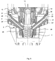
- ein vergrößerter Teilausschnitt aus dem Handextruderschweißgerät gemäß Figur 1 durch den Kühlkörper und das Getriebegehäuse;
- Figur 6
- die Rückseite des zweiteiligen Kühlkörpers;
- Figur 7
- eine andere Ausführungsform eines Handextruderschweißgeräts ohne Antriebseinheit und Gebläse umschließendes Gehäuse und
- Figur 8
- verschiedene perspektivische Ansichten des Klemmflansches für das Handextruderschweißgerät gemäß Figur 7 von vorne (Figur 8a) und von hinten (Figur 8b).
- Figur 1 zeigt im Längsschnitt ein Handextruderschweißgerät 1 mit einem Gehäuse 2, das vorzugsweise aus zwei seitlichen Schalen gebildet wird, in dem ein Antriebsmotor 6 mit Getriebe 4 sowie ein Gebläsemotor 7 mit Gebläse 8 integriert ist. Im Anschluss an das Gebläse 8 findet sich die Heizeinrichtung 9. Das Getriebe 4 weist ein Gehäuse 10 auf, in dessen Lagerflansch 11 axial eine Extruderschnecke 3 einsteckbar ist. Zur radialen Fixierung der Extruderschnecke 3 in dem Lagerflansch 11 wird diese über einen zweiteiligen Kühlkörper 5, der gleichzeitig als Klemmflansch wirkt, zusammengezogen.
- Figur 2 zeigt in einer vergrößerten Ansicht das Gehäuse 10 aus einem Kokillenguss, das in dem erweiterten Bereich 10' die einzelnen Getriebeteile aufnimmt und am anderen Ende den Lagerflansch 11 zur Aufnahme der Extruderschnecke 3 aufweist. In dem Lagerflansch 11 befindet sich die Abgangswelle 12, die von dem stirnseitigen Ende in die Bohrung 13 in den Lagerflansch 11 bis zum Anschlag 14 eingeschoben wird. Vor dem Übergang in den erweiterten Bereich 10' befindet sich an dem Lagerflansch 11 eine Ringnut 20 für den Eingriff eines Klemmflansches, beispielsweise in Form des Kühlkörpers 5. Der Klemmflansch besteht aus mindestens zwei Hälften und sorgt durch das Verspannen der beiden Hälften für eine entsprechende Klemmung des Lagerflansches 11. Durch den Hinterschnitt am Lagerflansch 11 leitet der Klemmflansch die Kraft in das Axiallager 17 auf der Schneckenseite zurück. Am anderen Ende des Lagerflansches 11 ist ein Getriebeabgangszahnrad 15 aufgepresst, so dass die Abgangswelle 12 axial fixiert ist.
- Die Abgangswelle 12 ist in dem Lagerflansch 11 auf der Getriebeseite über ein in das Gehäuse 10 eingepresstes Rillenkugellager 16 und auf der Schneckenseite über ein in das Gehäuse 10 eingepresstes Nadel Radial-Axiallager 17 gelagert.
- Aus Figur 3 ist die Ausbildung der Bohrung 18 in der Abgangswelle 12 ersichtlich. Diese weist wie der Schaft 19 der Extruderschnecke 3 einen polygonförmigen Querschnitt auf, um das Drehmoment optimal zu übertragen und gleichzeitig eine einfache Justierung der Extruderschnecke 3 in der Abgangswelle 12 zu realisieren. Mit diesem Aufbau ist ein nominales Abgangsdrehmoment von 13 Nm und ein maximal Abgangsdrehmoment von ca. 20 Nm möglich.
- Figur 4 zeigt den vollständigen Zusammenbau des Getriebegehäuses 10 mit Stiften 21 als Verdrehsicherung, die in das Gehäuse 10 eingepresst sind und in entsprechende Schlitze in dem Klemmflansch eingreifen.
- Wie bereits vorstehend erwähnt, kann das allgemein als Klemmflansch bezeichnete Teil, das auf den Lagerflansch 11 wirkt, verschiedenartig ausgebildet sein. Bei dem Ausführungsbeispiel gemäß Figur 1 übernimmt der Kühlkörper 5 gleichzeitig die Funktion des Klemmflansches. In dem Kühlkörper 5 sind zusätzlich Einzugskanäle 24, 24' vorgesehen, die in den Einzugsbereich der Extruderschnecke 3 münden. Die Einzugskanäle 24, 24' weisen unterschiedliche Durchmesser auf, um unterschiedlich dicke Schweißdrähte einführen zu können. In dem Kühlkörper 5, der aus zwei Kühlkörperhälften 5' und 5" besteht, sind entsprechende halbrunde Stege 27 angeordnet, die an ihrem Ende in die Nut 20 eingreifen und an dem Lagerflansch 11 anliegen. Durch Verspannen der Kühlkörperhälften 5' und 5" mittels geeigneter Schraubverbindungen wird die entsprechende Anpresskraft erzeugt. Die Innenseite der beiden Kühlkörperhälften 5' und 5" sind in der Figur 6 dargestellt. Die Querschlitze 28 dienen dem Eingriff der Stifte 21, um eine zusätzliche Verdrehsicherung bereitzustellen. Die Öffnungen 22 dienen der Aufnahme von Schraubverbindungen.
- Figur 7 zeigt eine andere Ausführungsform eines Extruderschweißgerätes 1', bei dem das Getriebegehäuse 10 direkt an das eine Antriebseinrichtung umgebende Gehäuse 29 angeflanscht ist. Entsprechend ist nur ein ringförmiger Klemmflansch 50, der ebenfalls aus zwei Hälften besteht, vorgesehen.
- Der Klemmflansch 50 mit den beiden Klemmflanschhälften 50' und 50" ist in der Figur 8a von vorne dargestellt und zeigt die bereits im Zusammenhang mit dem Kühlkörper 5 beschriebenen Elemente, die gleich beziffert sind. Der Steg 27' greift am Ende in die Nut 20 am Lagerflansch 11 ein. Die Eintrittsöffnung 25 des jeweiligen Einzugskanals 24', 24" befindet sich seitlich und die Austrittsöffnung 26 an der jeweiligen Stirnseite des Klemmflansches 50' bzw. 50" (bzw. 5' und 5" in Figur 5). Figur 8b zeigt die Rückseite des Klemmflansches 50.
Claims (8)
- Handextruderschweißgerät (1) zum Verschweißen von thermoplastischen Kunststoffmaterialien mit einer Extruderschnecke (3) mit einem Befestigungsschaft (19) und einer Einrichtung zum axialen Befestigen der Extruderschnecke (3) mit dem Befestigungsschaft (19) an einer Antriebseinrichtung (6) mit einem Getriebe (4) gekennzeichnet durch, ein einstückiges Getriebegehäuse (10) mit einem topfförmigen Bereich (10') zur Aufnahme des Getriebes (4) und mit einem stirnseitigen Lagerflansch (11) zur Aufnahme der Extruderschnecke (3).
- Handextruderschweißgerät nach Anspruch 1, dadurch gekennzeichnet, dass in dem Lagerflansch (11) eine Abgangswelle (12) angeordnet ist, auf der am topfseitigen Ende ein Getriebeabgangszahnrad (15) befestigt ist und die eine Einstecköffnung (18) für den Befestigungsschaft (19) der Extruderschnecke (3) aufweist.
- Handextruderschweißgerät nach Anspruch 1 oder 2, gekennzeichnet durch mindestens einen zweiteiligen ringförmigen Klemmflansch (5, 50), der zum Klemmen des Lagerflansches (11)von außen auf den Lagerflansch (11) aufsetzbar ist.
- Handextruderschweißgerät nach Anspruch 3, dadurch gekennzeichnet, dass in dem Klemmflansch (5, 50) mindestens ein Einzugskanal (24,) für einen Schweißdraht angeordnet ist.
- Handextruderschweißgerät nach Anspruch 4, dadurch gekennzeichnet, dass der Einzugskanal (24) eine seitliche Eintrittsöffnung (25) und eine stirnseitige Austrittsöffnung (26) an dem Klemmflansch (5, 50) aufweist.
- Handextruderschweißgerät nach einem der vorangegangenen Ansprüche, dadurch gekennzeichnet, dass der Lagerflansch (11) einen ringförmigen Einschnitt (20) zur axialen Fixierung des Klemmflansches (5, 50) aufweist.
- Handextruderschweißgerät nach Anspruch 6, dadurch gekennzeichnet, dass die Klemmflanschhälften mittels Schraubverbindungen (22) zusammengezogen werden.
- Handextruderschweißgerät nach Anspruch 6 oder 7, dadurch gekennzeichnet, dass an dem Gehäuse (10) Verdrehsicherungen (21) für die Klemmflanschhälften (5', 5"; 50', 50") angeordnet sind.
Priority Applications (3)
| Application Number | Priority Date | Filing Date | Title |
|---|---|---|---|
| EP04021265.6A EP1634689B1 (de) | 2004-09-08 | 2004-09-08 | Handextruderschweissgerät |
| US11/219,011 US7416399B2 (en) | 2004-09-08 | 2005-09-02 | Handheld extruder welding device |
| CNB2005101037254A CN100564005C (zh) | 2004-09-08 | 2005-09-07 | 手持式挤压焊机 |
Applications Claiming Priority (1)
| Application Number | Priority Date | Filing Date | Title |
|---|---|---|---|
| EP04021265.6A EP1634689B1 (de) | 2004-09-08 | 2004-09-08 | Handextruderschweissgerät |
Publications (2)
| Publication Number | Publication Date |
|---|---|
| EP1634689A1 true EP1634689A1 (de) | 2006-03-15 |
| EP1634689B1 EP1634689B1 (de) | 2013-05-22 |
Family
ID=34926449
Family Applications (1)
| Application Number | Title | Priority Date | Filing Date |
|---|---|---|---|
| EP04021265.6A Expired - Lifetime EP1634689B1 (de) | 2004-09-08 | 2004-09-08 | Handextruderschweissgerät |
Country Status (3)
| Country | Link |
|---|---|
| US (1) | US7416399B2 (de) |
| EP (1) | EP1634689B1 (de) |
| CN (1) | CN100564005C (de) |
Cited By (4)
| Publication number | Priority date | Publication date | Assignee | Title |
|---|---|---|---|---|
| DE202007007282U1 (de) * | 2007-05-22 | 2008-10-02 | Leister Process Technologies | Extruderschweißeinrichtung |
| WO2010079140A1 (de) * | 2009-01-10 | 2010-07-15 | Dohle Extrusionstechnik Gmbh | Handschweissextruder mit haltegriff für die einhandbedienung |
| DE202010007466U1 (de) | 2010-06-01 | 2011-09-28 | Wegener International Gmbh | Handschweißgerät |
| CN105618343A (zh) * | 2016-01-21 | 2016-06-01 | 河北建筑工程学院 | 手动挤胶装置 |
Families Citing this family (10)
| Publication number | Priority date | Publication date | Assignee | Title |
|---|---|---|---|---|
| US8133345B2 (en) * | 2007-04-05 | 2012-03-13 | Curtis Goad | Method and apparatus for lining process tanks |
| US10138053B2 (en) | 2007-04-05 | 2018-11-27 | Curtis Goad | Methods and apparatus for lining process tanks |
| US9278478B2 (en) | 2007-04-05 | 2016-03-08 | Curtis Goad | Methods and apparatus for lining process tanks |
| US9759380B2 (en) | 2012-03-22 | 2017-09-12 | Curtis Goad | Liners and linings for tanks and other liquid containment vessels |
| US8955711B2 (en) | 2012-03-22 | 2015-02-17 | Curtis Goad | Liners and linings for tanks |
| US10392186B2 (en) | 2012-03-22 | 2019-08-27 | Curtis Goad | Liners and linings for tanks and other liquid containment vessels |
| CN107472723B (zh) * | 2017-08-03 | 2024-07-02 | 上海鸿研物流技术有限公司 | 流体排放系统及其挤推器 |
| US11376783B2 (en) | 2018-10-31 | 2022-07-05 | Curtis Goad | Corner profiles and/or corner reinforcement for liners and linings suitable for use with tanks and other storage/containment vessels |
| JP7706374B2 (ja) * | 2019-02-25 | 2025-07-11 | スリーエム イノベイティブ プロパティズ カンパニー | フィラメント接着剤ディスペンサ |
| US11396125B2 (en) | 2019-04-19 | 2022-07-26 | Goad Company | Liners and methods of making liners |
Citations (6)
| Publication number | Priority date | Publication date | Assignee | Title |
|---|---|---|---|---|
| US3750905A (en) * | 1972-08-23 | 1973-08-07 | Hardman Inc | Hand-held extruding apparatus |
| US3953006A (en) * | 1974-02-04 | 1976-04-27 | Thiokol Corporation | Portable conversion and dispensing apparatus for curable elastomeric compounds |
| DE9010633U1 (de) * | 1989-08-24 | 1990-09-20 | Leidl, Hagen, 7062 Rudersberg | Hilfseinrichtung für eine Hand-Werkzeugmaschine |
| EP0594889A1 (de) * | 1992-10-30 | 1994-05-04 | Munsch Chemie-Pumpen GmbH | Schweissgerät |
| EP0887116A2 (de) * | 1997-06-25 | 1998-12-30 | Peter Christian Dohle | Schweissextruder |
| DE19952166A1 (de) * | 1999-10-29 | 2001-05-17 | Dohle Extrusionstechnik Gmbh | Schweißgerät für thermoplastische Kunststoffe |
Family Cites Families (5)
| Publication number | Priority date | Publication date | Assignee | Title |
|---|---|---|---|---|
| JPS608013A (ja) | 1983-06-28 | 1985-01-16 | Mitsubishi Heavy Ind Ltd | スクリユ混練機の移動調整装置 |
| US5005731A (en) * | 1989-06-08 | 1991-04-09 | Hardman Incorporated | Hand-held extruder |
| DE9311705U1 (de) * | 1993-08-05 | 1993-10-14 | Wegener Gmbh, 52074 Aachen | Kunststoffschweißgerät |
| DE59800028D1 (de) * | 1998-02-02 | 1999-10-14 | At Anlagetechnik Ag | Auslassvorrichtung zum dosierbaren Auslassen von Schüttgut aus einem Aufnahmebereich |
| DE29915768U1 (de) * | 1999-09-08 | 2000-10-19 | Wegener Gmbh, 52074 Aachen | Extruderschweißeinrichtung |
-
2004
- 2004-09-08 EP EP04021265.6A patent/EP1634689B1/de not_active Expired - Lifetime
-
2005
- 2005-09-02 US US11/219,011 patent/US7416399B2/en active Active
- 2005-09-07 CN CNB2005101037254A patent/CN100564005C/zh not_active Expired - Lifetime
Patent Citations (6)
| Publication number | Priority date | Publication date | Assignee | Title |
|---|---|---|---|---|
| US3750905A (en) * | 1972-08-23 | 1973-08-07 | Hardman Inc | Hand-held extruding apparatus |
| US3953006A (en) * | 1974-02-04 | 1976-04-27 | Thiokol Corporation | Portable conversion and dispensing apparatus for curable elastomeric compounds |
| DE9010633U1 (de) * | 1989-08-24 | 1990-09-20 | Leidl, Hagen, 7062 Rudersberg | Hilfseinrichtung für eine Hand-Werkzeugmaschine |
| EP0594889A1 (de) * | 1992-10-30 | 1994-05-04 | Munsch Chemie-Pumpen GmbH | Schweissgerät |
| EP0887116A2 (de) * | 1997-06-25 | 1998-12-30 | Peter Christian Dohle | Schweissextruder |
| DE19952166A1 (de) * | 1999-10-29 | 2001-05-17 | Dohle Extrusionstechnik Gmbh | Schweißgerät für thermoplastische Kunststoffe |
Cited By (5)
| Publication number | Priority date | Publication date | Assignee | Title |
|---|---|---|---|---|
| DE202007007282U1 (de) * | 2007-05-22 | 2008-10-02 | Leister Process Technologies | Extruderschweißeinrichtung |
| WO2010079140A1 (de) * | 2009-01-10 | 2010-07-15 | Dohle Extrusionstechnik Gmbh | Handschweissextruder mit haltegriff für die einhandbedienung |
| DE202010007466U1 (de) | 2010-06-01 | 2011-09-28 | Wegener International Gmbh | Handschweißgerät |
| EP2392445A2 (de) | 2010-06-01 | 2011-12-07 | Wegener International GmbH | Handschweißgerät |
| CN105618343A (zh) * | 2016-01-21 | 2016-06-01 | 河北建筑工程学院 | 手动挤胶装置 |
Also Published As
| Publication number | Publication date |
|---|---|
| US7416399B2 (en) | 2008-08-26 |
| US20060057241A1 (en) | 2006-03-16 |
| EP1634689B1 (de) | 2013-05-22 |
| CN1746008A (zh) | 2006-03-15 |
| CN100564005C (zh) | 2009-12-02 |
Similar Documents
| Publication | Publication Date | Title |
|---|---|---|
| EP1634689B1 (de) | Handextruderschweissgerät | |
| EP1637234B2 (de) | Handextruderschweissgerät | |
| EP2667819B1 (de) | Dentalbohrer und verfahren zu seiner herstellung | |
| DE60015636T2 (de) | Kompressionsknochenschraube und Hilfsinstrumente zu ihrer Befestigung | |
| DE19648868A1 (de) | Bohrwerkzeug mit hohlzylinderförmigem Trägerkörper | |
| EP0293706B1 (de) | Schrauber | |
| DE19861489B4 (de) | Verfahren und Vorrichtung zur Einspeisung von Kühl- und Schmiermittel in ein Werkzeug | |
| DE202014103665U1 (de) | Stator einer Exzenterschneckenpumpe zum Fördern einer fließfähigen Fördermasse, insbesondere einer Baustoffmischung wie Mörtel | |
| DE202008009720U1 (de) | Vorrichtung zur Nachbearbeitung einer Aufnahmebohrung für Glühkerzen | |
| DE4409983B4 (de) | Rohranfasgerät | |
| EP1375993A1 (de) | Kupplungsmuffe für gewellt ausgebildete Rohre | |
| AT412526B (de) | Zahnärztliches hand- oder winkelstück | |
| EP2058067B1 (de) | Vorrichtung mit einem Antrieb und einem Entgratwerkzeug sowie Entgratwerkzeug | |
| DE19952166B4 (de) | Schweißgerät für thermoplastische Kunststoffe | |
| DE102022206040A1 (de) | Gebaute Rotorwelle eines Elektromotors | |
| EP2392445A2 (de) | Handschweißgerät | |
| EP2995274B1 (de) | Zahnärztliches Handinstrument und Kopfgehäuse hierfür | |
| CH658802A5 (en) | Agitator mill | |
| EP1262303A1 (de) | Arbeitsorgan für eine Misch-und/oder Knet- und/oder Fördereinrichtung | |
| DE102016104477A1 (de) | Brauseschlauch | |
| EP2387966A1 (de) | Medizinisches, insbesondere zahnärztliches, Handstück | |
| EP0875327B1 (de) | Schneidkopf | |
| DE9002048U1 (de) | Beheizte Düse, sogenannte Langdüse für ein Kunststoff-Spritzgießwerkzeug | |
| DE102008012491A1 (de) | Oszillatorisch betriebene Säge-bzw. Fräsvorrichtung zum Fräsen halbkreisförmiger Nuten | |
| DE2107526A1 (de) | Zahnärztliches Ultraschallgerät |
Legal Events
| Date | Code | Title | Description |
|---|---|---|---|
| PUAI | Public reference made under article 153(3) epc to a published international application that has entered the european phase |
Free format text: ORIGINAL CODE: 0009012 |
|
| 17P | Request for examination filed |
Effective date: 20050531 |
|
| AK | Designated contracting states |
Kind code of ref document: A1 Designated state(s): AT BE BG CH CY CZ DE DK EE ES FI FR GB GR HU IE IT LI LU MC NL PL PT RO SE SI SK TR |
|
| AX | Request for extension of the european patent |
Extension state: AL HR LT LV MK |
|
| AKX | Designation fees paid |
Designated state(s): AT BE CH DE ES FI FR GB IT LI NL SE |
|
| REG | Reference to a national code |
Ref country code: HK Ref legal event code: DE Ref document number: 1090000 Country of ref document: HK |
|
| RAP1 | Party data changed (applicant data changed or rights of an application transferred) |
Owner name: LEISTER PROCESS TECHNOLOGIES |
|
| 17Q | First examination report despatched |
Effective date: 20080820 |
|
| RAP1 | Party data changed (applicant data changed or rights of an application transferred) |
Owner name: LEISTER TECHNOLOGIES AG |
|
| REG | Reference to a national code |
Ref country code: DE Ref legal event code: R079 Ref document number: 502004014184 Country of ref document: DE Free format text: PREVIOUS MAIN CLASS: B29C0047100000 Ipc: B29C0047380000 |
|
| GRAP | Despatch of communication of intention to grant a patent |
Free format text: ORIGINAL CODE: EPIDOSNIGR1 |
|
| RIC1 | Information provided on ipc code assigned before grant |
Ipc: B29C 47/38 20060101AFI20121019BHEP Ipc: B05C 17/005 20060101ALI20121019BHEP |
|
| GRAS | Grant fee paid |
Free format text: ORIGINAL CODE: EPIDOSNIGR3 |
|
| REG | Reference to a national code |
Ref country code: HK Ref legal event code: WD Ref document number: 1090000 Country of ref document: HK |
|
| GRAA | (expected) grant |
Free format text: ORIGINAL CODE: 0009210 |
|
| AK | Designated contracting states |
Kind code of ref document: B1 Designated state(s): AT BE CH DE ES FI FR GB IT LI NL SE |
|
| REG | Reference to a national code |
Ref country code: GB Ref legal event code: FG4D Free format text: NOT ENGLISH |
|
| REG | Reference to a national code |
Ref country code: CH Ref legal event code: EP |
|
| REG | Reference to a national code |
Ref country code: AT Ref legal event code: REF Ref document number: 612971 Country of ref document: AT Kind code of ref document: T Effective date: 20130615 |
|
| REG | Reference to a national code |
Ref country code: DE Ref legal event code: R096 Ref document number: 502004014184 Country of ref document: DE Effective date: 20130718 |
|
| REG | Reference to a national code |
Ref country code: CH Ref legal event code: NV Representative=s name: ABACUS PATENTANWAELTE KLOCKE SPAETH BARTH, CH |
|
| PG25 | Lapsed in a contracting state [announced via postgrant information from national office to epo] |
Ref country code: ES Free format text: LAPSE BECAUSE OF FAILURE TO SUBMIT A TRANSLATION OF THE DESCRIPTION OR TO PAY THE FEE WITHIN THE PRESCRIBED TIME-LIMIT Effective date: 20130902 Ref country code: FI Free format text: LAPSE BECAUSE OF FAILURE TO SUBMIT A TRANSLATION OF THE DESCRIPTION OR TO PAY THE FEE WITHIN THE PRESCRIBED TIME-LIMIT Effective date: 20130522 Ref country code: SE Free format text: LAPSE BECAUSE OF FAILURE TO SUBMIT A TRANSLATION OF THE DESCRIPTION OR TO PAY THE FEE WITHIN THE PRESCRIBED TIME-LIMIT Effective date: 20130522 |
|
| REG | Reference to a national code |
Ref country code: NL Ref legal event code: VDEP Effective date: 20130522 |
|
| PG25 | Lapsed in a contracting state [announced via postgrant information from national office to epo] |
Ref country code: NL Free format text: LAPSE BECAUSE OF FAILURE TO SUBMIT A TRANSLATION OF THE DESCRIPTION OR TO PAY THE FEE WITHIN THE PRESCRIBED TIME-LIMIT Effective date: 20130522 Ref country code: IT Free format text: LAPSE BECAUSE OF FAILURE TO SUBMIT A TRANSLATION OF THE DESCRIPTION OR TO PAY THE FEE WITHIN THE PRESCRIBED TIME-LIMIT Effective date: 20130522 |
|
| PLBE | No opposition filed within time limit |
Free format text: ORIGINAL CODE: 0009261 |
|
| STAA | Information on the status of an ep patent application or granted ep patent |
Free format text: STATUS: NO OPPOSITION FILED WITHIN TIME LIMIT |
|
| BERE | Be: lapsed |
Owner name: LEISTER TECHNOLOGIES A.G. Effective date: 20130930 |
|
| 26N | No opposition filed |
Effective date: 20140225 |
|
| GBPC | Gb: european patent ceased through non-payment of renewal fee |
Effective date: 20130908 |
|
| REG | Reference to a national code |
Ref country code: DE Ref legal event code: R097 Ref document number: 502004014184 Country of ref document: DE Effective date: 20140225 |
|
| REG | Reference to a national code |
Ref country code: FR Ref legal event code: ST Effective date: 20140530 |
|
| PG25 | Lapsed in a contracting state [announced via postgrant information from national office to epo] |
Ref country code: GB Free format text: LAPSE BECAUSE OF NON-PAYMENT OF DUE FEES Effective date: 20130908 Ref country code: BE Free format text: LAPSE BECAUSE OF NON-PAYMENT OF DUE FEES Effective date: 20130930 |
|
| PG25 | Lapsed in a contracting state [announced via postgrant information from national office to epo] |
Ref country code: FR Free format text: LAPSE BECAUSE OF NON-PAYMENT OF DUE FEES Effective date: 20130930 |
|
| REG | Reference to a national code |
Ref country code: AT Ref legal event code: MM01 Ref document number: 612971 Country of ref document: AT Kind code of ref document: T Effective date: 20130908 |
|
| PG25 | Lapsed in a contracting state [announced via postgrant information from national office to epo] |
Ref country code: AT Free format text: LAPSE BECAUSE OF NON-PAYMENT OF DUE FEES Effective date: 20130908 |
|
| REG | Reference to a national code |
Ref country code: DE Ref legal event code: R079 Ref document number: 502004014184 Country of ref document: DE Free format text: PREVIOUS MAIN CLASS: B29C0047380000 Ipc: B29C0048395000 |
|
| REG | Reference to a national code |
Ref country code: DE Ref legal event code: R082 Ref document number: 502004014184 Country of ref document: DE Representative=s name: WITTE, WELLER & PARTNER PATENTANWAELTE MBB, DE |
|
| P01 | Opt-out of the competence of the unified patent court (upc) registered |
Effective date: 20230502 |
|
| PGFP | Annual fee paid to national office [announced via postgrant information from national office to epo] |
Ref country code: DE Payment date: 20231027 Year of fee payment: 20 Ref country code: CH Payment date: 20231001 Year of fee payment: 20 |
|
| REG | Reference to a national code |
Ref country code: DE Ref legal event code: R071 Ref document number: 502004014184 Country of ref document: DE |
|
| REG | Reference to a national code |
Ref country code: CH Ref legal event code: PL |