EP1634997A1 - Streustoffverteiler für Streufahrzeuge - Google Patents
Streustoffverteiler für Streufahrzeuge Download PDFInfo
- Publication number
- EP1634997A1 EP1634997A1 EP04021841A EP04021841A EP1634997A1 EP 1634997 A1 EP1634997 A1 EP 1634997A1 EP 04021841 A EP04021841 A EP 04021841A EP 04021841 A EP04021841 A EP 04021841A EP 1634997 A1 EP1634997 A1 EP 1634997A1
- Authority
- EP
- European Patent Office
- Prior art keywords
- scattering
- wall
- chamber
- opening
- feed device
- Prior art date
- Legal status (The legal status is an assumption and is not a legal conclusion. Google has not performed a legal analysis and makes no representation as to the accuracy of the status listed.)
- Granted
Links
- 239000000463 material Substances 0.000 claims abstract description 24
- 239000000126 substance Substances 0.000 claims abstract description 22
- 150000003839 salts Chemical class 0.000 description 12
- 239000012267 brine Substances 0.000 description 9
- HPALAKNZSZLMCH-UHFFFAOYSA-M sodium;chloride;hydrate Chemical compound O.[Na+].[Cl-] HPALAKNZSZLMCH-UHFFFAOYSA-M 0.000 description 8
- 239000000203 mixture Substances 0.000 description 2
- 230000035515 penetration Effects 0.000 description 2
- 230000001419 dependent effect Effects 0.000 description 1
- 230000000694 effects Effects 0.000 description 1
Images


Classifications
-
- E—FIXED CONSTRUCTIONS
- E01—CONSTRUCTION OF ROADS, RAILWAYS, OR BRIDGES
- E01C—CONSTRUCTION OF, OR SURFACES FOR, ROADS, SPORTS GROUNDS, OR THE LIKE; MACHINES OR AUXILIARY TOOLS FOR CONSTRUCTION OR REPAIR
- E01C19/00—Machines, tools or auxiliary devices for preparing or distributing paving materials, for working the placed materials, or for forming, consolidating, or finishing the paving
- E01C19/12—Machines, tools or auxiliary devices for preparing or distributing paving materials, for working the placed materials, or for forming, consolidating, or finishing the paving for distributing granular or liquid materials
- E01C19/20—Apparatus for distributing, e.g. spreading, granular or pulverulent materials, e.g. sand, gravel, salt, dry binders
- E01C19/201—Apparatus for distributing, e.g. spreading, granular or pulverulent materials, e.g. sand, gravel, salt, dry binders with driven loosening, discharging or spreading parts, e.g. power-driven, drive derived from road-wheels
- E01C19/202—Apparatus for distributing, e.g. spreading, granular or pulverulent materials, e.g. sand, gravel, salt, dry binders with driven loosening, discharging or spreading parts, e.g. power-driven, drive derived from road-wheels solely rotating, e.g. discharging and spreading drums
- E01C19/203—Centrifugal spreaders with substantially vertical axis
Definitions
- the invention relates to a scattering distributor for scattering vehicles with a rotatable about an axis scattering element and a feeder for supplying a scattering material and a scattering vehicle with such a scattering distributor.
- the scattering agent distributors consist of a spreading plate, which is provided with guide elements.
- the scattering material for example salt or grit, is fed at a certain point to the rotating spreading plate.
- the scattering material is thrown by the rotation of the spreading plate to the outside.
- the salt In winter service, the salt is usually applied together with a brine to improve the effect of the salt.
- a brine to improve the effect of the salt.
- the mixture of salt and brine tends to blockages in the feeder.
- the two components are introduced separately and applied together to the spreading plate, there is no adequate mixing of salt and brine. The actual advantages of the salt-brine mixture are then not fully effective.
- the invention is therefore based on the object of specifying a scattering agent distributor for spreading vehicles, with which the spreading of the scattering material can be improved.
- the scattering substance distributor according to the invention for spreading vehicles has a scattering element rotatable about an axis and a feeding device for feeding at least one scattering substance. Furthermore, a chamber disposed about the axis is provided, wherein the scattering element adjoins radially outside the chamber and the chamber is delimited with an outer wall to the scattering element and has rotating driver elements and an opening in the outer wall and the feed device is arranged such that the Scattering material is first supplied to the chamber before passes through the opening in the outer wall of the scattering element.
- a scattering vehicle is provided with such a scattering distributor.
- the residence time can be significantly increased, so that, for example, in the task of salt and brine sufficient time exists for the salt to penetrate the salt.
- the outer wall of the chamber is cylindrical and fixed. Furthermore, the rotating driver elements divide the chamber into individual segments.
- the feed device is preferably arranged with respect to the opening in the outer wall such that the supplied scattering material is held over an angular range of at least 180 ° in the chamber.
- a particularly advantageous embodiment is that the outer wall about the axis rotatable and arrestable arranges, as a result, the scattering pattern can be adjusted specifically. In the experiments on which the invention is based, it has been shown that the spreading pattern is significantly sharper defined by the outer wall, whereby up to 20% of the scattering material can be saved.
- the chamber is surrounded by an inner wall arranged concentrically to the outer wall in an inner Divided portion and an outer portion, wherein the two portions are connected via an opening in the inner wall with each other.
- the feed device is then expediently arranged such that the scattering material is first supplied to the inner portion of the chamber, which then passes through the opening of the inner wall in the outer portion and through the opening in the outer wall of the scattering element. In this way, there is the possibility that the supplied grit is held over an angular range of at least 360 ° in the chamber. In the experiments on which the invention is based, it has been found that even with a separate introduction of salt and brine, a sufficient penetration and thorough mixing takes place in a simultaneous task.
- FIG. 9 shows a scattering vehicle 100 with a scattering agent distributor 101 attached to the rear end of the vehicle.
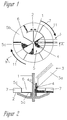
- the scattering material distributor consists essentially of a rotatable about an axis 1 scattering element 2 (rotational direction 11), a feeding device 3 for supplying at least one scattering material 4 and a arranged about the axis of the chamber 5, wherein the scattering element 2 connects radially outside the chamber and the chamber is delimited with an outer wall 5a to the scattering element.
- the chamber 5 also has rotating driver elements 6 and an opening 5b in the outer wall 5a.
- the scattering element 2 is provided with guide elements 7, which are arranged radially in the illustrated embodiment.
- the outer wall 5a is fixed during operation.
- the rotating driver elements 6 are arranged radially and extend from the axis 1 to the outer wall 5a, so that the chamber is divided into individual segments.
- the scattering element 2 rotate with its guide elements 7 and the driver elements 6 in the chamber about the axis 1.
- the feed device 3 is designed such that the first scattering substance 4 can be supplied via a first line 3a and a second scattering material 4a can be supplied via a second line 3b.
- the first scattering substance is salt and the second scattering substance 4a is a brine.
- the scattering device is arranged such that the or the scattering materials are first supplied to the chamber 5, wherein the task point radially inward, i. near the axis 1, is provided.
- the grit is then transported over the driver 6 about the axis 1, wherein it is pressed by the centrifugal force to the outer wall 5a.
- the scattering substance reaches the scattering element and is scattered by means of the guide elements 7.
- the feed device 3 is arranged opposite to the opening 5b, so that the grit is first transported over an angular range of at least 180 ° in the chamber. Due to the centrifugal forces acting there, there is the possibility that these penetrate especially when two stray substances are dispensed with. This has proven particularly effective with the addition of salt and brine.
- Fig. 4 shows a scattering pattern 8, which results in a certain orientation of the opening 5b with respect to the direction of travel 9 of the vehicle and the direction of rotation 11 of the scattering element.
- Fig. 5 shows a scattering pattern 8 ', which has resulted by adjusting the wall 5a.
- the outer wall 5a of the chamber thus enables a very simple positioning of the scattering pattern.
- the above-described spreading material distributor is also characterized by the fact that the lateral boundaries 8a, 8b and 8'a, 8'b of the scattering patterns 8 and 8 'are very clearly visible.
- the proportion of the scattering substance that is scattered beyond the desired ranges is relatively low in the above-described scattering agent distributor, so that compared to conventional scattering agent distributors, up to 20% of scattering material can be saved.
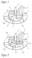
- FIGS. 6-8 a second embodiment of a scattering distributor for spreading vehicles will be described with reference to FIGS. 6-8. It will be the same reference numerals as used in the first embodiment for the same components.
- the difference from the first exemplary embodiment consists in particular in that the chamber 5 is subdivided into an inner partial area and an outer partial area by an inner wall 5d arranged concentrically to the outer wall 5a, the two partial areas being connected to each other via an opening 5e in the inner wall 5d Connection stand.
- Both the outer wall 5a and the inner wall 5d are stationary during operation, so that the transport of the scattering material by the rotating driver elements 6 takes place, the extend radially outward both over the inner and over the outer portion, as can be seen in particular from Fig. 7.
- the advantage of this further subdivision is, above all, that the residence time of the scattering substance or of the scattering substances can be further increased, since the scattering substances can remain in the chamber 5 over an angular range of at least 360 °.
- the driver elements 6 divide both the inner and the outer portion into individual segments.
- the feed device 3 is arranged so that the scattering substances are supplied in the region of a segment in the inner portion. Due to the centrifugal force, the scattering substances are pressed in the individual segments outwardly against the wall 5d and transported over an angular range ⁇ to the opening 5e, where they enter a segment-like section in the outer portion and over a wider angular range ⁇ to the opening 5b in the outer wall 5a are transported. There, the scattering substance reaches the rotating scattering element 7 and is scattered by the guide elements 7.
- the adjustment of the scattering pattern is in turn carried out by turning the outer wall 5a about the axis 1.
- the inner wall 5d can either be rotated and locked together with the outer wall 5a or separately from this. Within the scope of the invention, it would of course also be conceivable if the chamber is subdivided by corresponding walls in the further subregions.
- either a common or separate drives can be provided, which are conventionally adjustable in their speed.
- the scattering substance distributor according to the invention is characterized in particular by the supply of two different scattering substances, in particular salt and brine, by a thorough mixing and penetration of the two scattering substances.
- Another advantage of the spreader dispenser is the generation of a spicy delimited spread pattern and the easy way to adjust the scattered image. As a result, it is possible to deliberately apply the scattering material to the desired areas, whereby up to 20% of scattering material can be saved in comparison to conventional scattering substance distributors.
Landscapes
- Engineering & Computer Science (AREA)
- Architecture (AREA)
- Civil Engineering (AREA)
- Structural Engineering (AREA)
- Nozzles (AREA)
- Catching Or Destruction (AREA)
- Crushing And Pulverization Processes (AREA)
- Feeding, Discharge, Calcimining, Fusing, And Gas-Generation Devices (AREA)
- Braiding, Manufacturing Of Bobbin-Net Or Lace, And Manufacturing Of Nets By Knotting (AREA)
- Materials For Medical Uses (AREA)
Abstract
Description
- Die Erfindung betrifft einen Streustoffverteiler für Streufahrzeuge mit einem um eine Achse rotierbaren Streuelement und einer Zuführeinrichtung zum Zuführen eines Streustoffs sowie ein Streufahrzeug mit einem derartigen Streustoffverteiler.
- Üblicherweise bestehen die Streustoffverteiler aus einem Streuteller, der mit Leitelementen versehen ist. Der Streustoff, beispielsweise Salz oder Splitt, wird an einer bestimmten Stelle dem rotierenden Streuteller zugeführt. Der Streustoff wird durch die Rotation des Streutellers nach außen geschleudert. Durch Veränderung des Abwurfpunktes an dem der Streustoff dem Streuteller zugeführt wird, lässt sich Positionierung des Streubilds in begrenztem Maße einstellen.
- Im Winterdienst wird das Salz meist zusammen mit einer Sole ausgebracht, um die Wirkung des Salzes zu verbessern. Dabei ergibt sich jedoch das Problem, dass das Gemisch aus Salz und Sole zu Verstopfungen im Bereich der Zuführeinrichtung neigt. Werden hingegen die beiden Bestandteile getrennt herangeführt und gemeinsam auf den Streuteller aufgebracht, findet keine ausreichende Durchmischung von Salz und Sole statt. Die eigentlichen Vorteile des Salz-Sole-Gemisches kommen dann nicht voll zum Tragen.
- Die Erfindung liegt daher die Aufgabe zugrunde, einen Streustoffverteiler für Streufahrzeuge anzugeben, mit dem das Ausbringen des Streustoffs verbessert werden kann.
- Erfindungsgemäß wird diese Aufgabe durch die Merkmale der Ansprüche 1 bzw. 10 gelöst.
- Weitere Ausgestaltungen der Erfindung sind Gegenstand der Unteransprüche.
- Der erfindungsgemäße Streustoffverteiler für Streufahrzeuge weist ein um eine Achse rotierbares Streuelement und eine Zuführeinrichtung zum Zuführen wenigstens eines Streustoffs auf. Weiterhin ist eine um die Achse angeordnete Kammer vorgesehen, wobei sich das Streuelement radial außerhalb der Kammer anschließt und die Kammer mit einer äußeren Wandung zum Streuelement abgegrenzt ist und rotierende Mitnehmerelemente sowie eine Öffnung in der äußeren Wandung aufweist und die Zuführeinrichtung derart angeordnet ist, dass der Streustoff zunächst der Kammer zugeführt wird, bevor durch die Öffnung in der äußeren Wandung auf das Streuelement gelangt.
- Weiterhin ist ein Streufahrzeug mit einem derartigen Streustoffverteiler vorgesehen.
- In dem der Streustoff zunächst der Kammer zugeführt wird, kann die Verweilzeit deutlich erhöht werden, so dass beispielsweise bei der Aufgabe von Salz und Sole ausreichend Zeit besteht, damit die Sole das Salz durchdringt.
- Gemäß einem bevorzugten Ausgestaltung ist die äußere Wandung der Kammer zylindrisch und feststehend ausgebildet. Weiterhin unterteilen die rotierenden Mitnehmerelemente die Kammer in einzelne Segmente.
- Die Zuführeinrichtung wird vorzugsweise in Bezug auf die Öffnung in der äußeren Wandung derart angeordnet, dass der zugeführte Streustoff über einen Winkelbereich von wenigstens 180° in der Kammer gehalten wird. Eine besonders vorteilhafte Ausgestaltung besteht darin, dass man die äußere Wandung um die Achse verdreh-und arretierbar anordnet, da hierdurch das Streubild gezielt eingestellt werden kann. Bei den der Erfindung zugrundeliegenden Versuchen hat sich gezeigt, dass durch die äußere Wandung das Streubild wesentlich schärfer abgegrenzt wird, wodurch bis zu 20% des Streustoffs eingespart werden kann.
- Gemäß einer weiteren Ausgestaltung der Erfindung ist die Kammer durch eine konzentrisch zur äußeren Wandung angeordnete innere Wandung in einen inneren Teilbereich und einen äußeren Teilbereich unterteilt, wobei die beiden Teilbereich über eine Öffnung in der inneren Wandung miteinander in Verbindung stehen. Die Zuführeinrichtung wird dann zweckmäßigerweise derart angeordnet, dass der Streustoff zunächst dem inneren Teilbereich der Kammer zugeführt wird, der dann über die Öffnung der inneren Wandung in den äußeren Teilbereich und durch die Öffnung in den äußeren Wandung auf das Streuelement gelangt. Auf diese Weise besteht die Möglichkeit, dass das zugeführte Streugut über einen Winkelbereich von wenigstens 360° in der Kammer gehalten wird. Bei den der Erfindung zugrundeliegenden Versuchen hat sich gezeigt, dass selbst bei einem separaten Heranführen Salz und Sole bei einer gleichzeitigen Aufgabe eine ausreichende Durchdringung und Durchmischung stattfindet.
- Weitere Ausgestaltungen und Vorteile der Erfindung werden im folgenden anhand der Beschreibung zweier Ausführungsbeispiele und der Zeichnung näher erläutert.
- In der Zeichnung zeigen
- Fig. 1
- eine schematische Draufsicht des Streustoffverteilers gemäß einem ersten Ausführungsbeispiel,
- Fig. 2
- eine Schnittdarstellung längs der Linie A-A der Fig. 1,
- Fig. 3
- eine dreidimensionale Darstellung des Streustoffverteilers gemäß Fig. 1,
- Fig. 4
- eine Darstellung des Streustoffverteilers gemäß Fig. 1 mit einem ersten Streubild,
- Fig. 5
- eine Darstellung des Streustoffverteilers gemäß Fig. 1 mit einem zweiten Streubild,
- Fig. 6
- eine schematische Draufsicht des Streustoffverteilers gemäß einem zweiten Ausführungsbeispiel,
- Fig. 7
- eine Schnittdarstellung längs der Linie B-B der Fig. 6 und
- Fig. 8
- eine dreidimensionale Darstellung des Streustoffverteilers gemäß Fig. 6.
- Fig. 9
- eine schematische Seiten- und Hinteransicht eines Streufahrzeuges.
- In Fig. 9 ist ein Streufahrzeug 100 mit einem am hinteren Ende des Fahrzeugs angebrachten Streustoffverteiler 101.
- Anhand der Fig. 1 bis 4 wird zunächst ein erstes Ausführungsbeispiel dieses Streustoffverteilers für Streufahrzeuge näher erläutert. Der Streustoffverteiler besteht im wesentlichen aus einem um eine Achse 1 rotierbaren Streuelement 2 (Drehrichtung 11), einer Zuführeinrichtung 3 zum Zuführen wenigstens eines Streustoffs 4 sowie einer um die Achse angeordnete Kammer 5, wobei sich das Streuelement 2 radial außerhalb der Kammer anschließt und die Kammer mit einer äußeren Wandung 5a zum Streuelement abgrenzt ist. Die Kammer 5 weist ferner rotierende Mitnehmerelemente 6 sowie eine Öffnung 5b in der äußeren Wandung 5a auf.
- Das Streuelement 2 ist mit Leitelementen 7 versehen, die im dargestellten Ausführungsbeispiel radial angeordnet sind.
- Die äußere Wandung 5a ist während des Betriebes feststehend ausgebildet. Die rotierenden Mitnehmerelemente 6 sind radial angeordnet und erstrecken sich von der Achse 1 bis zur äußeren Wandung 5a, so dass die Kammer in einzelne Segmente unterteilt wird.
- Im dargestellten Ausführungsbeispiel sind neben der äußeren Wandung 5a auch der Boden 5c der Kammer 5 während des Betriebes feststehend ausgebildet, während sich das Streuelement 2 mit seinen Leitelementen 7 und die Mitnehmerelemente 6 in der Kammer um die Achse 1 rotieren.
- Im Rahmen der Erfindung ist es selbstverständlich auch möglich, dass lediglich die Wandung 5b feststehend ausgebildet ist, während der Boden 5c mitrotiert. In diesem Fall würde man zweckmäßigerweise den Boden 5c und das Streuelement als eine durchgehende Scheibe ausbilden. Es wäre aber auch denkbar, dass man das Streuelement als Scheibe ausbildet, die unmittelbar unterhalb der Kammer 5 angeordnet ist und im Durchmesser entsprechend größer ausgebildet ist, so dass sich eine ähnliche Draufsicht wie in Fig. 1 ergibt.
- Im dargestellten Ausführungsbeispiel ist die Zuführeinrichtung 3 so ausgebildet, dass über eine erste Leitung 3a der erste Streustoff 4 und über eine zweite Leitung 3b ein zweiter Streustoff 4a zugeführt werden können. Bei dem ersten Streustoff handelt es sich zum Beispiel um Salz und beim zweiten Streustoff 4a um eine Sole.
- Wie insbesondere aus Fig. 1 ersichtlich wird, ist die Streueinrichtung derart angeordnet, dass der bzw. die Streustoffe zunächst der Kammer 5 zugeführt werden, wobei die Aufgabenstelle radial innen, d.h. in der Nähe der Achse 1, vorgesehen ist. Das Streugut wird dann über die Mitnehmer 6 um die Achse 1 transportiert, wobei es durch die Fliehkraft an die äußere Wandung 5a gedrückt wird. Sobald die Öffnung 5b erreicht ist, gelangt der Streustoff auf das Streuelement und wird mittels der Leitelemente 7 verstreut.
- Die Zuführeinrichtung 3 ist gegenüber der Öffnung 5b derart angeordnet, so dass das Streugut zunächst über einen Winkelbereich von wenigstens 180° in der Kammer transportiert wird. Durch die dort wirkenden Fliehkräfte besteht insbesondere bei Aufgabe von zwei Streustoffen die Möglichkeit, dass sich diese durchdringen. Dies hat sich insbesondere bei Zugabe von Salz und Sole als besonders wirkungsvoll erwiesen.
- Fig. 4 zeigt ein Streubild 8, welches sich bei einer bestimmten Ausrichtung der Öffnung 5b im Bezug auf die Fahrtrichtung 9 des Fahrzeuges und die Drehrichtung 11 des Streuelements ergibt. Durch Verdrehen der Wandung 5a in Richtung des Doppelpfeils 10 kann das Streubild gezielt an die jeweilige Situation angepasst werden.
- Fig. 5 zeigt ein Streubild 8', welches sich durch Verstellung der Wandung 5a ergeben hat.
- Die äußere Wandung 5a der Kammer ermöglicht somit eine sehr einfache Positionierung des Streubildes. Der obenbeschriebene Streustoffverteiler zeichnet sich darüber hinaus dadurch aus, dass sich die seitlichen Grenzen 8a, 8b bzw. 8'a, 8'b der Streubilder 8 bzw. 8' sehr deutlich abzeichnen. Der Anteil des Streustoffs, der über die gewünschten Bereiche hinaus verstreut wird, ist bei dem obenbeschriebenen Streustoffverteiler relativ gering, so dass gegenüber herkömmlichen Streustoffverteiler bis zu 20% Streustoff eingespart werden kann.
- Im folgenden wird anhand der Fig. 6-8 ein zweites Ausführungsbeispiel eines Streustoffverteilers für Streufahrzeuge beschrieben. Es werden dabei für gleiche Bauteile die selben Bezugszeichen wie im ersten Ausführungsbeispiel verwendet.
- Der Unterschied zum ersten Ausführungsbeispiel besteht insbesondere darin, dass die Kammer 5 durch eine konzentrisch zur äußeren Wandung 5a angeordnete innere Wandung 5d in einen inneren Teilbereich und einen äußeren Teilbereich unterteilt ist, wobei die beiden Teilbereiche über eine Öffnung 5e in der inneren Wandung 5d miteinander in Verbindung stehen. Sowohl die äußere Wandung 5a als auch die innere Wandung 5d sind während des Betriebes feststehend angeordnet, so dass der Transport des Streustoffs durch die rotierenden Mitnehmerelemente 6 erfolgt, die sich radial nach außen sowohl über den inneren als auch über den äußeren Teilbereich erstrecken, wie insbesondere aus Fig. 7 ersichtlich wird.
- Der Vorteil dieser weiteren Unterteilung besteht vor allem darin, dass die Verweilzeit des Streustoffs bzw. der Streustoffe weiter erhöht werden kann, da die Streustoffe über einen Winkelbereich von wenigstens 360° in der Kammer 5 verbleiben können.
- Die Mitnehmerelemente 6 unterteilen sowohl den inneren als auch den äußeren Teilbereich in einzelne Segmente. Die Zuführeinrichtung 3 ist so angeordnet, dass die Streustoffe im Bereich eines Segments im inneren Teilbereich zugeführt werden. Aufgrund der Fliehkraft werden die Streustoffe in den einzelnen Segmenten nach außen gegen die Wandung 5d gedrückt und über einen Winkelbereich α bis zur Öffnung 5e weitertransportiert, wo sie in einen segmentartigen Abschnitt im äußeren Teilbereich gelangen und über einen weiteren Winkelbereich β bis zur Öffnung 5b in der äußeren Wandung 5a transportiert werden. Dort erreicht der Streustoff das rotierende Streuelement 7 und wird durch die Leitelemente 7 verstreut. Die Einstellung des Streubildes erfolgt wiederum durch Verdrehen der äußeren Wandung 5a um die Achse 1. Die innere Wandung 5d kann dabei entweder zusammen mit der äußeren Wandung 5a oder separat von dieser verdreht und arretiert werden. Im Rahmen der Erfindung wäre es selbstverständlich auch denkbar, wenn man die Kammer durch entsprechende Wandungen im weitere Teilbereiche unterteilt.
- Für das Streuelement 2 und die Mitnehmerelemente 6 kann entweder ein gemeinsamer oder separate Antriebe vorgesehen werden, die in herkömmlicherweise in ihrer Geschwindigkeit regelbar sind.
- Der erfindungsgemäße Streustoffverteiler zeichnet sich insbesondere bei der Zuführung von zwei unterschiedlichen Streustoffen, insbesondere Salz und Sole, durch eine gute Durchmischung und Durchdringung der beiden Streustoffe aus. Ein weiterer Vorteil des Streustoffverteilers besteht in der Erzeugung eines scharf abgegrenzten Streubildes und der einfachen Möglichkeit zur Verstellung des Streubildes aus. Dadurch ist es möglich, dass den Streustoff gezielt auf die gewünschten Bereiche auszubringen, wodurch gegenüber herkömmlichen Streustoffverteilern bis 20% Streustoff eingespart werden kann.
Claims (10)
- Streustoffverteiler für Streufahrzeuge mit einem um eine Achse (1) rotierbaren Streuelement (2) und einer Zuführeinrichtung (3) zum Zuführen wenigstens eines Streustoffs (4),
dadurch gekennzeichnet, dass eine um die Achse angeordnete Kammer (5) vorgesehen ist und sich das Streuelement radial außerhalb der Kammer anschließt, wobei die Kammer mit einer äußeren Wandung (5a) zum Streuelement abgegrenzt ist und rotierende Mitnehmerelemente sowie eine Öffnung (5b) in der äußeren Wandung aufweist und die Zuführeinrichtung derart angeordnet ist, dass der Streustoff zunächst der Kammer zugeführt wird, bevor er über die Öffnung (5b) in der äußeren Wandung (5a) auf das Streuelement gelangt. - Streustoffverteiler nach Anspruch 1, dadurch gekennzeichnet, dass die äußere Wandung (5a) der Kammer zylindrisch und feststehend ausgebildet ist.
- Streustoffverteiler nach Anspruch 1, dadurch gekennzeichnet, dass die Kammer durch eine konzentrisch zur äußeren Wandung angeordnete innere Wandung in einen inneren Teilbereich und einen äußeren Teilbereich unterteilt ist, wobei die beiden Teilbereiche über eine Öffnung in der inneren Wandung miteinander in Verbindung stehen.
- Streustoffverteiler nach Anspruch 3, dadurch gekennzeichnet, dass die Zuführeinrichtung (3) derart angeordnet ist, dass der Streustoff (4) zunächst dem inneren Teilbereich der Kammer (5) zugeführt wird, dann über die Öffnung (5e) der inneren Wandung (5d) in den äußeren Teilbereich und durch die Öffnung (5b) in der äußeren Wandung (5a) auf das Streuelement gelangt.
- Streustoffverteiler nach Anspruch 1, dadurch gekennzeichnet, dass die äußere Wandung (5a) zur Einstellung des Streubildes (8, 8')um die Achse (1) verdreh-und arretierbar ist.
- Streustoffverteiler nach Anspruch 3, dadurch gekennzeichnet, dass die innere Wandung um die Achse verdreh- und arretierbar ist.
- Streustoffverteiler nach Anspruch 1, dadurch gekennzeichnet, dass die Zuführeinrichtung (3) zur separaten Zuführung von wenigstens zwei unterschiedlichen Streustoffen (4, 4a) ausgebildet ist.
- Streustoffverteiler nach Anspruch 1, dadurch gekennzeichnet, dass die Zuführeinrichtung (3) in Bezug auf die Öffnung (5b) in der äußeren Wandung (5a) derart angeordnet ist, dass der zugeführte Streustoff über einen Winkelbereich von wenigstens 180° in der Kammer gehalten wird.
- Streustoffverteiler nach Anspruch 3, dadurch gekennzeichnet, dass die Öffnungen (5b) in der äußeren bzw. inneren Wandung (5a, 5d) und die Zuführeinrichtung (3) derart angeordnet sind, dass der zugeführte Streustoff über einen Winkelbereich von wenigstens 360° in der Kammer gehalten wird.
- Streufahrzeug mit einem Streustoffverteiler 101 nach einem oder mehreren der vorangegangenen Ansprüche.
Priority Applications (4)
| Application Number | Priority Date | Filing Date | Title |
|---|---|---|---|
| EP04021841A EP1634997B1 (de) | 2004-09-14 | 2004-09-14 | Streustoffverteiler für Streufahrzeuge |
| DK04021841T DK1634997T3 (da) | 2004-09-14 | 2004-09-14 | Strömaterialefordeler for strököretöjer |
| DE502004006199T DE502004006199D1 (de) | 2004-09-14 | 2004-09-14 | Streustoffverteiler für Streufahrzeuge |
| AT04021841T ATE386169T1 (de) | 2004-09-14 | 2004-09-14 | Streustoffverteiler für streufahrzeuge |
Applications Claiming Priority (1)
| Application Number | Priority Date | Filing Date | Title |
|---|---|---|---|
| EP04021841A EP1634997B1 (de) | 2004-09-14 | 2004-09-14 | Streustoffverteiler für Streufahrzeuge |
Publications (2)
| Publication Number | Publication Date |
|---|---|
| EP1634997A1 true EP1634997A1 (de) | 2006-03-15 |
| EP1634997B1 EP1634997B1 (de) | 2008-02-13 |
Family
ID=34926535
Family Applications (1)
| Application Number | Title | Priority Date | Filing Date |
|---|---|---|---|
| EP04021841A Expired - Lifetime EP1634997B1 (de) | 2004-09-14 | 2004-09-14 | Streustoffverteiler für Streufahrzeuge |
Country Status (4)
| Country | Link |
|---|---|
| EP (1) | EP1634997B1 (de) |
| AT (1) | ATE386169T1 (de) |
| DE (1) | DE502004006199D1 (de) |
| DK (1) | DK1634997T3 (de) |
Cited By (2)
| Publication number | Priority date | Publication date | Assignee | Title |
|---|---|---|---|---|
| EP1942230A1 (de) * | 2006-12-29 | 2008-07-09 | Giletta S.p.A. | Streustoffverteiler für Streufahrzeuge |
| EP2826919A1 (de) * | 2013-07-16 | 2015-01-21 | Epoke A/S | Verbreitungsvorrichtung |
Families Citing this family (1)
| Publication number | Priority date | Publication date | Assignee | Title |
|---|---|---|---|---|
| DE202014010611U1 (de) | 2014-05-04 | 2016-04-28 | Fiedler Maschinenbau Und Technikvertrieb Gmbh | Schwenkbarer Anbau-Streustoffverteiler in Modulbauweise |
Citations (3)
| Publication number | Priority date | Publication date | Assignee | Title |
|---|---|---|---|---|
| US2804309A (en) * | 1954-07-26 | 1957-08-27 | Brantford Coach And Body Ltd | Sand spreader |
| US3419221A (en) * | 1965-07-15 | 1968-12-31 | Swenson Spreader & Mfg Co | Material spreading and mixing apparatus |
| US4442979A (en) * | 1980-09-19 | 1984-04-17 | Kuepper Willy | Spreader vehicle for solid and liquid thawing materials |
-
2004
- 2004-09-14 DK DK04021841T patent/DK1634997T3/da active
- 2004-09-14 EP EP04021841A patent/EP1634997B1/de not_active Expired - Lifetime
- 2004-09-14 DE DE502004006199T patent/DE502004006199D1/de not_active Expired - Lifetime
- 2004-09-14 AT AT04021841T patent/ATE386169T1/de active
Patent Citations (3)
| Publication number | Priority date | Publication date | Assignee | Title |
|---|---|---|---|---|
| US2804309A (en) * | 1954-07-26 | 1957-08-27 | Brantford Coach And Body Ltd | Sand spreader |
| US3419221A (en) * | 1965-07-15 | 1968-12-31 | Swenson Spreader & Mfg Co | Material spreading and mixing apparatus |
| US4442979A (en) * | 1980-09-19 | 1984-04-17 | Kuepper Willy | Spreader vehicle for solid and liquid thawing materials |
Cited By (2)
| Publication number | Priority date | Publication date | Assignee | Title |
|---|---|---|---|---|
| EP1942230A1 (de) * | 2006-12-29 | 2008-07-09 | Giletta S.p.A. | Streustoffverteiler für Streufahrzeuge |
| EP2826919A1 (de) * | 2013-07-16 | 2015-01-21 | Epoke A/S | Verbreitungsvorrichtung |
Also Published As
| Publication number | Publication date |
|---|---|
| DE502004006199D1 (de) | 2008-03-27 |
| EP1634997B1 (de) | 2008-02-13 |
| ATE386169T1 (de) | 2008-03-15 |
| DK1634997T3 (da) | 2008-06-16 |
Similar Documents
| Publication | Publication Date | Title |
|---|---|---|
| DE10204921C1 (de) | Dispergier-Vorrichtung | |
| EP3721014B1 (de) | Streuvorrichtung für streufahrzeuge | |
| DE2103206A1 (de) | Vorrichtung zur gleichmäßigen Abgabe von kornigem Material | |
| EP1634997B1 (de) | Streustoffverteiler für Streufahrzeuge | |
| CH679016A5 (de) | ||
| DE2916306A1 (de) | Vorrichtung zum bestreuen von verkehrsflaechen | |
| EP3929358A1 (de) | Winterdienst-streugerät | |
| DE102005015236A1 (de) | Zweischeibenstreuer für Streugut, insbesondere Dünger, Salz oder dergleichen | |
| EP2718505A1 (de) | Streugerät | |
| DE2460869A1 (de) | Saemaschine | |
| DE8606403U1 (de) | Schleuderstreuer | |
| DE3307117C2 (de) | Vorrichtung zum Herstellen von Kraftfutter | |
| DE2008163A1 (de) | ||
| DE1557124B2 (de) | Vorrichtung zum benetzen von schuettguetern | |
| WO2019048297A1 (de) | Verfahren zum ausbringen von streugut | |
| DE3924678A1 (de) | Ruehrwerksmuehle zur feinstmahlung | |
| EP0636414A2 (de) | Kollergang | |
| DE69709284T2 (de) | Streuverfahren und Vorrichtung um dieses aus zu führen | |
| EP0910939A1 (de) | Schleuderstreuer | |
| EP1097623B1 (de) | Zentrifugaldüngerstreuer | |
| EP3750390A1 (de) | Fördervorrichtung für einen gülleverteiler | |
| DE1924631C3 (de) | Streugerät | |
| DE3226861A1 (de) | Ringmischer zum vermischen von fluessigkeit mit aus strukturierten teilchen bestehendem mischgut | |
| CH692593A5 (de) | Fahrbare Einrichtung zur Verteilung von streufähigem Gut. | |
| DE2208834C3 (de) | Dosiervorrichtung |
Legal Events
| Date | Code | Title | Description |
|---|---|---|---|
| PUAI | Public reference made under article 153(3) epc to a published international application that has entered the european phase |
Free format text: ORIGINAL CODE: 0009012 |
|
| 17P | Request for examination filed |
Effective date: 20051021 |
|
| AK | Designated contracting states |
Kind code of ref document: A1 Designated state(s): AT BE BG CH CY CZ DE DK EE ES FI FR GB GR HU IE IT LI LU MC NL PL PT RO SE SI SK TR |
|
| AX | Request for extension of the european patent |
Extension state: AL HR LT LV MK |
|
| 17Q | First examination report despatched |
Effective date: 20060627 |
|
| AKX | Designation fees paid |
Designated state(s): AT BE BG CH CY CZ DE DK EE ES FI FR GB GR HU IE IT LI LU MC NL PL PT RO SE SI SK TR |
|
| 17Q | First examination report despatched |
Effective date: 20060627 |
|
| GRAP | Despatch of communication of intention to grant a patent |
Free format text: ORIGINAL CODE: EPIDOSNIGR1 |
|
| GRAS | Grant fee paid |
Free format text: ORIGINAL CODE: EPIDOSNIGR3 |
|
| GRAA | (expected) grant |
Free format text: ORIGINAL CODE: 0009210 |
|
| AK | Designated contracting states |
Kind code of ref document: B1 Designated state(s): AT BE BG CH CY CZ DE DK EE ES FI FR GB GR HU IE IT LI LU MC NL PL PT RO SE SI SK TR |
|
| REG | Reference to a national code |
Ref country code: GB Ref legal event code: FG4D Free format text: NOT ENGLISH |
|
| REG | Reference to a national code |
Ref country code: CH Ref legal event code: EP |
|
| REG | Reference to a national code |
Ref country code: CH Ref legal event code: NV Representative=s name: RIEDERER HASLER & PARTNER PATENTANWAELTE AG |
|
| REG | Reference to a national code |
Ref country code: IE Ref legal event code: FG4D Free format text: LANGUAGE OF EP DOCUMENT: GERMAN |
|
| REF | Corresponds to: |
Ref document number: 502004006199 Country of ref document: DE Date of ref document: 20080327 Kind code of ref document: P |
|
| REG | Reference to a national code |
Ref country code: DK Ref legal event code: T3 |
|
| PG25 | Lapsed in a contracting state [announced via postgrant information from national office to epo] |
Ref country code: ES Free format text: LAPSE BECAUSE OF FAILURE TO SUBMIT A TRANSLATION OF THE DESCRIPTION OR TO PAY THE FEE WITHIN THE PRESCRIBED TIME-LIMIT Effective date: 20080524 Ref country code: FI Free format text: LAPSE BECAUSE OF FAILURE TO SUBMIT A TRANSLATION OF THE DESCRIPTION OR TO PAY THE FEE WITHIN THE PRESCRIBED TIME-LIMIT Effective date: 20080213 |
|
| PG25 | Lapsed in a contracting state [announced via postgrant information from national office to epo] |
Ref country code: PL Free format text: LAPSE BECAUSE OF FAILURE TO SUBMIT A TRANSLATION OF THE DESCRIPTION OR TO PAY THE FEE WITHIN THE PRESCRIBED TIME-LIMIT Effective date: 20080213 Ref country code: SI Free format text: LAPSE BECAUSE OF FAILURE TO SUBMIT A TRANSLATION OF THE DESCRIPTION OR TO PAY THE FEE WITHIN THE PRESCRIBED TIME-LIMIT Effective date: 20080213 |
|
| REG | Reference to a national code |
Ref country code: IE Ref legal event code: FD4D |
|
| PG25 | Lapsed in a contracting state [announced via postgrant information from national office to epo] |
Ref country code: CZ Free format text: LAPSE BECAUSE OF FAILURE TO SUBMIT A TRANSLATION OF THE DESCRIPTION OR TO PAY THE FEE WITHIN THE PRESCRIBED TIME-LIMIT Effective date: 20080213 Ref country code: IE Free format text: LAPSE BECAUSE OF FAILURE TO SUBMIT A TRANSLATION OF THE DESCRIPTION OR TO PAY THE FEE WITHIN THE PRESCRIBED TIME-LIMIT Effective date: 20080213 Ref country code: PT Free format text: LAPSE BECAUSE OF FAILURE TO SUBMIT A TRANSLATION OF THE DESCRIPTION OR TO PAY THE FEE WITHIN THE PRESCRIBED TIME-LIMIT Effective date: 20080714 Ref country code: SE Free format text: LAPSE BECAUSE OF FAILURE TO SUBMIT A TRANSLATION OF THE DESCRIPTION OR TO PAY THE FEE WITHIN THE PRESCRIBED TIME-LIMIT Effective date: 20080513 Ref country code: SK Free format text: LAPSE BECAUSE OF FAILURE TO SUBMIT A TRANSLATION OF THE DESCRIPTION OR TO PAY THE FEE WITHIN THE PRESCRIBED TIME-LIMIT Effective date: 20080213 |
|
| PG25 | Lapsed in a contracting state [announced via postgrant information from national office to epo] |
Ref country code: RO Free format text: LAPSE BECAUSE OF FAILURE TO SUBMIT A TRANSLATION OF THE DESCRIPTION OR TO PAY THE FEE WITHIN THE PRESCRIBED TIME-LIMIT Effective date: 20080213 |
|
| EN | Fr: translation not filed | ||
| PLBE | No opposition filed within time limit |
Free format text: ORIGINAL CODE: 0009261 |
|
| STAA | Information on the status of an ep patent application or granted ep patent |
Free format text: STATUS: NO OPPOSITION FILED WITHIN TIME LIMIT |
|
| 26N | No opposition filed |
Effective date: 20081114 |
|
| BERE | Be: lapsed |
Owner name: KUGELMANN, JOSEF Effective date: 20080930 |
|
| PG25 | Lapsed in a contracting state [announced via postgrant information from national office to epo] |
Ref country code: FR Free format text: LAPSE BECAUSE OF FAILURE TO SUBMIT A TRANSLATION OF THE DESCRIPTION OR TO PAY THE FEE WITHIN THE PRESCRIBED TIME-LIMIT Effective date: 20081205 Ref country code: BG Free format text: LAPSE BECAUSE OF FAILURE TO SUBMIT A TRANSLATION OF THE DESCRIPTION OR TO PAY THE FEE WITHIN THE PRESCRIBED TIME-LIMIT Effective date: 20080513 Ref country code: MC Free format text: LAPSE BECAUSE OF NON-PAYMENT OF DUE FEES Effective date: 20080930 Ref country code: EE Free format text: LAPSE BECAUSE OF FAILURE TO SUBMIT A TRANSLATION OF THE DESCRIPTION OR TO PAY THE FEE WITHIN THE PRESCRIBED TIME-LIMIT Effective date: 20080213 |
|
| GBPC | Gb: european patent ceased through non-payment of renewal fee |
Effective date: 20080914 |
|
| PG25 | Lapsed in a contracting state [announced via postgrant information from national office to epo] |
Ref country code: CY Free format text: LAPSE BECAUSE OF FAILURE TO SUBMIT A TRANSLATION OF THE DESCRIPTION OR TO PAY THE FEE WITHIN THE PRESCRIBED TIME-LIMIT Effective date: 20080213 Ref country code: BE Free format text: LAPSE BECAUSE OF NON-PAYMENT OF DUE FEES Effective date: 20080930 |
|
| PG25 | Lapsed in a contracting state [announced via postgrant information from national office to epo] |
Ref country code: GB Free format text: LAPSE BECAUSE OF NON-PAYMENT OF DUE FEES Effective date: 20080914 |
|
| PG25 | Lapsed in a contracting state [announced via postgrant information from national office to epo] |
Ref country code: HU Free format text: LAPSE BECAUSE OF FAILURE TO SUBMIT A TRANSLATION OF THE DESCRIPTION OR TO PAY THE FEE WITHIN THE PRESCRIBED TIME-LIMIT Effective date: 20080814 Ref country code: LU Free format text: LAPSE BECAUSE OF NON-PAYMENT OF DUE FEES Effective date: 20080914 |
|
| PG25 | Lapsed in a contracting state [announced via postgrant information from national office to epo] |
Ref country code: TR Free format text: LAPSE BECAUSE OF FAILURE TO SUBMIT A TRANSLATION OF THE DESCRIPTION OR TO PAY THE FEE WITHIN THE PRESCRIBED TIME-LIMIT Effective date: 20080213 |
|
| PG25 | Lapsed in a contracting state [announced via postgrant information from national office to epo] |
Ref country code: GR Free format text: LAPSE BECAUSE OF FAILURE TO SUBMIT A TRANSLATION OF THE DESCRIPTION OR TO PAY THE FEE WITHIN THE PRESCRIBED TIME-LIMIT Effective date: 20080514 |
|
| PGFP | Annual fee paid to national office [announced via postgrant information from national office to epo] |
Ref country code: NL Payment date: 20230920 Year of fee payment: 20 Ref country code: IT Payment date: 20230921 Year of fee payment: 20 Ref country code: AT Payment date: 20230921 Year of fee payment: 20 |
|
| PGFP | Annual fee paid to national office [announced via postgrant information from national office to epo] |
Ref country code: DK Payment date: 20230925 Year of fee payment: 20 Ref country code: DE Payment date: 20230904 Year of fee payment: 20 |
|
| PGFP | Annual fee paid to national office [announced via postgrant information from national office to epo] |
Ref country code: CH Payment date: 20231001 Year of fee payment: 20 |
|
| REG | Reference to a national code |
Ref country code: CH Ref legal event code: PL |
|
| REG | Reference to a national code |
Ref country code: DE Ref legal event code: R071 Ref document number: 502004006199 Country of ref document: DE |
|
| REG | Reference to a national code |
Ref country code: DK Ref legal event code: EUP Expiry date: 20240914 |
|
| REG | Reference to a national code |
Ref country code: NL Ref legal event code: MK Effective date: 20240913 |
|
| REG | Reference to a national code |
Ref country code: AT Ref legal event code: MK07 Ref document number: 386169 Country of ref document: AT Kind code of ref document: T Effective date: 20240914 |