EP1635006B1 - Deckenkassette - Google Patents
Deckenkassette Download PDFInfo
- Publication number
- EP1635006B1 EP1635006B1 EP05004720A EP05004720A EP1635006B1 EP 1635006 B1 EP1635006 B1 EP 1635006B1 EP 05004720 A EP05004720 A EP 05004720A EP 05004720 A EP05004720 A EP 05004720A EP 1635006 B1 EP1635006 B1 EP 1635006B1
- Authority
- EP
- European Patent Office
- Prior art keywords
- frame
- clamping part
- filling
- coffer
- clamping
- Prior art date
- Legal status (The legal status is an assumption and is not a legal conclusion. Google has not performed a legal analysis and makes no representation as to the accuracy of the status listed.)
- Expired - Lifetime
Links
- 239000000725 suspension Substances 0.000 claims description 7
- 229910052782 aluminium Inorganic materials 0.000 claims description 5
- XAGFODPZIPBFFR-UHFFFAOYSA-N aluminium Chemical compound [Al] XAGFODPZIPBFFR-UHFFFAOYSA-N 0.000 claims description 5
- 239000004411 aluminium Substances 0.000 claims 2
- 230000015572 biosynthetic process Effects 0.000 claims 1
- 230000013011 mating Effects 0.000 claims 1
- 238000005253 cladding Methods 0.000 abstract description 4
- 229910052751 metal Inorganic materials 0.000 description 5
- 239000002184 metal Substances 0.000 description 5
- 238000009413 insulation Methods 0.000 description 4
- 230000006978 adaptation Effects 0.000 description 2
- 238000010276 construction Methods 0.000 description 2
- 238000004049 embossing Methods 0.000 description 2
- 239000011521 glass Substances 0.000 description 2
- 238000004519 manufacturing process Methods 0.000 description 2
- 229910000831 Steel Inorganic materials 0.000 description 1
- 239000000969 carrier Substances 0.000 description 1
- 230000001419 dependent effect Effects 0.000 description 1
- 238000011161 development Methods 0.000 description 1
- 230000018109 developmental process Effects 0.000 description 1
- 238000001125 extrusion Methods 0.000 description 1
- 238000003780 insertion Methods 0.000 description 1
- 230000037431 insertion Effects 0.000 description 1
- 239000011810 insulating material Substances 0.000 description 1
- 239000000463 material Substances 0.000 description 1
- 238000012986 modification Methods 0.000 description 1
- 230000004048 modification Effects 0.000 description 1
- 238000000465 moulding Methods 0.000 description 1
- 230000002093 peripheral effect Effects 0.000 description 1
- 239000010959 steel Substances 0.000 description 1
Images


Classifications
-
- E—FIXED CONSTRUCTIONS
- E04—BUILDING
- E04B—GENERAL BUILDING CONSTRUCTIONS; WALLS, e.g. PARTITIONS; ROOFS; FLOORS; CEILINGS; INSULATION OR OTHER PROTECTION OF BUILDINGS
- E04B9/00—Ceilings; Construction of ceilings, e.g. false ceilings; Ceiling construction with regard to insulation
- E04B9/22—Connection of slabs, panels, sheets or the like to the supporting construction
- E04B9/24—Connection of slabs, panels, sheets or the like to the supporting construction with the slabs, panels, sheets or the like positioned on the upperside of, or held against the underside of the horizontal flanges of the supporting construction or accessory means connected thereto
- E04B9/241—Connection of slabs, panels, sheets or the like to the supporting construction with the slabs, panels, sheets or the like positioned on the upperside of, or held against the underside of the horizontal flanges of the supporting construction or accessory means connected thereto with the slabs, panels, sheets or the like positioned on the upperside of the horizontal flanges of the supporting construction
-
- E—FIXED CONSTRUCTIONS
- E04—BUILDING
- E04F—FINISHING WORK ON BUILDINGS, e.g. STAIRS, FLOORS
- E04F13/00—Coverings or linings, e.g. for walls or ceilings
- E04F13/07—Coverings or linings, e.g. for walls or ceilings composed of covering or lining elements; Sub-structures therefor; Fastening means therefor
- E04F13/08—Coverings or linings, e.g. for walls or ceilings composed of covering or lining elements; Sub-structures therefor; Fastening means therefor composed of a plurality of similar covering or lining elements
- E04F13/12—Coverings or linings, e.g. for walls or ceilings composed of covering or lining elements; Sub-structures therefor; Fastening means therefor composed of a plurality of similar covering or lining elements of metal or with an outer layer of metal or enameled metal
Definitions
- the invention relates to a ceiling cassette for insertion into a suspension system.
- the US 2,101,612 and the US 5,881,522 relate to thickness-adaptive clamp connections for panels, but which are used to connect adjacent fillings directly to a support.
- the GB 2 317 145 relates to the attachment of fillings, in particular a glass pane, by means of a dickentolerant clamping element in the opening of a door.
- the door must in turn be connected to the wall in the usual way.
- An element for a ceiling or wall paneling is from the DE 201 20 894 U1 known.
- the known element includes a support frame which extends around a substantially rectangular opening. From the support frame is a peripheral edge flange in front substantially vertically.
- the frame with the edge flange is made of metal, preferably steel.
- a surface element of the filling is fixed, which is perforated, for example, is designed as a perforated plate or expanded metal mesh.
- the surface element of the filling has a projecting, circumferential edge flange, which is pushed over the edge flange of the frame in the manner of a box lid.
- the attachment is made by a so-called tox or clinch connection, ie a corresponding, preferably undercut embossing, which extends through both edge flanges.
- Ceiling and / or wall elements such as those used for suspended ceilings, often have to accommodate insulating material.
- the parts must be so interconnected that even by external influences, such as draft, sound waves, the operation of the air conditioner or the like., No vibrations or relative movements between the parts occur, which could lead to disturbing noises.
- an insulation is not so tight to fix that a flutter is prevented with certainty, since sufficient space must be released for molding the wells.
- the invention has for its object to provide a ceiling cassette in which the filling can be securely and low vibration mounted in the frame.
- the filling can be secured in a simple manner, safe, easy to handle and protected against any relative movement in the frame.
- the assembly of the ceiling cassette without aids, such.
- An embossing tool possible and can thus be easily performed on site and by untrained people.
- Various contact and bearing surfaces define a predetermined position for the filling and form clamping surfaces for the clamping.
- Clamping part and frame are preferably made as separate parts, as this further facilitates handling.
- a strip-like trained clamping part is preferred because of its distributed over a larger area clamping force.
- the clamping part with the frame via a latching connection can be connected, which is easy and quick to produce.
- the thickness adaptation is preferably carried out over a plurality of spaced-apart locking seats, since they are easy to manufacture and easy to use.
- the design of the latching connection between a groove and a strip is particularly inexpensive to produce, and on the one hand causes a secure locking seat and at the same time a stiffening of the frame and the clamping part, so that the resistance to vibration is further increased.
- the frame and / or clamping part are made of an aluminum extruded profile.
- the clamping members may be distributed around the frame as required, and are preferably provided on at least two opposite sides of the frame.
- the clamping part is formed shorter than an adjacent side of the frame, then manufacturing tolerances and / or possibly incorrect positioning of the clamping part can be compensated.
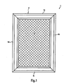
- an element 1 for a ceiling or wall paneling is visible, which is formed in the illustrated embodiment as a ceiling cassette for hanging in a carrier 2 (Fig. 3) of a conventional suspension system 3 for producing a suspended ceiling.
- the element 1 can also be used for producing a curtain wall cladding and connected to the wall via suitable supports.
- the element 1 can be used as a single piece for covers or the like.
- the element 1 comprises a frame 4 which is composed of rectilinear strips closed annularly, wherein the frame 4 in the illustrated embodiment has a rectangular shape with four sides 4a, 4b, 4c and 4d.
- the sides 4a to 4d are mitred in the illustrated embodiment and assembled in the usual way.
- the sides 4a to 4d made of metal, in particular of aluminum and are preferably cut from extruded profiles.
- the frame 4 is in standard sizes, e.g. 800 x 800 mm, 625 x 1250 mm or manufactured as a large field cover cassette with 1250 - 2500 mm, so that the element 1 fits with conventional suspension systems.
- the element 1 further contains a filling 5, which may consist of any material that is appropriate for the element 1.
- the filling 5 contains a perforated cover layer 5a (FIG. 3), for example a perforated plate, an expanded metal grid or the like, and an insulation 5b, which may be a conventional sound and / or heat insulation and on the visible side (Fig 1) facing away from the cover layer 5a is arranged.
- the filling 5 is clamped in the frame 4, wherein the clamping is preferably releasable, so that the filling can be optionally replaced.
- the clamping takes place via at least one clamping part 6.
- four clamping parts 6a, 6b, 6c and 6d are provided, each one Clamping part of a side 4a to 4d of the frame 4 is assigned.
- at least two opposite sides of the frame are preferably provided with in each case at least one clamping part.
- the clamping part 6 is formed like a strip and preferably shorter than the respectively associated side of the frame 4.
- the clamping part 6 is preferably made of metal, more preferably made of aluminum and is preferably made by extrusion and cut to the desired length.
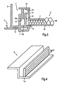
- the clamping member 6 has a substantially Z-shaped cross-section and includes a support surface 7 which is adapted to press on the filling 5.
- the frame 4 also includes a support surface 8, which faces the support surface 7 substantially parallel. Between the bearing surfaces 7 and 8, the filling 5 is clamped.
- the frame 4 further includes a contact surface 9 which extends transversely to the support surface 8, preferably at right angles thereto, and the positioning of the filling 5 is used, the possibly sharp edges of the cover 5a of the filling 5 safely at an angle between the two surfaces 8 and 9 are included.
- the contact surface 9 is located opposite a corresponding contact surface 10 on the clamping part 6, which can serve as a guide for the positioning of the clamping part 6.
- the clamping part 6 is releasably secured to the frame 4.
- a latching connection 11 is provided with a latching projection 11a and a latching recess 11b.
- the latching projection 11a is provided on the clamping part 6 and the latching recess 11b on the frame 4.
- the latching projection 11a is formed strip-shaped and protrudes substantially perpendicularly from a surface 12 on the clamping part 6, which extends substantially at right angles to the contact surface 10.
- the detent recess 11b is provided as a groove in the frame 4, which runs substantially parallel to the contact surface 9.
- the latching depression 11b also extends over the entire frame 4.
- the locking elements 13 include ribs 13a and grooves 13b, wherein the ribs 13a on the locking projection 11a and the grooves 13b in the locking recess 11b are arranged so that they can engage with each other when the locking projection 11a inserted into the locking recess 11b becomes.
- ribs 13 a are provided, which extend over the entire length of the strip-shaped latching projection 11 a, and are arranged parallel to and at a distance from each other, which is adapted to differences in thickness of the filling 5.
- a thickness adjustment is achieved, which makes it possible to clamp between the bearing surfaces 7 and 8 fills 5 of different thicknesses vibration-proof.
- fillings 5 can be clamped with a thickness between 3 and 20 mm.
- the plurality of ribs 13a may cooperate with just such a plurality of grooves 13b, but it is also possible to provide only one groove 13b and a plurality of ribs 13a or only one rib 13a and a plurality of grooves 13b.
- the frame 4 finally includes a support web 14, with which the element 1 can be placed on a support surface 2 a of the carrier 2.
- the required number of clamping parts 6 is fixed to the frame 4 by the clamping members 6 are pressed with their locking projections 11a in the locking recess 11b as far as it allows the thickness of the filling 5.
- the filling 5 between the bearing surfaces 7 and 8 clamped. If the clamping parts 6 necessary for secure fastening of the filling 5 are fastened to the frame 4, then the element can then be fastened in a customary manner on the carrier 2 of the suspension system 3, for example with the web 14 placed on the surface 2 a of the carrier 2.
- the inventively releasably formed connection between the clamping part 6 and the frame 4 via the locking connection 11 allows the filling 5 and the frame 4 can be replaced independently if, for example, the frame 4 or the filling 5 are damaged or the filling 5 against a new filling needs to be replaced.
- connection between the clamping parts and the frame can be solved differently.
- a connection is possible only by friction between a projection and a recess.
- the connection can continue to be provided only selectively and does not have to extend over the entire length of the clamping part. It can also be provided a plurality of locking projections and / or depressions.
- the invention is also applicable to frames with different profile or different construction. Finally, it may also be possible to clamp the filling only in a fixed slot in the frame.
Landscapes
- Engineering & Computer Science (AREA)
- Architecture (AREA)
- Civil Engineering (AREA)
- Structural Engineering (AREA)
- Physics & Mathematics (AREA)
- Electromagnetism (AREA)
- Connection Of Plates (AREA)
- Building Environments (AREA)
- Mutual Connection Of Rods And Tubes (AREA)
- Clamps And Clips (AREA)
- Transition And Organic Metals Composition Catalysts For Addition Polymerization (AREA)
- Developing Agents For Electrophotography (AREA)
Description
- Die Erfindung bezieht sich auf eine Deckenkassette zum Einsetzen in ein Abhängesystem.
- Aus der
US 3 455 080 ist eine Rahmenkonstruktion aus Kunststoff-Strangpressprofilen mit Klemmfunktion bekannt, die bevorzugt für Fenster einsetzbar ist. Die Befestigung der Glastafel erfolgt über ein dickenanpassbares Klemmsystem. Die Rahmenkonstruktion muss jedoch wie jeder Fensterrahmen in eine Wand oder dgl. eingesetzt werden. - Die
US 2 101 612 und dieUS 5 881 522 betreffen dickenanpassbare Klemmverbindungen für Paneele, die jedoch zum Verbinden benachbarter Füllungen direkt mit einem Träger verwendet werden. - Die
GB 2 317 145 - Ein Element für eine Decken- oder Wandverkleidung ist aus dem
DE 201 20 894 U1 bekannt. Das bekannte Element enthält einen Tragrahmen, der sich rund um eine im Wesentlichen rechteckige Öffnung erstreckt. Vom Tragrahmen steht ein umlaufender Randflansch im Wesentlichen senkrecht vor. Der Rahmen mit dem Randflansch besteht aus Metall, vorzugsweise aus Stahl. Am Randflansch ist ein Flächenelement der Füllung befestigt, das perforiert ist, beispielsweise als Lochblech oder Streckmetallgitter ausgebildet ist. Auch das Flächenelement der Füllung weist einen vorstehenden, umlaufenden Randflansch auf, der in der Art eines Schachteldeckels über den Randflansch des Rahmens geschoben wird. Die Befestigung erfolgt durch eine sogenannte Tox- oder Clinch-Verbindung, d.h. eine korrespondierende, bevorzugt hinterschnittene Prägung, die sich durch beide Randflansche erstreckt. - Decken- und/oder Wandelemente, wie sie beispielsweise für abgehängte Decken verwendet werden, müssen oft auch Isoliermaterial aufnehmen. Weiterhin müssen die Teile so miteinander verbunden werden, dass auch durch äußere Einflüsse, wie beispielsweise Zugluft, Schallwellen, der Betrieb der Klimaanlage oder dgl., keine Vibrationen bzw. Relativbewegungen zwischen den Teilen auftreten, die zu störenden Geräuschen führen könnten. Beim bekannten Tragrahmen ist beispielsweise eine Isolierung nicht so straff zu befestigen, dass ein Flattern mit Sicherheit unterbunden wird, da genügend Platz zum Einformen der Vertiefungen freigelassen werden muss.
- Der Erfindung liegt die Aufgabe zugrunde, eine Deckenkassette zu schaffen, bei der die Füllung sicher und vibrationsarm im Rahmen befestigt werden kann.
- Die Aufgabe wird durch die im Anspruch 1 angegebenen Merkmale gelöst.
- Durch die bei der erfindungsgemäßen Deckenkassette vorgesehene Klemmverbindung kann die Füllung auf einfache Weise, sicher, handhabungsfreundlich und gegen jede Relativbewegung geschützt im Rahmen befestigt werden. Darüber hinaus ist die Montage der Deckenkassette ohne Hilfsmittel, wie z.B. ein Prägewerkzeug, möglich und kann somit problemlos am Einsatzort und auch durch ungeübte Personen durchgeführt werden. Diverse An- und Auflageflächen definieren eine vorbestimmte Position für die Füllung und bilden Klemmflächen für die Klemmung. Durch die Dickenanpassung an die Dicke der Füllung kann das erfindungsgemäße Element ohne Anpassungsschwierigkeiten für Füllungen unterschiedlicher Dicke verwendet werden. Die Deckenkassette in genormter Größe kann problemlos in bereits vorhandene Träger in Form eines Abhängesystems eingesetzt werden.
- Vorteilhafte Weiterbildungen sind den Unteransprüchen zu entnehmen.
- Ist die Klemmung lösbar, so können Teile problemlos ausgetauscht werden.
- Klemmteil und Rahmen sind bevorzugt als getrennte Teile hergestellt, da dies die Handhabung weiter erleichtert.
- Ein leistenartig ausgebildetes Klemmteil ist wegen seiner über eine größere Fläche verteilten Klemmkraft bevorzugt.
- Bevorzugt ist das Klemmteil mit dem Rahmen über eine Rastverbindung verbindbar, die einfach und schnell herstellbar ist.
- Die Dickenanpassung erfolgt bevorzugt über eine Mehrzahl voneinander beabstandeter Rastsitze, da diese einfach in der Herstellung und einfach in der Handhabung sind.
- Die Ausgestaltung der Rastverbindung zwischen einer Nut und einer Leiste ist besonders kostengünstig herstellbar, und bewirkt einerseits einen sicheren Rastsitz und gleichzeitig eine Versteifung des Rahmens und des Klemmteils, so dass die Widerstandsfähigkeit gegen Vibrationen weiter erhöht wird.
- Bevorzugt sind Rahmen und/oder Klemmteil aus einem Aluminium-Strangpressprofil hergestellt.
- Die Klemmteile können je nach Erfordernis um den Rahmen herum verteilt werden, und sind bevorzugt an wenigstens zwei gegenüberliegenden Seiten des Rahmens vorgesehen.
- Wird das Klemmteil kürzer ausgebildet als eine anliegende Seite des Rahmens, so können Herstellungstoleranzen und/oder eine möglicherweise nicht korrekte Positionierung des Klemmteils ausgeglichen werden.
- Ein Ausführungsbeispiel der Erfindung wird nachfolgend anhand der Zeichnungen näher erläutert. Es zeigen:
- Fig. 1
- die Draufsicht auf die Sichtseite eines Elements einer erfindungsgemäßen Decken- oder Wandverkleidung,
- Fig. 2
- die Rückansicht des Elements gemäß Fig. 1,
- Fig. 3
- den Schnitt III-III aus Fig. 2 bei einem in einem Träger liegenden Element,
- Fig. 4
- eine perspektivische Ansicht eines Klemmteils, und
- Fig. 5
- eine perspektivische Ansicht eines Teils eines Rahmens.
- Aus den Fig. 1 bis 5 ist ein Element 1 für eine Decken- oder Wandverkleidung ersichtlich, das im dargestellten Ausführungsbeispiel als Deckenkassette zum Einhängen in einen Träger 2 (Fig. 3) eines üblichen Abhängesystems 3 zum Herstellen einer abgehängten Decke ausgebildet ist. Das Element 1 kann jedoch auch zum Herstellen einer vorgehängten Wandverkleidung verwendet und über geeignete Träger mit der Wand verbunden werden. Weiterhin kann das Element 1 als Einzelstück für Abdeckungen oder dgl. eingesetzt werden.
- Das Element 1 enthält einen Rahmen 4, der aus geradlinigen Leistenstücken geschlossen ringförmig zusammengesetzt ist, wobei der Rahmen 4 im dargestellten Ausführungsbeispiel eine rechtwinklige Form mit vier Seiten 4a, 4b, 4c und 4d aufweist. Die Seiten 4a bis 4d sind im dargestellten Ausführungsbeispiel auf Gehrung geschnitten und in üblicher Weise zusammengesetzt. Im dargestellten Ausführungsbeispiel bestehen die Seiten 4a bis 4d aus Metall, insbesondere aus Aluminium und sind bevorzugt aus Strangpressprofilen zurechtgeschnitten. Der Rahmen 4 ist in gängigen Normgrößen, so z.B. 800 x 800 mm, 625 x 1250 mm oder als Großfelddeckenkassette mit 1250 - 2500 mm gefertigt, so dass das Element 1 mit herkömmlichen Abhängesystemen zusammenpasst.
- Das Element 1 enthält weiterhin eine Füllung 5, die aus jedem Material bestehen kann, das für das Element 1 zweckmäßig gegeben ist. Im dargestellten Ausführungsbeispiel enthält die Füllung 5 eine perforierte Abdecklage 5a (Fig. 3), beispielsweise ein Lochblech, ein Streckmetallgitter oder dgl., und eine Isolierung 5b, die eine übliche Schall- und/oder Wärmeisolierung sein kann und auf der der Sichtseite (Fig. 1) abgewandten Seite der Abdecklage 5a angeordnet ist.
- Die Füllung 5 wird im Rahmen 4 festgeklemmt, wobei die Klemmung bevorzugt lösbar ist, damit die Füllung gegebenenfalls ausgetauscht werden kann.
- Die Klemmung erfolgt über wenigstens ein Klemmteil 6. Im dargestellten Ausführungsbeispiel sind vier Klemmteile 6a, 6b, 6c und 6d vorgesehen, wobei jeweils ein Klemmteil einer Seite 4a bis 4d des Rahmens 4 zugeordnet ist. Es ist jedoch auch möglich, einer Seite des Rahmens mehrere Klemmteile zuzuordnen bzw. nicht alle Seiten des Rahmens mit Klemmteilen zu versehen. Bevorzugt sind jedoch wenigstens zwei gegenüberliegende Seiten des Rahmens mit jeweils mindestens einem Klemmteil versehen.
- Das Klemmteil 6 ist leistenartig ausgebildet und bevorzugt kürzer als die jeweils zugeordnete Seite des Rahmens 4. Das Klemmteil 6 besteht bevorzugt aus Metall, insbesondere bevorzugt aus Aluminium und ist bevorzugt im Strangpressverfahren hergestellt und auf die gewünschte Länge geschnitten.
- Das Klemmteil 6 weist einen im Wesentlichen Z-förmigen Querschnitt auf und enthält eine Auflagefläche 7, die dazu ausgebildet ist, auf die Füllung 5 zu drücken. Der Rahmen 4 enthält ebenfalls eine Auflagefläche 8, die der Auflagefläche 7 im Wesentlichen parallel gegenüberliegt. Zwischen den Auflageflächen 7 und 8 wird die Füllung 5 eingeklemmt.
- Der Rahmen 4 enthält weiterhin eine Anlagefläche 9, die sich quer zur Auflagefläche 8 erstreckt, bevorzugt rechtwinklig dazu verläuft, und der Positionierung der Füllung 5 dient, wobei die möglicherweise scharfkantigen Begrenzungen der Abdecklage 5a der Füllung 5 sicher im Winkel zwischen den beiden Flächen 8 und 9 aufgenommen sind.
- Der Anlagefläche 9 liegt eine korrespondierende Anlagefläche 10 am Klemmteil 6 gegenüber, die als Führung für die Positionierung des Klemmteils 6 dienen kann.
- Das Klemmteil 6 wird am Rahmen 4 lösbar befestigt. Zu diesem Zweck ist eine Rastverbindung 11 mit einem Rastvorsprung 11 a und einer Rastvertiefung 11b vorgesehen. Im dargestellten Ausführungsbeispiel ist der Rastvorsprung 11a am Klemmteil 6 und die Rastvertiefung 11b am Rahmen 4 vorgesehen.
- Der Rastvorsprung 11a ist leistenförmig ausgebildet und steht im Wesentlichen senkrecht von einer Fläche 12 am Klemmteil 6 vor, die sich im Wesentlichen rechtwinklig zur Anlagefläche 10 erstreckt.
- Die Rastvertiefung 11b ist als Nut im Rahmen 4 vorgesehen, die im Wesentlichen parallel zur Anlagefläche 9 verläuft. Auch die Rastvertiefung 11b erstreckt sich über den gesamten Rahmen 4.
- Zwischen dem Rastvorsprung 11a und der Rastvertiefung 11b sind korrespondierende Rastelemente 13 vorgesehen. Im dargestellten Ausführungsbeispiel enthalten die Rastelemente 13 Rippen 13a und Rillen 13b, wobei die Rippen 13a am Rastvorsprung 11a und die Rillen 13b in der Rastvertiefung 11b so angeordnet sind, dass sie miteinander in Eingriff treten können, wenn der Rastvorsprung 11a in die Rastvertiefung 11 b eingesetzt wird.
- Es sind eine Vielzahl von Rippen 13a vorgesehen, die sich über die gesamte Länge des leistenförmigen Rastvorsprungs 11a erstrecken, sowie parallel und in einem Abstand zueinander angeordnet sind, der an Dickenunterschiede der Füllung 5 angepasst ist. Dadurch wird eine Dickenanpassung erreicht, die es gestattet, zwischen den Auflageflächen 7 und 8 Füllungen 5 der unterschiedlichsten Dicken vibrationssicher zu klemmen. Bevorzugt können Füllungen 5 mit einer Dicke zwischen 3 und 20 mm geklemmt werden.
- Die Vielzahl von Rippen 13a kann mit einer ebensolchen Vielzahl von Rillen 13b zusammenwirken, es ist jedoch auch möglich, nur eine Rille 13b und eine Vielzahl von Rippen 13a bzw. nur eine Rippe 13a und eine Vielzahl von Rillen 13b vorzusehen.
- Der Rahmen 4 enthält schließlich einen Auflagesteg 14, mit dem das Element 1 auf eine Auflagefläche 2a des Trägers 2 aufgelegt werden kann.
- Zur Montage des Elements 1 wird, bei abgenommenem Klemmteil 6, die Füllung 5, d.h. die Abdecklage 5a und gegebenenfalls die Isolierung 5b, in den Rahmen 4 eingesetzt, so dass die Füllung 5 auf der Auflagefläche 8 zu liegen kommt. Dann wird die benötigte Anzahl Klemmteile 6 am Rahmen 4 befestigt, indem die Klemmteile 6 mit ihren Rastvorsprüngen 11a in die Rastvertiefung 11b so weit hineingedrückt werden, wie es die Dicke der Füllung 5 zulässt. Dadurch wird die Füllung 5 zwischen den Auflageflächen 7 und 8 festgeklemmt. Sind die zum sicheren Befestigen der Füllung 5 notwendige Klemmteile 6 am Rahmen 4 befestigt, so kann das Element anschließend in üblicher Weise auf dem Träger 2 des Abhängesystems 3 befestigt werden, beispielsweise mit dem Steg 14 auf der Fläche 2a des Trägers 2 aufgelegt werden.
- Die erfindungsgemäß lösbar ausgebildete Verbindung zwischen dem Klemmteil 6 und dem Rahmen 4 über die Rastverbindung 11 gestattet es, dass die Füllung 5 und der rahmen 4 unabhängig voneinander ausgetauscht werden können, wenn beispielsweise der Rahmen 4 oder die Füllung 5 beschädigt sind oder die Füllung 5 gegen eine neue Füllung ausgetauscht werden muss.
- In Abwandlung des beschriebenen und gezeichneten Ausführungsbeispiels kann beispielsweise die Verbindung zwischen den Klemmteilen und dem Rahmen anders gelöst werden. So ist beispielsweise eine Verbindung nur über Reibung zwischen einem Vorsprung und einer Ausnehmung möglich. Die Verbindung kann weiterhin nur punktuell vorgesehen werden und muss sich nicht über die gesamte Länge des Klemmteils erstrecken. Es können weiterhin mehrere Rastvorsprünge und/oder Vertiefungen vorgesehen werden. Die Erfindung ist weiterhin auf Rahmen mit abweichendem Profil bzw. abweichender Konstruktion einsetzbar. Schließlich ist es unter Umständen auch möglich, die Füllung lediglich in einen fest eingestellten Schlitz im Rahmen festzuklemmen.
Claims (11)
- Deckenkassette zum Einsetzen in ein Abhängesystem (3), dadurch gekennzeichnet, dass die Deckenkassette einen Rahmen (4) , ein Klemmteil (6) und einer im Rahmen (4) mit Hilfe des mit dem Rahmen in Verbindung stehenden Klemmteils (6) dickenanpassbar festgeklemmten Füllung (5) aufweist, wobei der Rahmen (4) eine Auflageflache (8) für die Füllung (5) und das Klemmteil (6) eine Gegen-Auflagefläche (7) für die Füllung (5) enthält, die im Wesentlichen parallel zur Auflagefläche (8) am Rahmen (4) verläuft, so dass die Füllung (5) vibrationsarm im Rahmen (4) festgeklemmt ist, und dass der Rahmen (4) einen Auflagesteg (14) zum Auflegen auf einen Träger (2) des Abhängesystems (3) aufweist.
- Deckenkassette nach Anspruch 1, dadurch gekennzeichnet, dass die Klemmung lösbar ist.
- Deckenkassette nach Anspruch 1 oder 2, dadurch gekennzeichnet, dass das Klemmteil (6) und der Rahmen (4) als getrennte Teile hergestellt sind.
- Deckenkassette nach einem der Ansprüche 1 bis 3, dadurch gekennzeichnet, dass das Klemmteil (6) leistenartig ausgebildet ist.
- Deckenkassette nach einem der Ansprüche 1 bis 4, dadurch gekennzeichnet, dass die Verbindung zwischen dem Klemmteil (6) und dem Rahmen (4) eine Rastverbindung (11) enthält.
- Deckenkassette nach Anspruch 5, dadurch gekennzeichnet, dass die Rastverbindung (11) einen Rastvorsprung (11a) und eine korrespondierende Rastvertiefung (11 b) enthält, zwischen denen eine Mehrzahl in Dickenrichtung der Füllung (5) voneinander beabstandeter Rastsitze (13) vorgegeben sind.
- Deckenkassette nach Anspruch 5 oder 6, dadurch gekennzeichnet, dass die Rastverbindung (11) eine Nut (11b) und eine Leiste (11a) aufweist, die in der Nut (11b) aufnehmbar ist.
- Deckenkassette nach einem der Ansprüche 1 bis 7, dadurch gekennzeichnet, dass der Rahmen (4) aus einem Aluminium-Strangpressprofil besteht.
- Deckenkassette nach einem der Ansprüche 1 bis 8, dadurch gekennzeichnet, dass das Klemmteil (6) aus einem Aluminium-Strangpressprofil besteht.
- Deckenkassette nach einem der Ansprüche 1 bis 9, dadurch gekennzeichnet, dass der Rahmen (4) an wenigsten zwei gegenüberliegenden Seiten mit jeweils wenigstens einem Klemmteil (6) versehen ist.
- Deckenkassette nach einem der Ansprüche 1 bis 10, dadurch gekennzeichnet, dass das Klemmteil (6) kürzer ist als eine anliegende Seite (4a,b,c,d) des Rahmens (4).
Applications Claiming Priority (1)
| Application Number | Priority Date | Filing Date | Title |
|---|---|---|---|
| DE202004012119U DE202004012119U1 (de) | 2004-08-03 | 2004-08-03 | Decken- und Wandverkleidungselement |
Publications (2)
| Publication Number | Publication Date |
|---|---|
| EP1635006A1 EP1635006A1 (de) | 2006-03-15 |
| EP1635006B1 true EP1635006B1 (de) | 2007-08-22 |
Family
ID=35266765
Family Applications (1)
| Application Number | Title | Priority Date | Filing Date |
|---|---|---|---|
| EP05004720A Expired - Lifetime EP1635006B1 (de) | 2004-08-03 | 2005-03-03 | Deckenkassette |
Country Status (3)
| Country | Link |
|---|---|
| EP (1) | EP1635006B1 (de) |
| AT (1) | ATE371068T1 (de) |
| DE (2) | DE202004012119U1 (de) |
Families Citing this family (1)
| Publication number | Priority date | Publication date | Assignee | Title |
|---|---|---|---|---|
| CN102191841A (zh) * | 2011-04-13 | 2011-09-21 | 泗阳浙阳新型保温防水材料有限公司 | 装饰板扣件 |
Family Cites Families (4)
| Publication number | Priority date | Publication date | Assignee | Title |
|---|---|---|---|---|
| US2101612A (en) * | 1936-08-22 | 1937-12-07 | Sealed Joint Products Co Inc | Panel mounting |
| US3455080A (en) * | 1964-09-25 | 1969-07-15 | Goodrich Co B F | Plastic extrusions,methods of using the same,and structures formed therewith |
| US5694727A (en) * | 1992-08-12 | 1997-12-09 | Commercial And Architectural Products, Inc. | Wall system providing an array of individual panels |
| GB9616500D0 (en) * | 1996-08-06 | 1996-09-25 | Dove Holdings Plc | Decorating panels |
-
2004
- 2004-08-03 DE DE202004012119U patent/DE202004012119U1/de not_active Expired - Lifetime
-
2005
- 2005-03-03 DE DE502005001289T patent/DE502005001289D1/de not_active Expired - Lifetime
- 2005-03-03 AT AT05004720T patent/ATE371068T1/de not_active IP Right Cessation
- 2005-03-03 EP EP05004720A patent/EP1635006B1/de not_active Expired - Lifetime
Also Published As
| Publication number | Publication date |
|---|---|
| ATE371068T1 (de) | 2007-09-15 |
| EP1635006A1 (de) | 2006-03-15 |
| DE202004012119U1 (de) | 2005-12-22 |
| DE502005001289D1 (de) | 2007-10-04 |
Similar Documents
| Publication | Publication Date | Title |
|---|---|---|
| EP0727853B1 (de) | Rahmenkonstruktion für Gestelle und Gehäuse von Baugruppenträgern und Schränken zur Aufnahme von elektrischen und/oder elektronischen Bauteilen | |
| EP1344712B1 (de) | Verbundbauteil, insbesondere Fahrzeuganbauteil oder Fahrzeugpaneel | |
| DE202012008857U1 (de) | Vorwandmontagesystem | |
| DE112019007932T5 (de) | Positioniereinheit für Nutensteine | |
| DE102011000991A1 (de) | Wandhalterung für ein selbsttragendes, plattenförmiges Bauteil, insbesondere für ein Vordach, und Montageverfahren | |
| EP1233118B1 (de) | Fassadenverkleidung | |
| EP1635006B1 (de) | Deckenkassette | |
| DD250155A5 (de) | Fenster, welches einen rahmen mit einer nut fuer ein inneres plattenfoermiges element enthaelt | |
| DE102014208303A1 (de) | Befestigungsvorrichtung zur Befestigung von Photovoltaikmodulen | |
| DE102013003823A1 (de) | Sanitärarmatur mit einer Rosette | |
| WO2012084387A1 (de) | Trockenbauwand | |
| EP1647649A2 (de) | Fassadenbefestigungssystem | |
| EP3822562B1 (de) | Klimaschrank | |
| EP3098361B1 (de) | Flächenkonstruktion für die ausbildung von wänden, trennwänden, fassaden und dgl | |
| EP2639911A2 (de) | Montageelement für Geräteeinbaukanäle, Geräteeinbaukanal mit einem derartigen Montageelement sowie Verfahren zur Montage eines derartigen Montageelements in einen Geräteeinbaukanal | |
| DE102014205819A1 (de) | System zur Aufnahme von Lichtmodulen sowie Verfahren für dessen Herstellung | |
| DE102016104405A1 (de) | Verfahren zur Montage einer Pfosten-Riegel-Konstruktion und Montagehilfe | |
| EP4343099B1 (de) | Halterung eines plattenförmigen elements | |
| DE60202279T2 (de) | Rahmen zum festhalten einer plattenförmigen tafel | |
| EP2549040B2 (de) | Kombination aus Tragstruktur und Laufwagen für eine Schiebetür | |
| DE102006060455B4 (de) | Befestigungssystem zur Rand- und/oder Eckbefestigung von wenigstens einem Paneel | |
| EP0409029A1 (de) | Profil zur Halterung von Deckenplatten | |
| DE202006020674U1 (de) | Profilverbinder | |
| EP0738806A1 (de) | Anschlussfutter für einen Fensterrahmen | |
| EP1593786B1 (de) | Befestigungsvorrichtung für Geräteeinsätze in Arbeitsplatten |
Legal Events
| Date | Code | Title | Description |
|---|---|---|---|
| PUAI | Public reference made under article 153(3) epc to a published international application that has entered the european phase |
Free format text: ORIGINAL CODE: 0009012 |
|
| AK | Designated contracting states |
Kind code of ref document: A1 Designated state(s): AT BE BG CH CY CZ DE DK EE ES FI FR GB GR HU IE IS IT LI LT LU MC NL PL PT RO SE SI SK TR |
|
| AX | Request for extension of the european patent |
Extension state: AL BA HR LV MK YU |
|
| 17P | Request for examination filed |
Effective date: 20060830 |
|
| GRAP | Despatch of communication of intention to grant a patent |
Free format text: ORIGINAL CODE: EPIDOSNIGR1 |
|
| AKX | Designation fees paid |
Designated state(s): AT CH DE LI |
|
| RTI1 | Title (correction) |
Free format text: CEILING ELEMENT |
|
| GRAS | Grant fee paid |
Free format text: ORIGINAL CODE: EPIDOSNIGR3 |
|
| GRAA | (expected) grant |
Free format text: ORIGINAL CODE: 0009210 |
|
| AK | Designated contracting states |
Kind code of ref document: B1 Designated state(s): AT CH DE LI |
|
| RIN1 | Information on inventor provided before grant (corrected) |
Inventor name: FISCHER, WILLIBALD |
|
| REG | Reference to a national code |
Ref country code: CH Ref legal event code: EP |
|
| REF | Corresponds to: |
Ref document number: 502005001289 Country of ref document: DE Date of ref document: 20071004 Kind code of ref document: P |
|
| PLBE | No opposition filed within time limit |
Free format text: ORIGINAL CODE: 0009261 |
|
| STAA | Information on the status of an ep patent application or granted ep patent |
Free format text: STATUS: NO OPPOSITION FILED WITHIN TIME LIMIT |
|
| 26N | No opposition filed |
Effective date: 20080526 |
|
| PG25 | Lapsed in a contracting state [announced via postgrant information from national office to epo] |
Ref country code: AT Free format text: LAPSE BECAUSE OF NON-PAYMENT OF DUE FEES Effective date: 20080303 |
|
| REG | Reference to a national code |
Ref country code: CH Ref legal event code: PL |
|
| PG25 | Lapsed in a contracting state [announced via postgrant information from national office to epo] |
Ref country code: CH Free format text: LAPSE BECAUSE OF NON-PAYMENT OF DUE FEES Effective date: 20090331 Ref country code: LI Free format text: LAPSE BECAUSE OF NON-PAYMENT OF DUE FEES Effective date: 20090331 |
|
| PGFP | Annual fee paid to national office [announced via postgrant information from national office to epo] |
Ref country code: DE Payment date: 20100429 Year of fee payment: 6 |
|
| PG25 | Lapsed in a contracting state [announced via postgrant information from national office to epo] |
Ref country code: DE Free format text: LAPSE BECAUSE OF NON-PAYMENT OF DUE FEES Effective date: 20111001 |
|
| REG | Reference to a national code |
Ref country code: DE Ref legal event code: R119 Ref document number: 502005001289 Country of ref document: DE Effective date: 20111001 |