EP1635012A2 - Zylinderschloss - Google Patents
Zylinderschloss Download PDFInfo
- Publication number
- EP1635012A2 EP1635012A2 EP05018596A EP05018596A EP1635012A2 EP 1635012 A2 EP1635012 A2 EP 1635012A2 EP 05018596 A EP05018596 A EP 05018596A EP 05018596 A EP05018596 A EP 05018596A EP 1635012 A2 EP1635012 A2 EP 1635012A2
- Authority
- EP
- European Patent Office
- Prior art keywords
- plug
- tumbler
- pin
- tumbler pin
- drive
- Prior art date
- Legal status (The legal status is an assumption and is not a legal conclusion. Google has not performed a legal analysis and makes no representation as to the accuracy of the status listed.)
- Withdrawn
Links
Images





Classifications
-
- E—FIXED CONSTRUCTIONS
- E05—LOCKS; KEYS; WINDOW OR DOOR FITTINGS; SAFES
- E05B—LOCKS; ACCESSORIES THEREFOR; HANDCUFFS
- E05B19/00—Keys; Accessories therefor
- E05B19/0017—Key profiles
- E05B19/0023—Key profiles characterized by variation of the contact surface between the key and the tumbler pins or plates
-
- E—FIXED CONSTRUCTIONS
- E05—LOCKS; KEYS; WINDOW OR DOOR FITTINGS; SAFES
- E05B—LOCKS; ACCESSORIES THEREFOR; HANDCUFFS
- E05B27/00—Cylinder locks or other locks with tumbler pins or balls that are set by pushing the key in
- E05B27/0039—Cylinder locks or other locks with tumbler pins or balls that are set by pushing the key in with pins which slide and rotate about their axis
-
- E—FIXED CONSTRUCTIONS
- E05—LOCKS; KEYS; WINDOW OR DOOR FITTINGS; SAFES
- E05B—LOCKS; ACCESSORIES THEREFOR; HANDCUFFS
- E05B27/00—Cylinder locks or other locks with tumbler pins or balls that are set by pushing the key in
- E05B27/0082—Side bar locking
-
- Y—GENERAL TAGGING OF NEW TECHNOLOGICAL DEVELOPMENTS; GENERAL TAGGING OF CROSS-SECTIONAL TECHNOLOGIES SPANNING OVER SEVERAL SECTIONS OF THE IPC; TECHNICAL SUBJECTS COVERED BY FORMER USPC CROSS-REFERENCE ART COLLECTIONS [XRACs] AND DIGESTS
- Y10—TECHNICAL SUBJECTS COVERED BY FORMER USPC
- Y10T—TECHNICAL SUBJECTS COVERED BY FORMER US CLASSIFICATION
- Y10T70/00—Locks
- Y10T70/70—Operating mechanism
- Y10T70/7441—Key
- Y10T70/7486—Single key
- Y10T70/7508—Tumbler type
- Y10T70/7559—Cylinder type
- Y10T70/7565—Plural tumbler sets
-
- Y—GENERAL TAGGING OF NEW TECHNOLOGICAL DEVELOPMENTS; GENERAL TAGGING OF CROSS-SECTIONAL TECHNOLOGIES SPANNING OVER SEVERAL SECTIONS OF THE IPC; TECHNICAL SUBJECTS COVERED BY FORMER USPC CROSS-REFERENCE ART COLLECTIONS [XRACs] AND DIGESTS
- Y10—TECHNICAL SUBJECTS COVERED BY FORMER USPC
- Y10T—TECHNICAL SUBJECTS COVERED BY FORMER US CLASSIFICATION
- Y10T70/00—Locks
- Y10T70/70—Operating mechanism
- Y10T70/7441—Key
- Y10T70/7486—Single key
- Y10T70/7508—Tumbler type
- Y10T70/7559—Cylinder type
- Y10T70/7571—Concentric tumblers
-
- Y—GENERAL TAGGING OF NEW TECHNOLOGICAL DEVELOPMENTS; GENERAL TAGGING OF CROSS-SECTIONAL TECHNOLOGIES SPANNING OVER SEVERAL SECTIONS OF THE IPC; TECHNICAL SUBJECTS COVERED BY FORMER USPC CROSS-REFERENCE ART COLLECTIONS [XRACs] AND DIGESTS
- Y10—TECHNICAL SUBJECTS COVERED BY FORMER USPC
- Y10T—TECHNICAL SUBJECTS COVERED BY FORMER US CLASSIFICATION
- Y10T70/00—Locks
- Y10T70/70—Operating mechanism
- Y10T70/7441—Key
- Y10T70/7486—Single key
- Y10T70/7508—Tumbler type
- Y10T70/7559—Cylinder type
- Y10T70/7588—Rotary plug
- Y10T70/7593—Sliding tumblers
- Y10T70/7599—Transverse of plug
- Y10T70/7605—Pin tumblers
-
- Y—GENERAL TAGGING OF NEW TECHNOLOGICAL DEVELOPMENTS; GENERAL TAGGING OF CROSS-SECTIONAL TECHNOLOGIES SPANNING OVER SEVERAL SECTIONS OF THE IPC; TECHNICAL SUBJECTS COVERED BY FORMER USPC CROSS-REFERENCE ART COLLECTIONS [XRACs] AND DIGESTS
- Y10—TECHNICAL SUBJECTS COVERED BY FORMER USPC
- Y10T—TECHNICAL SUBJECTS COVERED BY FORMER US CLASSIFICATION
- Y10T70/00—Locks
- Y10T70/70—Operating mechanism
- Y10T70/7441—Key
- Y10T70/7486—Single key
- Y10T70/7508—Tumbler type
- Y10T70/7559—Cylinder type
- Y10T70/7588—Rotary plug
- Y10T70/7593—Sliding tumblers
- Y10T70/7599—Transverse of plug
- Y10T70/7605—Pin tumblers
- Y10T70/761—Rotatable pins [e.g., MEDECO lock]
-
- Y—GENERAL TAGGING OF NEW TECHNOLOGICAL DEVELOPMENTS; GENERAL TAGGING OF CROSS-SECTIONAL TECHNOLOGIES SPANNING OVER SEVERAL SECTIONS OF THE IPC; TECHNICAL SUBJECTS COVERED BY FORMER USPC CROSS-REFERENCE ART COLLECTIONS [XRACs] AND DIGESTS
- Y10—TECHNICAL SUBJECTS COVERED BY FORMER USPC
- Y10T—TECHNICAL SUBJECTS COVERED BY FORMER US CLASSIFICATION
- Y10T70/00—Locks
- Y10T70/70—Operating mechanism
- Y10T70/7441—Key
- Y10T70/778—Operating elements
- Y10T70/7791—Keys
- Y10T70/7881—Bitting
Definitions
- the present invention relates to a cylinder lock device.
- JP-A-2003-129710 discloses a cylinder lock using pin tumblers.
- the cylinder lock of JP-A-2003-129710 is formed by housing individual pin tumblers in a plug and a cylinder case. When a genuine unlocking key is inserted into the plug, boundaries of the pin tumblers move to a turning boundary of the plug in accordance with a depth of unlocking code forming recesses formed in the unlocking key, so that the key can be turned in the plug.
- JP-B-07-030641 discloses a cylinder lock, in which tumbler pins in a plug are turned by a predetermined angle on moving center lines by an unlocking key so that the locked/unlocked state is determined according to turning positions.
- the tumbler pins are cut into V-shape at their leading ends and are held turnably on longitudinal center lines.
- the unlocking key is provided with slits, in which the slits to have the leading ends of the tumbler pins fitted therein are arrayed at angles of intersection varied with respect to the longitudinal axis.
- the cylinder lock of JP-B-07-030641 is defective in that the unlocking key can be copied merely by tracing the cut angles of the original key.
- One or more embodiments of the present invention provide a cylinder lock capable of increasing different locking codes.
- one or more embodiments of the present invention provide a cylinder lock device, for which an unlocking key is hard to copy.
- a cylinder lock is provided with: a cylinder case; a cylindrical plug turnably inserted into the cylinder case; a tumbler pin held in the plug and enabled to proceed into the cylinder case and to turn on a moving direction center axis; a drive pin held in the cylinder case and enabled to proceed into the plug and to turn on the moving direction center axis; a first cylindrical curvature face formed at an end portion of the tumbler pin to contact with the drive pin and having a radius of curvature equal to a diameter of the plug and a center of curvature on a rotational center line of the plug; and a second cylindrical curvature face formed on an end portion of the drive pin to contact with the tumbler pin and coextending with the first cylindrical curvature faces.
- the cylinder lock is formed by inserting the plug having the tumbler pins fitted therein, turnably into the cylinder case having the tumbler pins fitted therein.
- the tumbler pins and the drive pins are so arranged in tandem at an initial turning position of the plug that the tumbler pins can enter into the cylinder case while moving the drive pins backward and that the drive pins can enter the plug while pushing the tumbler pins.
- the drive pins and the tumbler pins are provided, at the end portions on the side of the tumbler pins and at the end portions on the side of the drive pins, respectively, with curvature faces substantially coincident with the turning boundary cylindrical faces between the plug and the cylinder case.
- the two members are so arranged in tandem as to contact with the curvature face.
- the plug can turn with respect to the cylinder case. If the tumbler pins and the drive pins turn horizontally at that position, on the other hand, the leading ends of the drive pins proceed to the plug side over the turning boundary of the plug, and the leading ends of the tumbler pins also proceed to the side of the cylinder case. As a result, the turning boundary is closed so that the plug cannot be turned.
- the moving direction center axes are offset from the turning center of the plug. This enlarges the height difference of the tumbler pins due to the turns. Even at a small turning angle, therefore, the height for closing the turning boundary between the plug and the cylinder case is increased to improve the locking reliability.
- the operation to turn the tumbler pins is performed by inserting the plug into the unlocking key.
- This unlocking key is provided with unlocking code forming recesses for turning the tumbler pins to predetermined turning positions.
- unlocking code forming recesses and the corresponding leading end shapes of the tumbler pins a suitable combination can be adopted if the tumbler pins can be guided to predetermined horizontal turning positions.
- the unlocking code forming recesses are formed into grooves for fitting those leading ends so that the angle of the grooves determines the turning positions of the tumbler pins.
- the cylinder lock is further provided with drive portions formed at the end portions of the tumbler pins on the sides of key insertion portions and having conical faces gradually reduced in diameter toward the leading ends.
- a rotational centers of the conical faces are offset from the moving direction center axis.
- the drive portions turn the tumbler pins when they are pushed onto conical recesses having rotational centers substantially aligned to the rotational centers of the conical faces of the drive portions.
- the drive portions move on the circumferential walls of the unlocking code forming recesses to the final contact positions while sequentially changing the contact positions from the contact starting point.
- the contact starting points are indefinite, because they are determined by the initial turning positions of the tumbler pins, and are unknown because the final contact points are determined by the set codes. Therefore, all the circumferential walls have to be copied, thereby to make the copying works difficult.
- a cylinder lock device provided with: a cylinder lock having tumbler pins housed movably in a plug and having its locked/unlocked state determined by turning positions around the moving direction center axes of the tumbler pins; and an unlocking key adapted to be inserted into the plug and having unlocking code forming recesses for determining the turning positions of the tumbler pins at code decision positions.
- the tumbler pins are provided at their leading endportions with conical faces as outer circumferences gradually reduced in diameter toward the leading ends and having rotational centers offset from the moving direction center axes.
- the unlocking code forming recesses are provided with conical faces as inner circumferences having rotational centers substantially aligned with those of the conical faces of the drive portions. At the code decision positions, the conical faces of the drive portions are forced to contact with the conical faces of the unlocking code forming recesses thereby to determine the turning positions of the tumbler pins.
- the invention does not exclude the determination of the locked/unlocked state by the movement along the moving direction center axes of the tumbler pins but contains not only the case, in which the different locking codes are achieved only by the turning positions of the tumbler pins, but also the case, in which both the turning positions and the moving strokes of the tumbler pins are the factors for generating the different locking codes.
- a variety of constitutions can be adopted as the method for determining the locked/unlocked state according to the turning positions of the tumbler pins. These adoptions can be achieved by providing the retracting passage of a side bar closing the turning boundary between the plug and the cylinder case, for example, with the turns of the tumbler pins. Moreover, the determination of the locked/unlocked state can be realized by a constitution, in which the turning boundary of the plug is opened only when the tumbler pins are at the predetermined turning positions.
- the drive portions of the tumbler pins in the plug come into abutment against the circumferential walls of the unlocking code forming recesses.
- the drive portions are provided with slope sides of conical faces gradually reduced in diameter toward the leading ends and having rotational centers offset from the moving direction center axes.
- the unlocking code forming recesses are formed of conical inner faces having rotational centers substantially aligned with those of the conical faces of the drive portions.
- the moving direction center axes of the tumbler pins, i.e., the horizontal turning centers do not coincide with the rotational centers of rotating cones. If the slope sides are pushed, therefore, horizontal turning torques are created in the tumbler pins so that the tumbler pins horizontally turn to predetermined positions.
- the slope sides move on the circumferential walls of the unlocking code forming recesses to the final contact positions while sequentially changing the contact positions from the contact starting point.
- the contact starting points are indefinite, because they are determined by the initial turning positions of the tumbler pins, and are unknown because the final contact points are determined by the set codes. Therefore, all the circumferential walls have to be copied, thereby to make the copying works difficult.
- the component force as established on a generating line of a rotating cone, in the turning direction is utilized for turning the tumbler pins.
- the contact segments or the slope sides
- the slope sides may be exemplified by ridges of a polyhedron.
- the slope sides are formed into the conical faces of rotating cones, they abut in face-to-face relation against the circumferential walls of the unlocking code forming recesses so that their actions are smooth.
- the slope sides may have curved lines such as arcs.
- a cylinder lock is provided with: a plug including a key insertion portion longitudinally thereof at a center portion and tumbler pins movable in directions into and out of the key insertion portion and turnable on the moving direction center; a cylinder case having the plug turnably inserted thereinto and including drive pins for applying an urging force toward the protruding side of the key insertion portions to the tumbler pins when the plug is at the initial turning position; and a locking portion for opening/closing the turning boundary between the plug and the cylinder case in accordance with the turning positions of the tumbler pins.
- the tumbler pins are provided, at their end positions on the side of the key insertion portions, with drive portions having conical faces gradually reduced in diameter toward the leading ends and having rotational centers offset from moving direction center axes.
- the locking portion may be modified in various manners by utilizing the side bars.
- the locking portion includes contact side end portions between the tumbler pins and the drive pins, and the contact end face between the tumbler pins and the drive pins is formed of the curvature face coincident with the cylindrical turning boundary between the plug and the cylinder case.
- the side bar or the like can be eliminated to simplify the constitution.
- anunlocking key to be inserted into a plug of a cylinder lock in which tumbler pins are movably housed in the plug so that a locked/unlocked state is determined by the turning positions of the tumbler pins on the moving direction center axes, comprises: unlocking code forming recesses, and the unlocking code forming recesses are formed into conical faces having rotational centers in a plurality of rows parallel to the insertion direction of the unlocking key into the plug.
- the rotational centers of the conical faces of the unlocking code forming recesses are arranged on one selected in a predetermined order from three rows, which are aligned at their center with the projection line in the moving direction of the tumbler array.
- Fig. 1A to Fig. 2 show a cylinder lock 10, which is fixed on a door body (D) and used for operating the lock body in the door body (D).
- the cylinder lock 10 is formed by inserting a plug 1 turnably into a cylinder case 8, and a cylindrical cover 13 is fitted in the front end portion of the cylinder case 8.
- the cylindrical cover 13 can be moved by a turning operation to the surface side of the door body (D).
- the cylindrical cover can be fastened to cover a mounting hole 14 opened in the door body (D), as shown in Fig. 1B.
- a cap member 1a is fitted in the front end of the Plug 1.
- a key insertion portion 6 which longitudinally extends of the plug 1.
- tumbler insertion holes 15 which are opened at one end in the key insertion portion 6 and at the other end in the outer circumference of the plug 1.
- Each tumbler insertion hole 15 is formed into a hole having a circular section and are provided with two tumbler turn restricting projections 15a near the key insertion portion 6 and at two symmetric positions with respect to a center axis (as will be described as a moving direction center axis 11 because it is aligned with the moving direction center axis of tumbler pin 2) of the tumbler insertion hole 15.
- each tumbler insertion hole 15 is arranged normal to the widthwise center plane of the key insertion portion 6 and is arrayed to belong to any of a plurality of planes (i.e. , tumbler row planes) parallel to the turning center of the plug 1.
- Equivalent spacings (Pt) are set between the key insertion portions 6 in the common tumbler row plane (St).
- totally three tumbler row planes (St1 to 3) are set two on one side and one on the other side with respect to the widthwise center plane of the key insertion portion 6.
- one plane (St1) on the other side contains a turning center (Cp) of the plug
- two planes (St2 and St3) of one side are arranged at symmetric positions with respect to the tumbler row plane (St1) on the aforementioned other side.
- the two planes (St2 and St3) on one side are offset by ( ⁇ ) from the turning center (Cp) of the plug 1.
- the aforementioned one plane (St1) on the other side is employed for constituting the master key system.
- This tumbler row plane (St1) employs the well-known tumbler pin (as will be called the "auxiliary tumbler pin 2' "), which has two generally frustum-conical ends to constitute an auxiliary locking portion 9' together with the later-described auxiliary drive pin 7'.
- the auxiliary tumbler pin 2' detects only the depth of unlocking code forming recesses 3 of the later-described unlocking key 4 thereby to decide the code.
- the turn restricting projection 15a is not provided in the tumbler insertion hole 15, into which the auxiliary tumbler pin 2' is to be inserted.
- the tumbler pins 2 to be arrayed in the tumbler row planes (St2 and St3) on one side are shown in Fig. 5A to Fig. 5D.
- This tumbler pin 2 has a drive portion 5 having an outer circumference of a frustum-conical face on one end (For clarifying the description, the side on which the drive portion 5 is formed will be located on the lower side, and the opposite side will be located on the upper side.).
- the rotational center Ct i.e., the rotational center at the time of rotating a generating line to acquire the conical shape
- ⁇ predetermined spacing
- the drive portion 5 has opposed chords cut off to have sections linearly symmetric with respect to the moving direction center axis 11, so that its opposed flat faces 5a are parallel to the plane which contains both the rotational center (Ct) of the cone and the moving direction center axis 11 of the tumbler pin 2.
- the flat faces 5a abut against the tumbler turn regulating projections 15a, when the key is inserted into the tumbler insertion hole 15, thereby to restrict the turning range of the tumbler pin 2.
- a cylindrical curvature face 2a (i.e., a first cylindrical curvature face 2a).
- This cylindrical curvature face 2a has a radius of curvature (R) equal to the radius of the plug 1 and a center of curvature aligned with the turning center line (Cp) of the plug 1 when the curvature face coextends with the outer circumference of the plug 1.
- the length factors are set with the same shape but different lengths as that of the aforementioned tumbler pins 2, and turning factors for the different locking codes are added between the tumbler pins having identical length factors.
- the turning factors are made by varying the angle of intersection (i.e., the angle ⁇ in Fig. 5D) on the plane (i,e., the projection plane) normal to the moving direction center axis 11 between the plane containing the rotational center (Ct) of the cone of the drive portion 5 and the moving direction center axis 11 and the plane containing the center line of the aforementioned cylindrical curvature face 2a.
- the angle ⁇ can be varied from 0 degrees to 360 degrees in Fig. 5D.
- six kinds of locking codes are set to 0 degrees, as shown in Fig. 5C, clockwise to 45 degrees (Fig. 5D), to 135 degrees, as vertically inverted from Fig. 5D, to 180 degrees, as vertically inverted from Fig. 5C, and to 225 and 315 degrees, as clockwise/counter-clockwise reversed from the former two.
- the identical tumbler pins 2 are utilized as those having the different turning factors turned by 180 degrees, when they are employed at the symmetric positions.
- the drive pins 7 and 7' which have diameters substantially equal to those of the tumbler pin 2 and the auxiliary tumbler pin 2'.
- the drive pins 7 and 7' confront the tumbler pins 2 and 2' , respectively, when the plug 1 is at the initial turning position (i.e., at the locking turning position) so that they can proceed into the tumbler insertion holes 15 on the side of the plug 1.
- the tumbler pins 2 and 2' can also proceed into the cylinder case 8.
- the individual drive pins 7 are urged to the center portion of the plug 1 by compression springs 16.
- a cylindrical curvature face i.e., a second cylindrical curvature face
- the well-known one having a frustum-conical shape at its leading end is employed as the auxiliary drive pin 7' corresponding to the auxiliary tumbler pin 2'.
- the boundaries between the tumbler pins 2 and the drive pins 7 constitute locking portions 9, and the boundaries between the auxiliary tumbler pins 2' and the auxiliary drive pins 7' constitute the auxiliary locking portions 9'.
- FIG. 3 An unlocking key 4 for constituting the cylinder lock device together with the cylinder lock 10 thus constituted is shown in Fig. 3.
- the unlocking key 4 is formed to have a grip portion 4b at one end of a key blade portion 4a.
- the plural unlocking code forming recesses 3 are formed in a dimple shape in the two faces of the keyblade portion 4a.
- the key blade portion 4a is formed into a point-symmetry shape with respect to the intersection between the thickness center and the widthwise center while including the portion to form the unlocking code forming recesses 3.
- reference numerals 4c designate guide grooves, in which projections 1b formed on the plug 1 on the side of the key insertion portion 6 thereby to regulate the inserted position of the key in the plug 1.
- the unlocking code forming recesses corresponding to the auxiliary tumbler pins 2' are formed to confirm the coincidence between the depth of the unlocking code forming recesses 3' and the auxiliary tumbler pins 2' by an abutment of the leading ends of the auxiliary tumblerpins 2' against bottomwall portions 3a'.
- the auxiliary pin unlocking code forming recesses 3' are formed by cutting the positions, where the centers of the bottom wall portions 3a' are aligned to the moving direction center axes 11 of the auxiliary tumbler pins 2', in the dimple shapes at the positions (i.e., the code decision positions), in which the unlocking key 4 is inserted to a normal position.
- the unlocking code forming recesses 3 corresponding to the tumbler pins 2 are formed in the dimple shape having a circumferential wall for applying a turning torque to the tumbler pins 2 through the conical face in the drive portions 5 of the aforementioned tumbler pins 2.
- the circumferential wall which may abut against the drive portions 5 of the tumbler pins 2, is formed by the same conical faces as those of the drive portions 5.
- these unlocking code forming recesses 3 are set in a plurality of kinds having only different depths corresponding to the change in the lengths of the tumbler pins 2.
- the positions of the unlocking code forming recesses 3 are so set even in the shallowest codes having the minimum area in the concave areas on the surface of the unlocking key 4 that the rotational center (i.e., the frustum-conical, face in this embodiment having the frustum-conical face) of the cone may be contained in the aforementioned recessed areas.
- the unlocking code forming recesses 3 are arranged in the following manner.
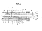
- totally six reference lines (L21, L22, L23, L31, L32 and L33) are so set three on the side faces of the unlocking key 4 as to correspond to the common tumbler row plane (St), as shown in Fig. 6 (although letters Lmn designate an n-th reference line of the tumbler row plane Stm).
- Reference lines L are straight lines parallel to the longitudinal direction of the unlocking key 4 and are arranged at an equal spacing (p) in the widthwise direction.
- the unlocking code forming recesses 3 are so arranged that the rotational centers of the conical faces may lie on any of the aforementioned reference lines (L) and that the spacing (Pt) between the adjoining rotational centers may be equal to that (Pt) between the adjoining tumbler insertion holes 15 in the common tumbler row plane (St) of the plug 1.
- the unlocking code forming recesses 3 on the reference lines (L) at the symmetric positions with respect to the reference lines (L22 and L32) positioned midway become, when they have equal depths, the unlocking codes which are inverted in the turning direction from the other side (which are vertically inverted in Fig. 5C and Fig. 5D).
- the reference lines (L22 and L32) at the intermediate positions are symmetric with respect to the widthwise center line of the unlocking key 4, and one of them contains the turning center (Cp) of the plug 1.
- the unlocking code forming recesses 3 for the auxiliary pins belong to the reference line (L) common to the unlocking code forming recesses 3 and may overlap in positions.
- the relative spacing i.e., the size d in Fig. 1B
- the three reference lines (L) are made to correspond to the each tumbler row plane (St), but the number of reference lines may be two, or three or more.
- the unlocking code forming recesses 3 to be arranged on the reference lines (L22 and L32) at the center portions are employed only at their substantial front and rear portions so that the circumferential walls can be replaced by ellipses having an inclination like that of the remaining dimples, as shown in Fig. 6.
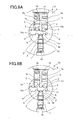
- the turning angle of the tumbler pin 2 is univocally determined by the state of the unlocking code forming recesses 3. If the unlocking code forming recesses 3 are genuine, the cylindrical curvature face 2a at the upper end of the tumbler pins 2 are completely identical to the turning boundary between the plug 1 and the cylinder case 8, as shown in Fig. 9A, so that the plug 1 can be turned.
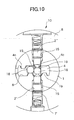
- This floating ball 18 is pushed onto a support projection 19 by one auxiliary tumbler pin 2' in the plug 1, as shown in Fig. 10.
- a higher urging force than that to the other auxiliary tumbler pin 2" arranged to confront the auxiliary tumbler pin 2' is applied to the drive pin 7' on the side of the auxiliary tumbler pin 2'.
- the boundary between the auxiliary tumbler pin 2' and the corresponding drive pin 7' becomes identical to the turning boundary of the plug 1.
- the drive pin 7' corresponding to one auxiliary tumbler pin 2' proceeds into the plug 1 so that the locked state is established. If the holding positions of the two auxiliary tumbler pins 2' and 2" of the floating balls 18 are formed in the unlocking key 4, on the other hand, the boundary between the floating ball 18 and the other auxiliary tumbler pin 2" takes a position popped out of the guide groove 4c, as shown in Fig. 10, so that the unlocking key 4 cannot be inserted into the tumbler insertion holes 15.
- Fig. 11 shows another embodiment of the invention.
- the locking portion 9 is constituted to include the tumbler pins 2 and a side bar 12.
- the upper ends of the tumbler pins 2 and the leading ends of the drive pins 7 are formed like the auxiliary tumbler pins 2' into the frustum-conical shape.
- the tumbler pins 2 are provided at their lower ends with the drive portions 5 and in their side walls with relief grooves 20 over a predetermined length.
- the numeral 12 designates the side bar, which is so moved perpendicularly of the moving direction center axis 11 as to go into and out of the tumbler insertion hole 15.
- the cylinder case 8 is provided with a stopper groove 21, which confronts the side bar 12 when the plug is at the turned locking position.
- the boundary between the tumbler pins 2 and the drive pins 7 urged toward the center by the compression springs 16 do not coincide with the turning boundary of the plug 1 so that the locked state is kept.
- the depth of the unlocking code forming recesses 3 is genuine so that the boundary between the tumbler pins 2 and the drive pins 7 coincides with the turning boundary of the plug 1, the relief groove 20 does not confront the side bar 12 so that the side bar 12 cannot retract into the plug 1.
- the turning boundary between the plug 1 and the cylinder case 8 is not released but kept in the locked state.
Landscapes
- Lock And Its Accessories (AREA)
Applications Claiming Priority (2)
| Application Number | Priority Date | Filing Date | Title |
|---|---|---|---|
| JP2004254917A JP4557643B2 (ja) | 2004-09-01 | 2004-09-01 | シリンダ錠装置 |
| JP2004254916A JP4522198B2 (ja) | 2004-09-01 | 2004-09-01 | シリンダ錠 |
Publications (2)
| Publication Number | Publication Date |
|---|---|
| EP1635012A2 true EP1635012A2 (de) | 2006-03-15 |
| EP1635012A3 EP1635012A3 (de) | 2009-06-17 |
Family
ID=35583416
Family Applications (1)
| Application Number | Title | Priority Date | Filing Date |
|---|---|---|---|
| EP20050018596 Withdrawn EP1635012A3 (de) | 2004-09-01 | 2005-08-26 | Zylinderschloss |
Country Status (2)
| Country | Link |
|---|---|
| US (1) | US7421869B2 (de) |
| EP (1) | EP1635012A3 (de) |
Cited By (5)
| Publication number | Priority date | Publication date | Assignee | Title |
|---|---|---|---|---|
| GB2434827A (en) * | 2006-02-02 | 2007-08-08 | Evva Werke | Cylinder lock including pins with differently arranged probing extensions |
| EP2090726A3 (de) * | 2008-02-05 | 2011-11-02 | Talleres De Escoriaza, S.A. | Schloss mit nicht kreisförmigen und exzentrischen Zuhaltungsstiften, die durch Drehung positioniert werden kann, und Schlüssel mit Kombinationskerben, die mit betrügerischer Absicht schwer nachbildbar sind |
| ES2368543A1 (es) * | 2008-12-11 | 2011-11-18 | Talleres De Escoriaza, S.A. | Llave de cerradura con huellas de combinación de difícil reproducción fraudulenta. |
| US8448485B1 (en) | 2012-03-22 | 2013-05-28 | Winloc Ag | Lock and key combination with rotatable locking tumblers |
| WO2013152597A1 (zh) * | 2012-04-11 | 2013-10-17 | Wei Kongming | 防盗旋转弹子锁锁体及钥匙 |
Families Citing this family (11)
| Publication number | Priority date | Publication date | Assignee | Title |
|---|---|---|---|---|
| RU2007136098A (ru) * | 2005-03-01 | 2009-04-10 | Хамафтеах Хамистовев Лтд. (Il) | Улучшенное запирающее устройство |
| ES2300165B1 (es) * | 2005-09-06 | 2009-05-12 | Talleres De Escoriaza, S.A. | Sistema de llave y cerradura de seguridad frente a su reproduccion fraudulenta. |
| IL186219A0 (en) * | 2007-09-24 | 2008-01-20 | Beer Metal Ind Ltd J | Pin tumbler cylinder lock |
| US20090107195A1 (en) * | 2007-10-30 | 2009-04-30 | Gallian Steven W | Accessory for existing locks to prevent bump lock picking |
| DE102008045739B4 (de) * | 2008-09-04 | 2021-12-30 | ABUS August Bremicker Söhne Kommanditgesellschaft | Schließzylindersystem |
| DE102009044207B4 (de) * | 2009-10-08 | 2012-01-05 | C.Ed. Schulte Gesellschaft mit beschränkter Haftung Zylinderschlossfabrik | Schließzylinder mit zugehörigem Schlüssel und Sperrrippenabtastung |
| US8156777B1 (en) * | 2010-09-23 | 2012-04-17 | Winloc Ag | Lock and key with double code pattern |
| IL211697A (en) * | 2011-03-13 | 2015-02-26 | Mul T Lock Technologies Ltd | A locking element with a moving element |
| US20130061643A1 (en) * | 2011-09-13 | 2013-03-14 | Federal Lock Co., Ltd. | Key |
| US9376837B2 (en) * | 2014-11-11 | 2016-06-28 | Neil D. Koelker | Multisided key and lock |
| CN106193810A (zh) * | 2016-08-31 | 2016-12-07 | 陈相贵 | 一种锁具 |
Family Cites Families (25)
| Publication number | Priority date | Publication date | Assignee | Title |
|---|---|---|---|---|
| US3722240A (en) * | 1971-01-25 | 1973-03-27 | R C Spain | Cylinder lock |
| CA1026118A (en) * | 1975-03-05 | 1978-02-14 | Walter E. Surko (Jr.) | Pin tumbler lock |
| US4098103A (en) * | 1977-03-07 | 1978-07-04 | Walter Kidde & Company, Inc. | Cylinder lock |
| US4208894A (en) * | 1978-09-01 | 1980-06-24 | Emhart Industries, Inc. | Cam lock |
| US4635455A (en) | 1985-07-19 | 1987-01-13 | Medeco Security Locks, Inc. | Cylinder lock |
| US4998426A (en) * | 1987-06-08 | 1991-03-12 | Genakis Joseph M | Cylinder lock |
| IL90211A (en) * | 1989-05-05 | 1991-11-21 | Mul T Lock Ltd | Cylinder lock |
| DE4000179A1 (de) * | 1990-01-05 | 1991-07-11 | Bks Gmbh | Schluessel fuer schliesszylinder, insbesondere von schliessanlagen |
| US5289709A (en) * | 1991-10-24 | 1994-03-01 | Medeco Security Locks, Inc. | Pin tumblers and corresponding keys for cylinder locks |
| US5419168A (en) * | 1991-10-24 | 1995-05-30 | Medeco Security Locks, Inc. | Hierarchical cylinder lock and key system |
| ES2058000B1 (es) * | 1991-12-18 | 1996-09-01 | Recio Alberto Rey | Sistema mecanico de bloqueo para bombillos de cerraduras y similares. |
| FR2704893B1 (fr) * | 1993-05-05 | 1995-08-11 | Tesa | Serrure de sûreté et clé plate pour une telle serrure. |
| SE505364C2 (sv) * | 1993-12-30 | 1997-08-11 | Bo Widen | Cylinderlås-nyckelkombination, nyckel, nyckelämne och lås |
| IT1268686B1 (it) * | 1994-12-27 | 1997-03-06 | Silca Spa | Unita' di chiave e serratura a cilindro |
| US5682779A (en) * | 1995-03-06 | 1997-11-04 | Dolev; Moshe | Mechanically changeable cylinder lock and key with rotating pins |
| US5943890A (en) * | 1996-10-31 | 1999-08-31 | Medeco Security Locks, Inc. | Cylinder lock and key assembly and hierarchical system therefor |
| ITTO980491A1 (it) * | 1998-06-05 | 1999-12-05 | Mottura Serrature Di Sicurezza | Serratura a cilindro. |
| IT1303962B1 (it) * | 1998-10-15 | 2001-03-01 | Italiana Serrature Affini | Serratura a cilindro con dispositivo antieffrazione . |
| US6257033B1 (en) * | 1999-03-08 | 2001-07-10 | Moshe Dolev | Cylinder lock with rotatable pins |
| AU6411200A (en) * | 2000-04-11 | 2001-10-18 | Kaba Schliesssysteme Ag | Safety turning-key |
| US6519988B1 (en) * | 2001-08-24 | 2003-02-18 | One Lus International Co., Ltd. | Structure of a lockset |
| US7086259B2 (en) * | 2002-06-20 | 2006-08-08 | Mul-T-Lock Technologies, Ltd. | Pick resistant lock |
| JP3789419B2 (ja) | 2002-11-05 | 2006-06-21 | 株式会社アルファ | シリンダ錠 |
| US7159424B2 (en) * | 2003-09-22 | 2007-01-09 | Winloc Ag | Lock and key system with extra code combinations |
| SE528815C2 (sv) * | 2005-03-18 | 2007-02-20 | Winloc Ag | Lås- och nyckelsystem med extra kodkombinationer |
-
2005
- 2005-08-26 EP EP20050018596 patent/EP1635012A3/de not_active Withdrawn
- 2005-08-31 US US11/215,072 patent/US7421869B2/en not_active Expired - Fee Related
Cited By (8)
| Publication number | Priority date | Publication date | Assignee | Title |
|---|---|---|---|---|
| GB2434827A (en) * | 2006-02-02 | 2007-08-08 | Evva Werke | Cylinder lock including pins with differently arranged probing extensions |
| AU2007200425B2 (en) * | 2006-02-02 | 2011-07-14 | Evva-Werk Spezialerzeugung Von Zylinder- Und Sicherheitsschlossern Gesellschaft M.B.H & Co. Kommanditgesellschaft | Cylinder lock as well as flat key |
| GB2434827B (en) * | 2006-02-02 | 2011-10-12 | Evva Werke | Cylinder lock as well as flat key |
| EP2090726A3 (de) * | 2008-02-05 | 2011-11-02 | Talleres De Escoriaza, S.A. | Schloss mit nicht kreisförmigen und exzentrischen Zuhaltungsstiften, die durch Drehung positioniert werden kann, und Schlüssel mit Kombinationskerben, die mit betrügerischer Absicht schwer nachbildbar sind |
| EP2511455A1 (de) * | 2008-02-05 | 2012-10-17 | Talleres De Escoriaza, S.A. | Schloss mit Verbindungsstiften mit einem nicht kreisförmigen Querschnitt und Exzentrizität, das in Drehung positioniert werden kann, und Schlossschlüssel mit Verbindungskerben, der schwer mit betrügerischer Absicht nachgebildet werden kann |
| ES2368543A1 (es) * | 2008-12-11 | 2011-11-18 | Talleres De Escoriaza, S.A. | Llave de cerradura con huellas de combinación de difícil reproducción fraudulenta. |
| US8448485B1 (en) | 2012-03-22 | 2013-05-28 | Winloc Ag | Lock and key combination with rotatable locking tumblers |
| WO2013152597A1 (zh) * | 2012-04-11 | 2013-10-17 | Wei Kongming | 防盗旋转弹子锁锁体及钥匙 |
Also Published As
| Publication number | Publication date |
|---|---|
| US20060042335A1 (en) | 2006-03-02 |
| US7421869B2 (en) | 2008-09-09 |
| EP1635012A3 (de) | 2009-06-17 |
Similar Documents
| Publication | Publication Date | Title |
|---|---|---|
| EP1635012A2 (de) | Zylinderschloss | |
| US6945082B2 (en) | Key blank, key and master keying system | |
| CN101142366B (zh) | 具有超额组合的锁和钥匙的系统 | |
| EA008066B1 (ru) | Система замка и ключа с дополнительными кодовыми комбинациями | |
| KR101595106B1 (ko) | 실린더 자물쇠 및 보조 잠금 메카니즘 | |
| US7207200B2 (en) | Key with compound actuator ramps in recessed longitudinal channel | |
| US7958760B2 (en) | Lock and key system with improved tumblers in the lock | |
| JPH0252070B2 (de) | ||
| CN108779652A (zh) | 圆柱锁和钥匙系统 | |
| US12037811B2 (en) | Pick-resistant pin tumbler lock assembly | |
| US6925844B2 (en) | Lock having a helical keyway and accompanying key and methods therefor | |
| WO1998003754A1 (en) | Lock system with key trapping | |
| ES2970212T3 (es) | Llave, sistema de cierre, cilindro de cierre y procedimiento de fabricación | |
| US4221121A (en) | Multi-level lock system and method | |
| GB2108574A (en) | Pick-proof cylinder locks | |
| JP3432433B2 (ja) | シリンダ錠およびこのシリンダ錠に使用する施解錠キー | |
| JP3789419B2 (ja) | シリンダ錠 | |
| JP4557643B2 (ja) | シリンダ錠装置 | |
| JP4522198B2 (ja) | シリンダ錠 | |
| ES2363003T3 (es) | Un sistema de candado y llave con combinaciones extra de códigos. | |
| JP4499651B2 (ja) | シリンダ錠 | |
| ES2971266T3 (es) | Dispositivo de cierre | |
| KR20010033135A (ko) | 개량형 실린더 자물쇠 시스템 | |
| JP2003056222A (ja) | シリンダ錠 | |
| JP2002213120A (ja) | 棒状鍵 |
Legal Events
| Date | Code | Title | Description |
|---|---|---|---|
| PUAI | Public reference made under article 153(3) epc to a published international application that has entered the european phase |
Free format text: ORIGINAL CODE: 0009012 |
|
| AK | Designated contracting states |
Kind code of ref document: A2 Designated state(s): AT BE BG CH CY CZ DE DK EE ES FI FR GB GR HU IE IS IT LI LT LU LV MC NL PL PT RO SE SI SK TR |
|
| AX | Request for extension of the european patent |
Extension state: AL BA HR MK YU |
|
| PUAL | Search report despatched |
Free format text: ORIGINAL CODE: 0009013 |
|
| AK | Designated contracting states |
Kind code of ref document: A3 Designated state(s): AT BE BG CH CY CZ DE DK EE ES FI FR GB GR HU IE IS IT LI LT LU LV MC NL PL PT RO SE SI SK TR |
|
| AX | Request for extension of the european patent |
Extension state: AL BA HR MK YU |
|
| AKX | Designation fees paid | ||
| STAA | Information on the status of an ep patent application or granted ep patent |
Free format text: STATUS: THE APPLICATION IS DEEMED TO BE WITHDRAWN |
|
| 18D | Application deemed to be withdrawn |
Effective date: 20091218 |
|
| REG | Reference to a national code |
Ref country code: DE Ref legal event code: 8566 |