EP1635066B1 - Installation d'alimentation en gaz et procédé d'utilisation associé pour une turbine à gaz - Google Patents
Installation d'alimentation en gaz et procédé d'utilisation associé pour une turbine à gaz Download PDFInfo
- Publication number
- EP1635066B1 EP1635066B1 EP05107639.6A EP05107639A EP1635066B1 EP 1635066 B1 EP1635066 B1 EP 1635066B1 EP 05107639 A EP05107639 A EP 05107639A EP 1635066 B1 EP1635066 B1 EP 1635066B1
- Authority
- EP
- European Patent Office
- Prior art keywords
- compressor
- pressure
- 2soll
- pipeline
- consumer
- Prior art date
- Legal status (The legal status is an assumption and is not a legal conclusion. Google has not performed a legal analysis and makes no representation as to the accuracy of the status listed.)
- Expired - Lifetime
Links
Images
Classifications
-
- F—MECHANICAL ENGINEERING; LIGHTING; HEATING; WEAPONS; BLASTING
- F02—COMBUSTION ENGINES; HOT-GAS OR COMBUSTION-PRODUCT ENGINE PLANTS
- F02C—GAS-TURBINE PLANTS; AIR INTAKES FOR JET-PROPULSION PLANTS; CONTROLLING FUEL SUPPLY IN AIR-BREATHING JET-PROPULSION PLANTS
- F02C7/00—Features, components parts, details or accessories, not provided for in, or of interest apart form groups F02C1/00 - F02C6/00; Air intakes for jet-propulsion plants
- F02C7/22—Fuel supply systems
- F02C7/224—Heating fuel before feeding to the burner
-
- F—MECHANICAL ENGINEERING; LIGHTING; HEATING; WEAPONS; BLASTING
- F02—COMBUSTION ENGINES; HOT-GAS OR COMBUSTION-PRODUCT ENGINE PLANTS
- F02C—GAS-TURBINE PLANTS; AIR INTAKES FOR JET-PROPULSION PLANTS; CONTROLLING FUEL SUPPLY IN AIR-BREATHING JET-PROPULSION PLANTS
- F02C7/00—Features, components parts, details or accessories, not provided for in, or of interest apart form groups F02C1/00 - F02C6/00; Air intakes for jet-propulsion plants
- F02C7/22—Fuel supply systems
-
- F—MECHANICAL ENGINEERING; LIGHTING; HEATING; WEAPONS; BLASTING
- F04—POSITIVE - DISPLACEMENT MACHINES FOR LIQUIDS; PUMPS FOR LIQUIDS OR ELASTIC FLUIDS
- F04D—NON-POSITIVE-DISPLACEMENT PUMPS
- F04D27/00—Control, e.g. regulation, of pumps, pumping installations or pumping systems specially adapted for elastic fluids
- F04D27/02—Surge control
- F04D27/0284—Conjoint control of two or more different functions
-
- F—MECHANICAL ENGINEERING; LIGHTING; HEATING; WEAPONS; BLASTING
- F05—INDEXING SCHEMES RELATING TO ENGINES OR PUMPS IN VARIOUS SUBCLASSES OF CLASSES F01-F04
- F05D—INDEXING SCHEME FOR ASPECTS RELATING TO NON-POSITIVE-DISPLACEMENT MACHINES OR ENGINES, GAS-TURBINES OR JET-PROPULSION PLANTS
- F05D2270/00—Control
- F05D2270/30—Control parameters, e.g. input parameters
- F05D2270/301—Pressure
-
- Y—GENERAL TAGGING OF NEW TECHNOLOGICAL DEVELOPMENTS; GENERAL TAGGING OF CROSS-SECTIONAL TECHNOLOGIES SPANNING OVER SEVERAL SECTIONS OF THE IPC; TECHNICAL SUBJECTS COVERED BY FORMER USPC CROSS-REFERENCE ART COLLECTIONS [XRACs] AND DIGESTS
- Y10—TECHNICAL SUBJECTS COVERED BY FORMER USPC
- Y10T—TECHNICAL SUBJECTS COVERED BY FORMER US CLASSIFICATION
- Y10T137/00—Fluid handling
- Y10T137/0318—Processes
- Y10T137/0324—With control of flow by a condition or characteristic of a fluid
- Y10T137/0329—Mixing of plural fluids of diverse characteristics or conditions
- Y10T137/0346—Controlled by heat of combustion of mixture
Definitions
- the present invention relates to a method for operating a gas supply system for a gas turbine with the features of the preamble of claim 1.
- the present invention also relates to a gas supply system for a gas turbine, having the features of the preamble of claim 7.
- the known gas supply system comprises a gas-conducting pipeline, a pipeline-mounted, controllable compressor and a pipeline connected to the compressor, downstream of the compressor, namely a gas turbine.
- a control device in the form of a regulator is provided, which regulates the compressor in dependence on a desired-actual comparison of a compressor outlet pressure.
- the controller can change the speed and / or the vane position of the compressor.
- the Compressor outlet pressure can be measured in the conventional manner at the compressor outlet.
- the compressor outlet nominal pressure is usually fixed, this preset value depending on the respective location of the gas turbine, in particular on the expected lowest ambient temperatures.
- the predetermined Kompressorauslasssolldruck results from the maximum gas turbine power and the maximum gas temperature and from the lower heating value of the gas.
- a throttle body is arranged in the pipeline, which is actuated by means of a separate regulator.
- a pressure change in the pipeline can be adjusted using the throttle body always a desired compressor inlet pressure, which allows the compressor to set the compressor discharge target pressure.
- the compressor can always be operated with high power, in particular with its rated power.
- this is not always useful for energetic reasons.
- compressors with a fixed compression ratio are used regularly here. If the pressure in the pipeline increases, the discharge pressure can reach inadmissibly high values unless the inlet pressure is regulated accordingly with the aid of the upstream throttle body. Such a compressor works permanently at full load or nominal load.
- From the DE 15 03 568 A1 is a compressor station for gaseous media, which serve to compensate for the pressure drop in the line to maintain a final pressure at the consumer known.
- the DE 103 41 758 A1 describes a gas compressor controller and a gas turbine engine control mechanism that can control a constant gas compressor discharge pressure to suppress a pressure increase of a fuel gas supplied to a gas turbine even if a load rejection or a load loss occurs.
- the present invention deals with the problem for a gas supply system of the above mentioned type to provide an improved embodiment and an improved operating method, whereby in particular a reduced energy consumption of the compressor is achieved.
- the present invention is based on the general idea to regulate the compressor in response to the consumer inlet pressure.
- the compressor can be operated directly depending on the actual needs, which makes it possible to reduce the power of the compressor according to a reduced pressure requirement. This can reduce the energy consumption of the compressor.
- the invention thus provides a feedback of the current power requirement of the gas turbine to the upstream gas supply system.
- the required consumer entry pressure is determined as a function of at least one current consumer parameter, e.g. its load state, and / or at least one current environmental parameter, such as the ambient temperature, determined.
- the required consumer inlet target pressure can be determined independently of the consumer or independently of an active feedback from the consumer.
- the gas supply system can work autonomously.
- the compressor discharge target pressure (p 2SOLL ) is determined as a function of a pressure drop which occurs in the pipeline between a compressor outlet and a consumer inlet.
- this Druckabsenk listening is required only if the pipeline pressure, that is, the compressor inlet pressure measured upstream of the pressure lowering device is greater than the determined compressor outlet nominal pressure. In this case, the excessively high pipeline pressure is throttled to the required compressor discharge nominal pressure with the aid of the pressure lowering device. At the same time, the compressor is deactivated so that it does not absorb any energy. In contrast, with smaller pipeline pressures the DruckabsenkINA is deactivated and generated by means of the compressor, the required pressure increase.
- bypasses may be provided which internally, so within the Druckabsenk recognized or within the compressor, or outside, ie by separate bypass lines, which extend in particular outside the compressor or the Druckabsenk sensible, may be formed ,
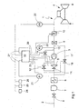
- FIG. 1 shows a greatly simplified, schematics-like schematic diagram of a gas supply system according to the invention.
- a gas supply system 1 comprises a pipeline 2, in which a compressor 3 is arranged and which is connected to a consumer 4.
- the consumer 4 is connected downstream of the compressor 3.
- the consumer 4 is a gas turbine, in particular for power generation in a power plant.
- a Druckabsenk Nurn 5 is connected upstream, by means of which in the pressure lowering device 5 by the gas flowing through the pressure can be selectively lowered.
- a dew-point heating device 6 is arranged, with the aid of which, at low ambient temperatures, the gas can be heated above the dew point of, if appropriate, entrained liquid.
- a separator 7 for separating particles and / or droplets carried by the gas flow.
- a check valve 8 is arranged, with the aid thereof, e.g. In case of emergency, the gas supply can be switched off completely.
- a fine filter 9 Downstream of the compressor 3, a fine filter 9 is arranged, with the help of small or fine-grained liquid or solid impurities can be filtered out of the gas flow. Downstream of this fine filter 9, a preheating device 10 is arranged, with the aid of which the gas flow can be heated to a predetermined temperature, if necessary.
- a first bypass 11 is also provided, which serves for bypassing or for low-resistance flow through the Druckabsenk issued 5.
- the first bypass 11 may be formed internally, that is, in the interior of the pressure lowering device 5.
- the first bypass 11 - as shown here - be formed by a separate bypass line.
- the first bypass 11 can be controlled, which is indicated here by a first control valve 12.
- this first control valve 12 can basically be dispensed with, since its function can be realized by a control or by actuators of the pressure lowering device 5.
- a second bypass 13 which serves for bypassing or for low-resistance flow through the compressor 3 and is also controllable.
- the second bypass 13 may be implemented internally, that is integrally in the compressor 3 or externally by a separate bypass line.
- the second bypass 13 is also directly or indirectly controllable via the compressor 3, which is indicated here by a second control valve 14.
- a third bypass 17 is provided which bypasses both the Druckabsenk Anlagen 5 and the compressor 3, externally, so with a separate bypass line is realized and with the aid of a third control valve 18 is controllable.
- This third bypass 17 is basically internally feasible.
- the gas supply system 1 is equipped with a control device 19 which controls the controllable or controllable components of the gas supply system 1 via a plurality of control lines 20, ie here the compressor 3, the pressure lowering device 5, the preheating device 10 and the three bypasses 11, 13, 17 and the control valves 12, 14, 18th
- the gas supply system 1 has a plurality of sensors, namely a first pressure sensor 21 for determining a compressor inlet pressure p 1IST , a second pressure sensor 22 for determining a compressor outlet pressure p 2IST, a third pressure sensor 23 for determining a consumer inlet pressure p 3IST and other sensors 24, 25, 26 for determining at least one environmental parameter, such as ambient temperature, ambient pressure and humidity.
- the aforementioned sensors 21 to 26 are connected via corresponding signal lines 27 to the control device 19. In this way, the control device 19 can take into account the values detected by the sensors 21 to 26 for the control or regulation of the components connected thereto.
- Fig. 1 is the Druckabsenk worn 5 configured with respect to the compressor 3 as a separate component.
- the pressure lowering device 5 is integrated physically or functionally into the compressor 3 is preferred.
- Such integration can be functionally particularly easy to implement in a controllable compressor 3, for example by means of adjustable vanes eg at the inlet of the compressor 3. It is clear that in such an embodiment, in principle, only the third bypass 17 is required.
- two different operating states are generally distinguished from each other: First, the operation of the gas supply system 1 at a Kompressoreintrittist founded p 1IST , which is smaller than a required Kompressoraustrittsoll Kunststoff p 2SOLL , so p 1IST ⁇ p 2SOLL , and on the other an operation at a Kompressoreintrittist founded p 1IST , which is greater than the desired desired compressor discharge p 2SOLL , so p 1IST > p 2SOLL.
- the state where the compressor inlet pressure p 1IST is equal to the desired desired compressor discharge pressure p 2SOLL may be conveniently assigned to one or the other of the two operating conditions described above or, alternatively, to another operating state.
- a special feature here is that the compressor inlet pressure p 1 upstream of the compressor 3 associated Druckabsenk Nur 5 is measured, so not directly at the compressor inlet.
- the control device 19 now controls the compressor 3 as a function of a desired-actual comparison for the compressor outlet pressure p 2 .
- the compressor discharge target pressure p 2SOLL is determined as a function of the consumption entry target pressure p 3SOLL .
- This consumer entry target pressure p 3SOLL can be supplied , for example, from a controller (not shown here) of the consumer 4 to the control device 19.
- the gas supply system 1 determines the consumer input target pressure p 3SOLL essentially autonomously.
- the consumer input target pressure p 3SOLL is determined as a function of at least one consumer parameter , such as the current power requirement to the consumer, and / or at least one environmental parameter , for example the ambient temperature and / or the ambient pressure and / or the ambient humidity.
- the controller 19 from the at least one environmental parameters and from the at least one consumer parameters determine the required Seaereintrittsolldruck p 3SOLL that must be present so that the consumer 4 can reach a predetermined operating condition, suitably the nominal operating condition.
- the compressor outlet target pressure P 2SOLL is also determined as a function of the pressure drop which occurs during operation of the gas supply system 1 between compressor outlet and consumption inlet.
- the controller 19 activates the first bypass 11 and the compressor 3.
- the depressurizer 5, the second bypass 13, and the preheater 10 are then deactivated. This means that at a pressure in the pipeline 2, which is smaller than the compressor discharge target pressure p 2SOLL upstream of the compressor 3 substantially no throttling takes place. Likewise, downstream of the compressor 3 throttling to the consumer 4 is avoided as possible in order to minimize the total energy consumption of the compressor 3.
- the external first bypass 11 and / or the external second bypass 13 may be omitted; as well can then basically on the Pressure lowering device 5 can be omitted.
- the third bypass 17 may be sufficient.
- the control device 19 actuates the components of the gas supply system 1 so that now the first bypass 11 is deactivated, the pressure lowering device 5 is activated, the compressor 3 is deactivated, the second bypass 13 activated and optionally the preheater 10 is activated. In this operating state can be completely dispensed with the operation of the compressor 3, so that this then consumes no energy.
- the supply system 1 thus enables a reduced energy consumption, which benefits the overall efficiency of the power plant.
- the third bypass 17 may also be activated for special operating conditions, for example, in the event that the compressor inlet pressure p 1IST is equal to the compressor discharge target pressure p 2SOLL .
- This "special operating state" should in itself form the desired ideal or nominal state, since then neither throttling nor compression of the gas is required.
Landscapes
- Engineering & Computer Science (AREA)
- Chemical & Material Sciences (AREA)
- Combustion & Propulsion (AREA)
- Mechanical Engineering (AREA)
- General Engineering & Computer Science (AREA)
- Control Of Positive-Displacement Air Blowers (AREA)
- Pipeline Systems (AREA)
Claims (12)
- Procédé pour faire fonctionner une installation d'alimentation en gaz (1) pour une turbine à gaz comprenant une canalisation (2) acheminant du gaz, un compresseur (3) réglable disposé dans la canalisation (2) et au moins un consommateur, à savoir une turbine à gaz (4), raccordé à la canalisation (2) et placé en aval du compresseur (3), le compresseur (3) étant réglé en fonction d'une comparaison d'une pression de consigne de sortie de compresseur (p2SOLL) avec une pression réelle de sortie de compresseur (p2IST), la pression de consigne de sortie de compresseur (p2SOLL) étant déterminée en fonction d'une pression de consigne d'entrée de consommateur (p3SOLL) et la pression de consigne d'entrée de consommateur (p3SOLL) étant déterminée en fonction d'au moins un paramètre de consommateur et/ou d'au moins un paramètre d'environnement,
caractérisé en ce que
la pression de consigne de sortie de compresseur (p2SOLL) est en outre déterminée en fonction d'une réduction de pression qui se présente dans la canalisation (2) entre une sortie de compresseur et une entrée de consommateur. - Procédé selon la revendication 1,
caractérisé en ce que
le compresseur (3) est réglé en termes de sa puissance débitée. - Procédé selon l'une quelconque des revendications 1 et 2,
caractérisé en ce
qu'un dispositif de diminution de pression (5) est prévu, lequel est soit placé en amont du compresseur (3) et disposé dans la canalisation (2), soit intégré dans le compresseur (3) au moins en termes de sa fonction de diminution de pression. - Procédé selon la revendication 3,
caractérisé en ce que- la pression d'entrée de compresseur (p1) est mesurée en amont du dispositif de diminution de pression (5),- dans le cas d'une pression réelle d'entrée de compresseur (p1IST) qui est inférieure à la pression de consigne de sortie de compresseur (p2SOLL), le dispositif de diminution de pression (5) est déconnecté et le compresseur (3) est connecté,- dans le cas d'une pression réelle d'entrée de compresseur (p1IST) qui est supérieure à la pression de consigne de sortie de compresseur (p2SOLL), le dispositif de diminution de pression (5) est connecté et le compresseur (3) est déconnecté. - Procédé selon la revendication 4,
caractérisé en ce
qu'une dérivation interne ou externe (17) pouvant être commandée et contournant le compresseur (3) et le dispositif de diminution de pression (5) est prévue, à travers laquelle le gaz est guidé lorsque la pression réelle d'entrée de compresseur (p1IST) est égale à la pression de consigne de sortie de compresseur (p2SOLL). - Procédé selon la revendication 4 ou 5,
caractérisé en ce que- un dispositif de préchauffage (10) placé en aval du compresseur (3) et placé en amont de la turbine à gaz (4) est disposé dans la canalisation (2),- dans le cas d'une pression réelle d'entrée de compresseur (p1IST) qui est supérieure à la pression de consigne de sortie de compresseur (p2SOLL), le dispositif de préchauffage (10) est connecté,- dans le cas d'une pression réelle d'entrée de compresseur (p1IST) qui est inférieure à la pression de consigne de sortie de compresseur (p2SOLL), le dispositif de préchauffage (10) est déconnecté. - Installation d'alimentation en gaz pour une turbine à gaz comprenant une canalisation (2) acheminant du gaz, un compresseur (3) pouvant être réglé par un dispositif de commande (19) et disposé dans la canalisation (2) et au moins un consommateur, à savoir une turbine à gaz (4), placé en aval du compresseur (3), le dispositif de commande (19) étant configuré pour le réglage du compresseur (3) en fonction d'une comparaison valeur de consigne-valeur réelle de la pression de sortie de compresseur (p2),
le dispositif de commande (19) étant configuré pour la détermination de la pression de consigne de sortie de compresseur (p2SOLL) en fonction d'une pression de consigne d'entrée de consommateur (p3SOLL) et le dispositif de commande (19) étant configuré pour la détermination de la pression de consigne d'entrée de consommateur (p3SOLL) en fonction d'au moins un paramètre de consommateur et/ou d'au moins un paramètre d'environnement, caractérisée en ce que- le dispositif de commande (19) est configuré pour la détermination de la pression de consigne de sortie de compresseur (p2SOLL) en fonction d'une réduction de pression qui se présente lors du fonctionnement dans la canalisation (2) entre une sortie de compresseur et une entrée de consommateur. - Installation d'alimentation en gaz selon la revendication 7,
caractérisée en ce que
le dispositif de commande (19) est configuré pour le réglage de la puissance débitée du compresseur (3). - Installation d'alimentation en gaz selon l'une quelconque des revendications 7 et 8,
caractérisée en ce
qu'un dispositif de diminution de pression réglable (5) est prévu, lequel est soit placé en amont du compresseur (3) et disposé dans la canalisation (2), soit intégré dans le compresseur (3) au moins en termes de sa fonction de diminution de pression. - Installation d'alimentation en gaz selon la revendication 9,
caractérisée en ce que- la mesure de pression réelle d'entrée de compresseur (p1IST) est située en amont du dispositif de diminution de pression (5),- le dispositif de commande (19) est configuré de telle sorte que, lors du fonctionnement, dans le cas d'une pression réelle d'entrée de compresseur (p1IST) qui est inférieure à la pression de consigne de sortie de compresseur (p2SOLL), le dispositif de diminution de pression (5) est déconnecté et le compresseur (3) est connecté et fonctionne de manière réglée,- le dispositif de commande (19) est configuré de telle sorte que, lors du fonctionnement, dans le cas d'une pression réelle d'entrée de compresseur (p1IST) qui est supérieure à la pression de consigne de sortie de compresseur (p2SOLL), le dispositif de diminution de pression (5) est connecté et fonctionne de manière réglée et le compresseur (3) est déconnecté. - Installation d'alimentation en gaz selon la revendication 10,
caractérisée en ce
qu'une dérivation interne ou externe (17) pouvant être commandée et contournant le compresseur (3) et le dispositif de diminution de pression (5) est prévue, et le dispositif de commande (19) est configuré de telle sorte qu'il guide le gaz à travers la dérivation interne ou externe (17) lors du fonctionnement lorsque la pression réelle d'entrée de compresseur (p1IST) est égale à la pression de consigne de sortie de compresseur (P2SOLL). - Installation d'alimentation en gaz selon la revendication 10 ou 11,
caractérisée en ce que- un dispositif de préchauffage réglable (10) placé en aval du compresseur (3) et placé en amont de la turbine à gaz (4) est disposé dans la canalisation (2),- le dispositif de commande (19) est configuré de telle sorte que, lors du fonctionnement, dans le cas d'une pression réelle d'entrée de compresseur (p1IST) qui est supérieure à la pression de consigne de sortie de compresseur (p2SOLL), il connecte et fait fonctionner de manière réglée le dispositif de préchauffage (10),- le dispositif de commande (19) est configuré de telle sorte que, lors du fonctionnement, dans le cas d'une pression réelle d'entrée de compresseur (p1IST) qui est inférieure à la pression de consigne de sortie de compresseur (p2SOLL), il déconnecte le dispositif de préchauffage (10).
Applications Claiming Priority (1)
| Application Number | Priority Date | Filing Date | Title |
|---|---|---|---|
| CH14862004 | 2004-09-09 |
Publications (3)
| Publication Number | Publication Date |
|---|---|
| EP1635066A2 EP1635066A2 (fr) | 2006-03-15 |
| EP1635066A3 EP1635066A3 (fr) | 2012-10-31 |
| EP1635066B1 true EP1635066B1 (fr) | 2015-06-03 |
Family
ID=34973824
Family Applications (1)
| Application Number | Title | Priority Date | Filing Date |
|---|---|---|---|
| EP05107639.6A Expired - Lifetime EP1635066B1 (fr) | 2004-09-09 | 2005-08-19 | Installation d'alimentation en gaz et procédé d'utilisation associé pour une turbine à gaz |
Country Status (3)
| Country | Link |
|---|---|
| US (1) | US7497668B2 (fr) |
| EP (1) | EP1635066B1 (fr) |
| ES (1) | ES2544745T3 (fr) |
Families Citing this family (7)
| Publication number | Priority date | Publication date | Assignee | Title |
|---|---|---|---|---|
| EP1979615A4 (fr) * | 2006-02-01 | 2011-03-30 | Ingersoll Rand Co | Systeme et procede de controle d'un compresseur a ecoulement d'air |
| CH700991A1 (de) | 2009-05-13 | 2010-11-15 | Alstom Technology Ltd | Verfahren zum betrieb einer gasturbinenanlage mit einer verdichterstation für gasförmigen brennstoff. |
| WO2012013530A1 (fr) * | 2010-07-29 | 2012-02-02 | Siemens Aktiengesellschaft | Procédé pour faire fonctionner un compresseur |
| US9371917B2 (en) * | 2013-04-30 | 2016-06-21 | General Electric Company | Fuel conditioning system |
| GB2523324A (en) * | 2014-02-19 | 2015-08-26 | Combined Cycle Enhancements Ltd | Improved fuel supply system for a gas turbine |
| JP6286580B2 (ja) * | 2014-03-31 | 2018-02-28 | シーメンス アクティエンゲゼルシャフト | ガスタービン設備のガス供給系のための圧力調整装置 |
| JP6623318B1 (ja) * | 2019-05-13 | 2019-12-18 | 三菱日立パワーシステムズ株式会社 | 燃料ガス供給装置および方法 |
Family Cites Families (9)
| Publication number | Priority date | Publication date | Assignee | Title |
|---|---|---|---|---|
| DE1503568A1 (de) * | 1966-03-15 | 1971-01-21 | Kloeckner Humboldt Deutz Ag | Gasturbinenkraftanlage |
| US4273508A (en) * | 1978-12-14 | 1981-06-16 | Fomichev Mikhail M | Method for automatic control of power plant and power plant of compressor station of gas pipeline system, wherein said method is effected |
| US4922710A (en) * | 1989-01-04 | 1990-05-08 | General Electric Company | Integrated boost compressor/gas turbine control |
| US5606858A (en) * | 1993-07-22 | 1997-03-04 | Ormat Industries, Ltd. | Energy recovery, pressure reducing system and method for using the same |
| JP3658415B2 (ja) * | 1993-12-28 | 2005-06-08 | 株式会社 日立インダストリイズ | ガスタービン装置 |
| DE19860639A1 (de) * | 1998-12-29 | 2000-07-06 | Man Turbomasch Ag Ghh Borsig | Verfahren zum Betreiben eines Kompressors mit nachgeschaltetem Verbraucher, und nach dem Verfahren arbeitende Anlage |
| DE10012380A1 (de) * | 2000-03-14 | 2001-09-20 | Man Turbomasch Ag Ghh Borsig | Verfahren zum Schutz eines Turbokompressors vor Betrieb im instabilen Arbeitsbereich |
| US6622489B1 (en) * | 2000-10-25 | 2003-09-23 | Hybrid Power Generation Systems, Llc | Integrated gas booster modulation control method |
| JP3854556B2 (ja) * | 2002-09-11 | 2006-12-06 | 三菱重工業株式会社 | ガスタービンプラント制御機構 |
-
2005
- 2005-08-19 EP EP05107639.6A patent/EP1635066B1/fr not_active Expired - Lifetime
- 2005-08-19 ES ES05107639.6T patent/ES2544745T3/es not_active Expired - Lifetime
- 2005-09-08 US US11/222,422 patent/US7497668B2/en not_active Expired - Fee Related
Also Published As
| Publication number | Publication date |
|---|---|
| US20070012358A1 (en) | 2007-01-18 |
| EP1635066A2 (fr) | 2006-03-15 |
| EP1635066A3 (fr) | 2012-10-31 |
| ES2544745T3 (es) | 2015-09-03 |
| US7497668B2 (en) | 2009-03-03 |
Similar Documents
| Publication | Publication Date | Title |
|---|---|---|
| EP2977596B1 (fr) | Moteur a combustion interne dote d'un dispositif de reglage | |
| EP1016787B1 (fr) | Procédé d' opération d' un compresseur et système fonctionnant selon ce procédé | |
| EP0957314B1 (fr) | Dispositif de commande pour des brûleurs à gaz | |
| WO2015150056A1 (fr) | Dispositif de régulation de pression pour système d'alimentation en gaz d'une turbine à gaz | |
| DE102006034917B4 (de) | Volumenstromregler | |
| EP3994294B1 (fr) | Système soec et procédé de fonctionnement d'un système soec | |
| DE102019216624A1 (de) | Verfahren zum Betreiben eines Brennstoffzellensystems | |
| EP0907052A2 (fr) | Dispositif de commande de rapport pneumatique | |
| DE102019101357B4 (de) | Anordnung zum zweistufigen Lufteinlassen und -auslassen für elektrisch gesteuerte Proportionalventile | |
| EP1635066B1 (fr) | Installation d'alimentation en gaz et procédé d'utilisation associé pour une turbine à gaz | |
| EP1069314A1 (fr) | Commande d'une unité-compresseur | |
| EP2071156B1 (fr) | Système de distribution de carburant d'une turbine à gaz avec ensemble brûleur à plusieurs étages | |
| EP2706424B1 (fr) | Dispositif de régulation de la pression et/ou du débit massique pour un entraînement spatial | |
| DE10340177A1 (de) | Zerstäubungs- und Eindüsensystem, und Verfahren zum Betrieb | |
| DE3811230C2 (fr) | ||
| EP3619066B1 (fr) | Système de régulation de la pression comprenant un ensemble d'étranglement | |
| DE102004007104A1 (de) | Coanda-Strömungsverstärker, Verfahren zum Betreiben eines Coanda-Strömungsverstärkers und mit einem Coanda-Strömungsverstärker ausgestattetes Brennstoffzellensystem | |
| EP2597317A1 (fr) | Machine-outil et groupe moteur-pompe | |
| EP3333405B1 (fr) | Unité de dosage pour un moteur à combustion interne fonctionnant au gaz | |
| EP1739776A1 (fr) | Méthode pour amener des gaz d'opération dans un espace de gaz d'une pile à combustible et une pile à combustible | |
| DE19627759C2 (de) | Brennstoffregler für Turbo-Strahltriebwerke | |
| EP3619062B1 (fr) | Procédé permettant de faire fonctionner un système de régulation de la pression dans un véhicule ainsi que système de régulation de la pression | |
| DE884131C (de) | Gasturbinenanlage mit Einrichtung zur Lastregelung | |
| EP1335259A1 (fr) | Regulateur de pression de gaz | |
| WO2007098880A1 (fr) | Procédé et dispositif pour améliorer le comportement instable de moteurs à gaz à mélange pauvre |
Legal Events
| Date | Code | Title | Description |
|---|---|---|---|
| PUAI | Public reference made under article 153(3) epc to a published international application that has entered the european phase |
Free format text: ORIGINAL CODE: 0009012 |
|
| AK | Designated contracting states |
Kind code of ref document: A2 Designated state(s): AT BE BG CH CY CZ DE DK EE ES FI FR GB GR HU IE IS IT LI LT LU LV MC NL PL PT RO SE SI SK TR |
|
| AX | Request for extension of the european patent |
Extension state: AL BA HR MK YU |
|
| REG | Reference to a national code |
Ref country code: DE Ref legal event code: R079 Ref document number: 502005014809 Country of ref document: DE Free format text: PREVIOUS MAIN CLASS: F04D0027020000 Ipc: F04D0027000000 |
|
| PUAL | Search report despatched |
Free format text: ORIGINAL CODE: 0009013 |
|
| AK | Designated contracting states |
Kind code of ref document: A3 Designated state(s): AT BE BG CH CY CZ DE DK EE ES FI FR GB GR HU IE IS IT LI LT LU LV MC NL PL PT RO SE SI SK TR |
|
| AX | Request for extension of the european patent |
Extension state: AL BA HR MK YU |
|
| RIC1 | Information provided on ipc code assigned before grant |
Ipc: F04D 27/00 20060101AFI20120925BHEP Ipc: F02C 3/22 20060101ALI20120925BHEP Ipc: F02C 7/22 20060101ALI20120925BHEP |
|
| 17P | Request for examination filed |
Effective date: 20130422 |
|
| AKX | Designation fees paid |
Designated state(s): AT BE BG CH CY CZ DE DK EE ES FI FR GB GR HU IE IS IT LI LT LU LV MC NL PL PT RO SE SI SK TR |
|
| 17Q | First examination report despatched |
Effective date: 20130920 |
|
| GRAP | Despatch of communication of intention to grant a patent |
Free format text: ORIGINAL CODE: EPIDOSNIGR1 |
|
| INTG | Intention to grant announced |
Effective date: 20150106 |
|
| GRAS | Grant fee paid |
Free format text: ORIGINAL CODE: EPIDOSNIGR3 |
|
| GRAA | (expected) grant |
Free format text: ORIGINAL CODE: 0009210 |
|
| AK | Designated contracting states |
Kind code of ref document: B1 Designated state(s): AT BE BG CH CY CZ DE DK EE ES FI FR GB GR HU IE IS IT LI LT LU LV MC NL PL PT RO SE SI SK TR |
|
| REG | Reference to a national code |
Ref country code: GB Ref legal event code: FG4D Free format text: NOT ENGLISH |
|
| REG | Reference to a national code |
Ref country code: DE Ref legal event code: R081 Ref document number: 502005014809 Country of ref document: DE Owner name: GENERAL ELECTRIC TECHNOLOGY GMBH, CH Free format text: FORMER OWNER: ALSTOM TECHNOLOGY LTD., BADEN, CH Ref country code: DE Ref legal event code: R081 Ref document number: 502005014809 Country of ref document: DE Owner name: ANSALDO ENERGIA IP UK LIMITED, GB Free format text: FORMER OWNER: ALSTOM TECHNOLOGY LTD., BADEN, CH |
|
| REG | Reference to a national code |
Ref country code: CH Ref legal event code: EP |
|
| REG | Reference to a national code |
Ref country code: IE Ref legal event code: FG4D Free format text: LANGUAGE OF EP DOCUMENT: GERMAN |
|
| REG | Reference to a national code |
Ref country code: AT Ref legal event code: REF Ref document number: 730084 Country of ref document: AT Kind code of ref document: T Effective date: 20150715 |
|
| REG | Reference to a national code |
Ref country code: DE Ref legal event code: R096 Ref document number: 502005014809 Country of ref document: DE |
|
| REG | Reference to a national code |
Ref country code: ES Ref legal event code: FG2A Ref document number: 2544745 Country of ref document: ES Kind code of ref document: T3 Effective date: 20150903 |
|
| PG25 | Lapsed in a contracting state [announced via postgrant information from national office to epo] |
Ref country code: FI Free format text: LAPSE BECAUSE OF FAILURE TO SUBMIT A TRANSLATION OF THE DESCRIPTION OR TO PAY THE FEE WITHIN THE PRESCRIBED TIME-LIMIT Effective date: 20150603 Ref country code: LT Free format text: LAPSE BECAUSE OF FAILURE TO SUBMIT A TRANSLATION OF THE DESCRIPTION OR TO PAY THE FEE WITHIN THE PRESCRIBED TIME-LIMIT Effective date: 20150603 |
|
| REG | Reference to a national code |
Ref country code: NL Ref legal event code: MP Effective date: 20150603 |
|
| REG | Reference to a national code |
Ref country code: LT Ref legal event code: MG4D |
|
| PG25 | Lapsed in a contracting state [announced via postgrant information from national office to epo] |
Ref country code: BG Free format text: LAPSE BECAUSE OF FAILURE TO SUBMIT A TRANSLATION OF THE DESCRIPTION OR TO PAY THE FEE WITHIN THE PRESCRIBED TIME-LIMIT Effective date: 20150903 Ref country code: GR Free format text: LAPSE BECAUSE OF FAILURE TO SUBMIT A TRANSLATION OF THE DESCRIPTION OR TO PAY THE FEE WITHIN THE PRESCRIBED TIME-LIMIT Effective date: 20150904 Ref country code: LV Free format text: LAPSE BECAUSE OF FAILURE TO SUBMIT A TRANSLATION OF THE DESCRIPTION OR TO PAY THE FEE WITHIN THE PRESCRIBED TIME-LIMIT Effective date: 20150603 |
|
| PG25 | Lapsed in a contracting state [announced via postgrant information from national office to epo] |
Ref country code: EE Free format text: LAPSE BECAUSE OF FAILURE TO SUBMIT A TRANSLATION OF THE DESCRIPTION OR TO PAY THE FEE WITHIN THE PRESCRIBED TIME-LIMIT Effective date: 20150603 |
|
| PG25 | Lapsed in a contracting state [announced via postgrant information from national office to epo] |
Ref country code: RO Free format text: LAPSE BECAUSE OF NON-PAYMENT OF DUE FEES Effective date: 20150603 Ref country code: PT Free format text: LAPSE BECAUSE OF FAILURE TO SUBMIT A TRANSLATION OF THE DESCRIPTION OR TO PAY THE FEE WITHIN THE PRESCRIBED TIME-LIMIT Effective date: 20151006 Ref country code: SK Free format text: LAPSE BECAUSE OF FAILURE TO SUBMIT A TRANSLATION OF THE DESCRIPTION OR TO PAY THE FEE WITHIN THE PRESCRIBED TIME-LIMIT Effective date: 20150603 Ref country code: IS Free format text: LAPSE BECAUSE OF FAILURE TO SUBMIT A TRANSLATION OF THE DESCRIPTION OR TO PAY THE FEE WITHIN THE PRESCRIBED TIME-LIMIT Effective date: 20151003 Ref country code: PL Free format text: LAPSE BECAUSE OF FAILURE TO SUBMIT A TRANSLATION OF THE DESCRIPTION OR TO PAY THE FEE WITHIN THE PRESCRIBED TIME-LIMIT Effective date: 20150603 Ref country code: CZ Free format text: LAPSE BECAUSE OF FAILURE TO SUBMIT A TRANSLATION OF THE DESCRIPTION OR TO PAY THE FEE WITHIN THE PRESCRIBED TIME-LIMIT Effective date: 20150603 |
|
| REG | Reference to a national code |
Ref country code: DE Ref legal event code: R097 Ref document number: 502005014809 Country of ref document: DE |
|
| PG25 | Lapsed in a contracting state [announced via postgrant information from national office to epo] |
Ref country code: MC Free format text: LAPSE BECAUSE OF FAILURE TO SUBMIT A TRANSLATION OF THE DESCRIPTION OR TO PAY THE FEE WITHIN THE PRESCRIBED TIME-LIMIT Effective date: 20150603 Ref country code: LU Free format text: LAPSE BECAUSE OF FAILURE TO SUBMIT A TRANSLATION OF THE DESCRIPTION OR TO PAY THE FEE WITHIN THE PRESCRIBED TIME-LIMIT Effective date: 20150819 |
|
| REG | Reference to a national code |
Ref country code: CH Ref legal event code: PL |
|
| PLBE | No opposition filed within time limit |
Free format text: ORIGINAL CODE: 0009261 |
|
| STAA | Information on the status of an ep patent application or granted ep patent |
Free format text: STATUS: NO OPPOSITION FILED WITHIN TIME LIMIT |
|
| PG25 | Lapsed in a contracting state [announced via postgrant information from national office to epo] |
Ref country code: DK Free format text: LAPSE BECAUSE OF FAILURE TO SUBMIT A TRANSLATION OF THE DESCRIPTION OR TO PAY THE FEE WITHIN THE PRESCRIBED TIME-LIMIT Effective date: 20150603 Ref country code: IT Free format text: LAPSE BECAUSE OF FAILURE TO SUBMIT A TRANSLATION OF THE DESCRIPTION OR TO PAY THE FEE WITHIN THE PRESCRIBED TIME-LIMIT Effective date: 20150603 Ref country code: LI Free format text: LAPSE BECAUSE OF NON-PAYMENT OF DUE FEES Effective date: 20150831 Ref country code: CH Free format text: LAPSE BECAUSE OF NON-PAYMENT OF DUE FEES Effective date: 20150831 |
|
| 26N | No opposition filed |
Effective date: 20160304 |
|
| PG25 | Lapsed in a contracting state [announced via postgrant information from national office to epo] |
Ref country code: SI Free format text: LAPSE BECAUSE OF FAILURE TO SUBMIT A TRANSLATION OF THE DESCRIPTION OR TO PAY THE FEE WITHIN THE PRESCRIBED TIME-LIMIT Effective date: 20150603 |
|
| REG | Reference to a national code |
Ref country code: IE Ref legal event code: MM4A |
|
| REG | Reference to a national code |
Ref country code: FR Ref legal event code: ST Effective date: 20160429 |
|
| PG25 | Lapsed in a contracting state [announced via postgrant information from national office to epo] |
Ref country code: IE Free format text: LAPSE BECAUSE OF NON-PAYMENT OF DUE FEES Effective date: 20150819 |
|
| REG | Reference to a national code |
Ref country code: DE Ref legal event code: R081 Ref document number: 502005014809 Country of ref document: DE Owner name: GENERAL ELECTRIC TECHNOLOGY GMBH, CH Free format text: FORMER OWNER: ALSTOM TECHNOLOGY LTD., BADEN, CH Ref country code: DE Ref legal event code: R081 Ref document number: 502005014809 Country of ref document: DE Owner name: ANSALDO ENERGIA IP UK LIMITED, GB Free format text: FORMER OWNER: ALSTOM TECHNOLOGY LTD., BADEN, CH |
|
| PG25 | Lapsed in a contracting state [announced via postgrant information from national office to epo] |
Ref country code: FR Free format text: LAPSE BECAUSE OF NON-PAYMENT OF DUE FEES Effective date: 20150831 |
|
| REG | Reference to a national code |
Ref country code: AT Ref legal event code: MM01 Ref document number: 730084 Country of ref document: AT Kind code of ref document: T Effective date: 20150819 |
|
| REG | Reference to a national code |
Ref country code: ES Ref legal event code: PC2A Owner name: GENERAL ELECTRIC TECHNOLOGY GMBH Effective date: 20161021 |
|
| PG25 | Lapsed in a contracting state [announced via postgrant information from national office to epo] |
Ref country code: AT Free format text: LAPSE BECAUSE OF NON-PAYMENT OF DUE FEES Effective date: 20150819 |
|
| PG25 | Lapsed in a contracting state [announced via postgrant information from national office to epo] |
Ref country code: HU Free format text: LAPSE BECAUSE OF FAILURE TO SUBMIT A TRANSLATION OF THE DESCRIPTION OR TO PAY THE FEE WITHIN THE PRESCRIBED TIME-LIMIT; INVALID AB INITIO Effective date: 20050819 |
|
| PG25 | Lapsed in a contracting state [announced via postgrant information from national office to epo] |
Ref country code: SE Free format text: LAPSE BECAUSE OF FAILURE TO SUBMIT A TRANSLATION OF THE DESCRIPTION OR TO PAY THE FEE WITHIN THE PRESCRIBED TIME-LIMIT Effective date: 20150603 Ref country code: NL Free format text: LAPSE BECAUSE OF FAILURE TO SUBMIT A TRANSLATION OF THE DESCRIPTION OR TO PAY THE FEE WITHIN THE PRESCRIBED TIME-LIMIT Effective date: 20150603 Ref country code: CY Free format text: LAPSE BECAUSE OF FAILURE TO SUBMIT A TRANSLATION OF THE DESCRIPTION OR TO PAY THE FEE WITHIN THE PRESCRIBED TIME-LIMIT Effective date: 20150603 |
|
| PG25 | Lapsed in a contracting state [announced via postgrant information from national office to epo] |
Ref country code: BE Free format text: LAPSE BECAUSE OF NON-PAYMENT OF DUE FEES Effective date: 20150831 |
|
| PG25 | Lapsed in a contracting state [announced via postgrant information from national office to epo] |
Ref country code: TR Free format text: LAPSE BECAUSE OF FAILURE TO SUBMIT A TRANSLATION OF THE DESCRIPTION OR TO PAY THE FEE WITHIN THE PRESCRIBED TIME-LIMIT Effective date: 20150603 |
|
| REG | Reference to a national code |
Ref country code: DE Ref legal event code: R081 Ref document number: 502005014809 Country of ref document: DE Owner name: ANSALDO ENERGIA IP UK LIMITED, GB Free format text: FORMER OWNER: GENERAL ELECTRIC TECHNOLOGY GMBH, BADEN, CH |
|
| REG | Reference to a national code |
Ref country code: GB Ref legal event code: 732E Free format text: REGISTERED BETWEEN 20170824 AND 20170830 |
|
| REG | Reference to a national code |
Ref country code: ES Ref legal event code: PC2A Owner name: ANSALDO ENERGIA IP UK LIMITED Effective date: 20170927 |
|
| PGFP | Annual fee paid to national office [announced via postgrant information from national office to epo] |
Ref country code: DE Payment date: 20170822 Year of fee payment: 13 Ref country code: GB Payment date: 20170822 Year of fee payment: 13 Ref country code: ES Payment date: 20170928 Year of fee payment: 13 |
|
| REG | Reference to a national code |
Ref country code: DE Ref legal event code: R119 Ref document number: 502005014809 Country of ref document: DE |
|
| GBPC | Gb: european patent ceased through non-payment of renewal fee |
Effective date: 20180819 |
|
| PG25 | Lapsed in a contracting state [announced via postgrant information from national office to epo] |
Ref country code: DE Free format text: LAPSE BECAUSE OF NON-PAYMENT OF DUE FEES Effective date: 20190301 |
|
| REG | Reference to a national code |
Ref country code: ES Ref legal event code: FD2A Effective date: 20190918 |
|
| PG25 | Lapsed in a contracting state [announced via postgrant information from national office to epo] |
Ref country code: GB Free format text: LAPSE BECAUSE OF NON-PAYMENT OF DUE FEES Effective date: 20180819 Ref country code: ES Free format text: LAPSE BECAUSE OF NON-PAYMENT OF DUE FEES Effective date: 20180820 |