EP1635075B1 - Dispositif de connection - Google Patents
Dispositif de connection Download PDFInfo
- Publication number
- EP1635075B1 EP1635075B1 EP20050019180 EP05019180A EP1635075B1 EP 1635075 B1 EP1635075 B1 EP 1635075B1 EP 20050019180 EP20050019180 EP 20050019180 EP 05019180 A EP05019180 A EP 05019180A EP 1635075 B1 EP1635075 B1 EP 1635075B1
- Authority
- EP
- European Patent Office
- Prior art keywords
- sliding block
- longitudinal groove
- connection device
- bar
- recess
- Prior art date
- Legal status (The legal status is an assumption and is not a legal conclusion. Google has not performed a legal analysis and makes no representation as to the accuracy of the status listed.)
- Expired - Lifetime
Links
Images


Classifications
-
- F—MECHANICAL ENGINEERING; LIGHTING; HEATING; WEAPONS; BLASTING
- F16—ENGINEERING ELEMENTS AND UNITS; GENERAL MEASURES FOR PRODUCING AND MAINTAINING EFFECTIVE FUNCTIONING OF MACHINES OR INSTALLATIONS; THERMAL INSULATION IN GENERAL
- F16B—DEVICES FOR FASTENING OR SECURING CONSTRUCTIONAL ELEMENTS OR MACHINE PARTS TOGETHER, e.g. NAILS, BOLTS, CIRCLIPS, CLAMPS, CLIPS OR WEDGES; JOINTS OR JOINTING
- F16B7/00—Connections of rods or tubes, e.g. of non-circular section, mutually, including resilient connections
- F16B7/18—Connections of rods or tubes, e.g. of non-circular section, mutually, including resilient connections using screw-thread elements
- F16B7/187—Connections of rods or tubes, e.g. of non-circular section, mutually, including resilient connections using screw-thread elements with sliding nuts or other additional connecting members for joining profiles provided with grooves or channels
Definitions
- the present invention relates to a connecting device according to the preamble of claim 1.
- connection device is known from EP 0 460 360 B1 known.
- This connecting device which has proven itself in principle, is suitable for connecting two profiled bars that are at an angle to one another, which are identical in cross-section, but at least in the width dimensions of the mutually facing longitudinal grooves.
- the strip adjoining the second profile bar protrudes partially into the upwardly open region of the longitudinal groove of the first profiled bar and rests against the side walls of the longitudinal groove there.
- a connecting device according to the preamble of claim 1 is also known from EP 1 050 691 A2 known.
- a comparable connection device is still in the DE 38 29 306 A1 shown and described, wherein both the width of the bar as well as the sliding block, with which the bar is braced on the first section bar, is dependent on the width of the associated longitudinal groove.
- the cross-sectional dimensions differ significantly from the cross-sectional dimension of the front side upstanding second profile bar.
- the connecting device is dimensioned starting from the dimensions of the second, smaller profile bar, wherein the longitudinal groove of the first profile bar is kept correspondingly narrow to the bar, the width of which corresponds to longitudinal grooves of the second profile bar, against rotation in to be able to hold the longitudinal groove of the first profile bar.
- This longitudinal groove is therefore adapted to the width of the relatively narrow bar.
- the standardized dimensioning of the longitudinal grooves of both profiled bars thus depends on the smaller cross section of the second profiled bar so as to be able to connect the larger profiled bar to both the smaller and larger ones.
- connection devices affect the load capacity in the connection area, so that no optimized connection in this regard is possible.
- connecting device node or angle which are attached to the outer sides of the two profile bars to be joined together, for example by screwing.
- the present invention is therefore based on the object of developing a connecting device of the generic type so that their usefulness is improved.
- the connecting device is practically universally applicable, that is, that it can be used both for connecting equal cross-section profile bars, but also of different profile bars in cross-section, in the latter case the profile bar with a smaller cross-section frontally on Profile bar with a larger cross-section rests.
- the slot nut therein can also be dimensioned correspondingly large, resulting in a much higher load capacity than before.
- the hammerhead-shaped sliding block is dimensioned so that its narrower part in height corresponds approximately to the height of the open area of the T-shaped groove. Since the strip, based on its thickness, completely immersed in the open region of the longitudinal groove, so that the second profile rod end face rests against the associated longitudinal side of the first profile bar, the strip rests with its side walls on the side walls of the recess.
- the sliding block which is synonymous with the length of the recess, equal to the clear dimension of the open side of the longitudinal groove is.
- This design of the sliding block allows, for example, the cultivation of second profiled bars on the first profiled bar, when this is firmly positioned and a stim detoxer access is no longer given in the longitudinal groove for inserting a sliding block.
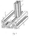
- Both the first profiled bar 1 and the second profiled bar 2 are provided with longitudinal grooves 3, 4, which have a T-shaped cross-section.
- a connecting device is provided with a bar 6 and thus tightened sliding blocks. 5
- the bar 6 is connected via attachment screws 9 end face to the second profiled bar 2, wherein the fastening screws 9 are screwed into longitudinally extending screw channels of the second profiled bar 2 and thereby each pass through hole 10 of the bar 6.
- the longitudinal grooves 3 of the first profiled bar 1 are dimensioned correspondingly larger than the longitudinal grooves 4 of the second profiled bar 2.
- sliding blocks 5 are connected to the bar 6 by clamping screws 7, which are guided through the bar in threaded holes 11 ( Figure 4) are screwed and press the respective sliding block 5 against the undercut of the longitudinal groove 3.
- the heads of the clamping screws 7 protrude into the longitudinal grooves 4 of the second profiled bar 2, that is, they are so far concealed.
- the strip 6 corresponds in its essential width to the clear width of the open part of the longitudinal groove 4 of the second profiled bar 2.
- they are according to the invention on their side facing the open longitudinal side of the longitudinal groove 3 provided with a recess 8 which extends continuously in L Lucassachscardi the longitudinal groove 3 and open on both sides assumes a U-shape.
- this recess 8 is inserted from above bar 6 in a way that it is flush with the associated outside of the first profile bar 1, wherein the sliding block 5 with its the recess 8 bounding side walls extends to the outside or almost to the outside of the first profiled bar 1.
- the sliding block 5 at the diagonally opposite corners each have a chamfer 12, wherein these bevels 12 are parallel.
- the length of the sliding block 5, which is equivalent to the length of the recess 8 corresponds to the clear width of the open area of the longitudinal groove 3, so that the sliding block 5 can initially be inserted from above into the longitudinal groove 3. After a rotation through 90 °, which is made possible by the bevels 12, the nut 5 engages below the undercut of the longitudinal groove 3 in the region of greater width, so that the fixed tension with the bar 6 and thus with the second profile bar 2 is possible.
Landscapes
- Engineering & Computer Science (AREA)
- General Engineering & Computer Science (AREA)
- Mechanical Engineering (AREA)
- Mutual Connection Of Rods And Tubes (AREA)
- Roof Covering Using Slabs Or Stiff Sheets (AREA)
Claims (7)
- Dispositif d'assemblage, destiné à assembler entre elles deux barres profilées (1, 2) disposées en angle l'une par rapport à l'autre, comportant une baguette (6), qui est fixée sur le côté frontal de la deuxième barre profilée (2) et contre laquelle est fixé au moins un coulisseau (5), qui s'engage dans une rainure longitudinale (3) détalonnée de la première barre profilée (1) et enserre celle-ci de derrière, caractérisé en ce que le coulisseau (5), sur son côté orienté vers le côté longitudinal ouvert de la rainure longitudinale (3), comporte un évidement (8), qui est délimité par des parois latérales parallèles à la rainure longitudinale (3) et dans lequel est engagée la baguette (6) insérée à partir du dessus, l'évidement (8) ayant une largeur qui correspond sensiblement à la largeur de la baguette (6).
- Dispositif d'assemblage selon la revendication 1, caractérisé en ce que l'évidement (8) s'étend sur toute la longueur du coulisseau (5).
- Dispositif d'assemblage selon l'une quelconque des revendications précédentes, caractérisé en ce que la profondeur de l'évidement (8) correspond sensiblement à l'épaisseur de la baguette (6).
- Dispositif d'assemblage selon l'une quelconque des revendications précédentes, caractérisé en ce que le coulisseau (5) est muni d'une rampe (12) dans chacune des deux zones d'angle diagonalement opposées.
- Dispositif d'assemblage selon l'une quelconque des revendications précédentes, caractérisé en ce que les rampes (12) sont parallèles entre elles.
- Dispositif d'assemblage selon l'une quelconque des revendications précédentes, caractérisé en ce que deux zones d'angle diagonalement opposées du coulisseau (5) sont arrondies.
- Dispositif d'assemblage selon l'une quelconque des revendications précédentes, caractérisé en ce que la longueur du coulisseau (5) est égale ou légèrement inférieure à la largeur intérieure de la rainure longitudinale (3) dans la zone du côté ouvert vers le côté extérieur de la première barre profilée (1).
Applications Claiming Priority (1)
| Application Number | Priority Date | Filing Date | Title |
|---|---|---|---|
| DE200410043964 DE102004043964A1 (de) | 2004-09-11 | 2004-09-11 | Verbindungsvorrichtung |
Publications (3)
| Publication Number | Publication Date |
|---|---|
| EP1635075A2 EP1635075A2 (fr) | 2006-03-15 |
| EP1635075A3 EP1635075A3 (fr) | 2006-07-12 |
| EP1635075B1 true EP1635075B1 (fr) | 2007-08-22 |
Family
ID=35463651
Family Applications (1)
| Application Number | Title | Priority Date | Filing Date |
|---|---|---|---|
| EP20050019180 Expired - Lifetime EP1635075B1 (fr) | 2004-09-11 | 2005-09-03 | Dispositif de connection |
Country Status (3)
| Country | Link |
|---|---|
| EP (1) | EP1635075B1 (fr) |
| DE (2) | DE102004043964A1 (fr) |
| ES (1) | ES2289632T3 (fr) |
Families Citing this family (6)
| Publication number | Priority date | Publication date | Assignee | Title |
|---|---|---|---|---|
| DE102008006439B4 (de) | 2008-01-28 | 2015-05-21 | Alfer Aluminium Gesellschaft Mbh | Bausatz aus Konstruktionsprofil, Profilverbinder und Tragarmen |
| EP2786026B1 (fr) * | 2011-11-30 | 2015-10-14 | Hartmut Flaig | Barre profilée, assemblage de profilés et procédé de fabrication d'un assemblage de profilés |
| US10954979B1 (en) * | 2018-04-27 | 2021-03-23 | Patrick J. Santini | Hidden extrusion connector |
| GB2608200B (en) * | 2021-10-01 | 2024-08-07 | Tenthouse Structures Pty Ltd | Tensile membrane structure building system |
| DE102021132031A1 (de) | 2021-12-01 | 2023-06-01 | Zoller & Fröhlich GmbH | Modulares System und Klemmhalterung für ein modulares System |
| US20240365974A1 (en) * | 2023-05-03 | 2024-11-07 | Damotech Inc. | Bracket for attaching a support member to a frame member, assembly including the support member and the bracket |
Family Cites Families (10)
| Publication number | Priority date | Publication date | Assignee | Title |
|---|---|---|---|---|
| DE7825830U1 (de) * | 1978-12-21 | Schoen, Otmar, 6601 Scheidterberg | Vorrichtung zum Anbringen einer Haltemutter in einer Halteschiene | |
| DE9006344U1 (de) * | 1990-06-05 | 1990-09-06 | Bahr, Frank, 4952 Porta Westfalica | Vorrichtung zum lösbaren Verbinden von zwei Profilstäben |
| DE9304053U1 (de) * | 1993-03-19 | 1993-05-19 | Festo KG, 7300 Esslingen | Verbindungseinrichtung für Profilteile |
| DE9313596U1 (de) * | 1993-09-09 | 1993-10-21 | RK Rose + Krieger GmbH & Co. KG, 32457 Porta Westfalica | Zwei, durch eine Verbindungseinrichtung lösbar miteinander verbundene Profilstäbe |
| DE4447456C2 (de) * | 1994-03-12 | 1996-05-23 | Diag Design Ag | Montageschiene |
| DE29705977U1 (de) * | 1997-04-04 | 1998-10-08 | Ramsauer, Dieter, 42555 Velbert | Anschraubscharnier für hinterschnittene Nuten aufweisende Profile |
| EP1050691A3 (fr) * | 1999-05-03 | 2003-04-02 | Junker & Partner GmbH | Dispositif de sécurité pour vis |
| DE10052534A1 (de) * | 2000-10-23 | 2002-04-25 | Hilti Ag | Schienenanbinder |
| DE20105343U1 (de) * | 2001-03-26 | 2002-08-08 | Ortwein, Ernst-Georg, 73061 Ebersbach | Montagesystem für Sanitärarmaturen |
| DE20201977U1 (de) * | 2002-02-09 | 2002-04-18 | RK Rose + Krieger GmbH & Co KG Verbindungs- und Positioniersysteme, 32423 Minden | Profilstabverbinder |
-
2004
- 2004-09-11 DE DE200410043964 patent/DE102004043964A1/de not_active Ceased
-
2005
- 2005-09-03 ES ES05019180T patent/ES2289632T3/es not_active Expired - Lifetime
- 2005-09-03 EP EP20050019180 patent/EP1635075B1/fr not_active Expired - Lifetime
- 2005-09-03 DE DE200550001290 patent/DE502005001290D1/de not_active Expired - Lifetime
Also Published As
| Publication number | Publication date |
|---|---|
| ES2289632T3 (es) | 2008-02-01 |
| DE102004043964A1 (de) | 2006-04-06 |
| EP1635075A2 (fr) | 2006-03-15 |
| DE502005001290D1 (de) | 2007-10-04 |
| EP1635075A3 (fr) | 2006-07-12 |
Similar Documents
| Publication | Publication Date | Title |
|---|---|---|
| EP0278252A2 (fr) | Profilé d'ancrage | |
| EP0136431A2 (fr) | Ossature en profilés | |
| DE9100099U1 (de) | Durch Schrauben mit einem Profilstab verbundener Tragstab | |
| EP1764447B9 (fr) | Dispositif pour joint d'about pour façades bois/aluminium | |
| EP0976891B1 (fr) | Système de construction | |
| EP1635075B1 (fr) | Dispositif de connection | |
| DE3319627A1 (de) | Vorrichtung, insbesondere spiegelschrank | |
| EP0004374A1 (fr) | Moyen de liaison de deux profilés | |
| EP1840314B1 (fr) | Composant coupe-feu | |
| AT408561B (de) | Schutzzaun | |
| DE3422222A1 (de) | Gestell aus einem profilstab und daran mit einem verbinder angebrachter platte o. dgl. gestellteil | |
| DE19757089C1 (de) | Verbindungselement zum Verbinden von Profilstäben | |
| EP0623530A1 (fr) | Système de convoyeur aérien avec un set de profilés de montage | |
| DE9100699U1 (de) | Knotenelement | |
| DE19614084C2 (de) | Vorrichtung zum Verbinden von mit hinterschnittenen Längsnuten versehenen Profilstäben | |
| DE29509555U1 (de) | Schaltschrank mit Montageplatte als Einzel- oder Anreihschrank | |
| DE102010028603B3 (de) | Beschlagteil zur Befestigung an einer C-förmigen Beschlagteilnut | |
| EP2078788B1 (fr) | Domaine de croisement d'un croisement de rails à gorges | |
| EP2186959A2 (fr) | Connexion en T entre un poteau profilé et une traverse profilée | |
| DE3209550C2 (de) | Gehäuse für elektrotechnische Geräte | |
| DE4444413A1 (de) | Bausatz für Skelettkonstrukionen wie Regale, Rahmen, Ständer u. dgl. | |
| EP0952267B1 (fr) | Elément pour la connection d'éléments plans de grilles de protection | |
| DE10328404B4 (de) | Verbinder zum mechanisch festen Verbinden zweier senkrecht zueinander verlaufender Profilstangen | |
| DE19717119C1 (de) | Zapfenverbinder zur Stirnverbindung wenigstens eines an einer Verbindungsstelle stirnseitig endenden Holzbalkens mit einem durchlaufenden Holzbalken | |
| EP4575119A1 (fr) | Raccord en t et procédé d'assemblage d'un raccord en t |
Legal Events
| Date | Code | Title | Description |
|---|---|---|---|
| PUAI | Public reference made under article 153(3) epc to a published international application that has entered the european phase |
Free format text: ORIGINAL CODE: 0009012 |
|
| AK | Designated contracting states |
Kind code of ref document: A2 Designated state(s): AT BE BG CH CY CZ DE DK EE ES FI FR GB GR HU IE IS IT LI LT LU LV MC NL PL PT RO SE SI SK TR |
|
| AX | Request for extension of the european patent |
Extension state: AL BA HR MK YU |
|
| PUAL | Search report despatched |
Free format text: ORIGINAL CODE: 0009013 |
|
| AK | Designated contracting states |
Kind code of ref document: A3 Designated state(s): AT BE BG CH CY CZ DE DK EE ES FI FR GB GR HU IE IS IT LI LT LU LV MC NL PL PT RO SE SI SK TR |
|
| AX | Request for extension of the european patent |
Extension state: AL BA HR MK YU |
|
| 17P | Request for examination filed |
Effective date: 20060831 |
|
| 17Q | First examination report despatched |
Effective date: 20061002 |
|
| AKX | Designation fees paid |
Designated state(s): DE ES FR GB IT |
|
| GRAP | Despatch of communication of intention to grant a patent |
Free format text: ORIGINAL CODE: EPIDOSNIGR1 |
|
| GRAS | Grant fee paid |
Free format text: ORIGINAL CODE: EPIDOSNIGR3 |
|
| GRAA | (expected) grant |
Free format text: ORIGINAL CODE: 0009210 |
|
| AK | Designated contracting states |
Kind code of ref document: B1 Designated state(s): DE ES FR GB IT |
|
| REG | Reference to a national code |
Ref country code: GB Ref legal event code: FG4D Free format text: NOT ENGLISH |
|
| REF | Corresponds to: |
Ref document number: 502005001290 Country of ref document: DE Date of ref document: 20071004 Kind code of ref document: P |
|
| GBT | Gb: translation of ep patent filed (gb section 77(6)(a)/1977) |
Effective date: 20070927 |
|
| REG | Reference to a national code |
Ref country code: ES Ref legal event code: FG2A Ref document number: 2289632 Country of ref document: ES Kind code of ref document: T3 |
|
| PLBE | No opposition filed within time limit |
Free format text: ORIGINAL CODE: 0009261 |
|
| STAA | Information on the status of an ep patent application or granted ep patent |
Free format text: STATUS: NO OPPOSITION FILED WITHIN TIME LIMIT |
|
| 26N | No opposition filed |
Effective date: 20080526 |
|
| REG | Reference to a national code |
Ref country code: FR Ref legal event code: PLFP Year of fee payment: 11 |
|
| PGFP | Annual fee paid to national office [announced via postgrant information from national office to epo] |
Ref country code: GB Payment date: 20150922 Year of fee payment: 11 Ref country code: ES Payment date: 20150923 Year of fee payment: 11 |
|
| PGFP | Annual fee paid to national office [announced via postgrant information from national office to epo] |
Ref country code: FR Payment date: 20150923 Year of fee payment: 11 |
|
| PGFP | Annual fee paid to national office [announced via postgrant information from national office to epo] |
Ref country code: DE Payment date: 20151005 Year of fee payment: 11 Ref country code: IT Payment date: 20150925 Year of fee payment: 11 |
|
| REG | Reference to a national code |
Ref country code: DE Ref legal event code: R119 Ref document number: 502005001290 Country of ref document: DE |
|
| GBPC | Gb: european patent ceased through non-payment of renewal fee |
Effective date: 20160903 |
|
| REG | Reference to a national code |
Ref country code: FR Ref legal event code: ST Effective date: 20170531 |
|
| PG25 | Lapsed in a contracting state [announced via postgrant information from national office to epo] |
Ref country code: DE Free format text: LAPSE BECAUSE OF NON-PAYMENT OF DUE FEES Effective date: 20170401 Ref country code: FR Free format text: LAPSE BECAUSE OF NON-PAYMENT OF DUE FEES Effective date: 20160930 Ref country code: GB Free format text: LAPSE BECAUSE OF NON-PAYMENT OF DUE FEES Effective date: 20160903 |
|
| PG25 | Lapsed in a contracting state [announced via postgrant information from national office to epo] |
Ref country code: IT Free format text: LAPSE BECAUSE OF NON-PAYMENT OF DUE FEES Effective date: 20160903 |
|
| PG25 | Lapsed in a contracting state [announced via postgrant information from national office to epo] |
Ref country code: ES Free format text: LAPSE BECAUSE OF NON-PAYMENT OF DUE FEES Effective date: 20160904 |
|
| REG | Reference to a national code |
Ref country code: ES Ref legal event code: FD2A Effective date: 20181128 |