EP1635237B1 - Robot nettoyeur - Google Patents
Robot nettoyeur Download PDFInfo
- Publication number
- EP1635237B1 EP1635237B1 EP05008330A EP05008330A EP1635237B1 EP 1635237 B1 EP1635237 B1 EP 1635237B1 EP 05008330 A EP05008330 A EP 05008330A EP 05008330 A EP05008330 A EP 05008330A EP 1635237 B1 EP1635237 B1 EP 1635237B1
- Authority
- EP
- European Patent Office
- Prior art keywords
- link member
- supporter
- wheel
- cleaner body
- robot cleaner
- Prior art date
- Legal status (The legal status is an assumption and is not a legal conclusion. Google has not performed a legal analysis and makes no representation as to the accuracy of the status listed.)
- Expired - Lifetime
Links
- 230000000994 depressogenic effect Effects 0.000 claims description 27
- 238000006073 displacement reaction Methods 0.000 claims description 8
- 238000004140 cleaning Methods 0.000 description 12
- 239000000126 substance Substances 0.000 description 3
- 230000005540 biological transmission Effects 0.000 description 2
- 230000003247 decreasing effect Effects 0.000 description 2
- 230000003287 optical effect Effects 0.000 description 2
- 230000001680 brushing effect Effects 0.000 description 1
- 230000008878 coupling Effects 0.000 description 1
- 238000010168 coupling process Methods 0.000 description 1
- 238000005859 coupling reaction Methods 0.000 description 1
- 238000001914 filtration Methods 0.000 description 1
- 238000000034 method Methods 0.000 description 1
- 238000012986 modification Methods 0.000 description 1
- 230000004048 modification Effects 0.000 description 1
Images





Classifications
-
- A—HUMAN NECESSITIES
- A47—FURNITURE; DOMESTIC ARTICLES OR APPLIANCES; COFFEE MILLS; SPICE MILLS; SUCTION CLEANERS IN GENERAL
- A47L—DOMESTIC WASHING OR CLEANING; SUCTION CLEANERS IN GENERAL
- A47L11/00—Machines for cleaning floors, carpets, furniture, walls, or wall coverings
-
- A—HUMAN NECESSITIES
- A47—FURNITURE; DOMESTIC ARTICLES OR APPLIANCES; COFFEE MILLS; SPICE MILLS; SUCTION CLEANERS IN GENERAL
- A47L—DOMESTIC WASHING OR CLEANING; SUCTION CLEANERS IN GENERAL
- A47L9/00—Details or accessories of suction cleaners, e.g. mechanical means for controlling the suction or for effecting pulsating action; Storing devices specially adapted to suction cleaners or parts thereof; Carrying-vehicles specially adapted for suction cleaners
- A47L9/009—Carrying-vehicles; Arrangements of trollies or wheels; Means for avoiding mechanical obstacles
-
- A—HUMAN NECESSITIES
- A47—FURNITURE; DOMESTIC ARTICLES OR APPLIANCES; COFFEE MILLS; SPICE MILLS; SUCTION CLEANERS IN GENERAL
- A47L—DOMESTIC WASHING OR CLEANING; SUCTION CLEANERS IN GENERAL
- A47L9/00—Details or accessories of suction cleaners, e.g. mechanical means for controlling the suction or for effecting pulsating action; Storing devices specially adapted to suction cleaners or parts thereof; Carrying-vehicles specially adapted for suction cleaners
- A47L9/28—Installation of the electric equipment, e.g. adaptation or attachment to the suction cleaner; Controlling suction cleaners by electric means
-
- G—PHYSICS
- G05—CONTROLLING; REGULATING
- G05D—SYSTEMS FOR CONTROLLING OR REGULATING NON-ELECTRIC VARIABLES
- G05D1/00—Control of position, course, altitude or attitude of land, water, air or space vehicles, e.g. using automatic pilots
- G05D1/02—Control of position or course in two dimensions
- G05D1/021—Control of position or course in two dimensions specially adapted to land vehicles
- G05D1/0212—Control of position or course in two dimensions specially adapted to land vehicles with means for defining a desired trajectory
- G05D1/0225—Control of position or course in two dimensions specially adapted to land vehicles with means for defining a desired trajectory involving docking at a fixed facility, e.g. base station or loading bay
-
- G—PHYSICS
- G05—CONTROLLING; REGULATING
- G05D—SYSTEMS FOR CONTROLLING OR REGULATING NON-ELECTRIC VARIABLES
- G05D1/00—Control of position, course, altitude or attitude of land, water, air or space vehicles, e.g. using automatic pilots
- G05D1/02—Control of position or course in two dimensions
- G05D1/021—Control of position or course in two dimensions specially adapted to land vehicles
- G05D1/0227—Control of position or course in two dimensions specially adapted to land vehicles using mechanical sensing means, e.g. for sensing treated area
-
- A—HUMAN NECESSITIES
- A47—FURNITURE; DOMESTIC ARTICLES OR APPLIANCES; COFFEE MILLS; SPICE MILLS; SUCTION CLEANERS IN GENERAL
- A47L—DOMESTIC WASHING OR CLEANING; SUCTION CLEANERS IN GENERAL
- A47L2201/00—Robotic cleaning machines, i.e. with automatic control of the travelling movement or the cleaning operation
- A47L2201/04—Automatic control of the travelling movement; Automatic obstacle detection
Definitions
- the present invention relates to a robot cleaner, and particularly, to a robot cleaner capable of stably carrying out cleaning operation by sensing a depressed portion or a stepped portion such as a doorsill of a floor and thus by avoiding, passing, crossing over or going over such portions.
- a robot cleaner is a device that automatically moves in a cleaning area, carrying out cleaning operation, moves to a charging station when a charging voltage of a battery is decreased below a predetermined level, and returns to the cleaning area when the charging is completed to perform the cleaning operation.
- the robot cleaner is provided with a suction unit for sucking foreign substances on a floor; a driving unit comprised of a driving motor and a driving wheel connected to the driving motor to move the robot cleaner; a navigation sensor for sensing a position and a cleaning area of the robot cleaner; and a control unit for automatically controlling the robot cleaner.
- the conventional robot cleaner cannot continuously perform cleaning by falling to a depressed portion or being caught by a stepped portion such as a doorsill because it cannot sense the depressed portion making a relatively great height difference with a bottom of the robot cleaner or the stepped portion in the cleaning area.
- Document GB 2 278 937 A discloses a robot cleaner comprising a mechanical sensing means for sensing a depressed portion and a stepped portion such as a doorsill of a floor.
- an object of the present invention is to provide a robot cleaner capable of stably carrying out cleaning operation by being provided with a sensing unit having a mechanical structure to correctly sense a depressed portion or a stepped portion such as a doorsill of a floor.
- a robot cleaner comprising: a suction unit installed at a cleaner body, for sucking dirt on a floor; a driving unit for moving the cleaner body; a sensing unit mounted at the cleaner body, for sensing a depressed portion and a stepped portion such as a doorsill of a floor; and a control unit receiving a signal of the sensing unit, for controlling the driving unit to allow the cleaner body to avoid the depressed portion and the stepped portion.
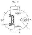
- a robot cleaner in accordance with the present invention includes: a suction unit 60 installed at a cleaner body 1 for sucking dirt on a floor; a driving unit 50 for moving the cleaner body 1; at least one navigation sensor 30 installed at one side of the cleaner body 1, for determining a position of the cleaner body 1 and a position of an obstacle or the like when the cleaner body moves; a control unit 10 for controlling the suction unit 60 and the driving unit 50 according to a signal from the navigation sensor 30; and a sensing unit 100 mounted to the cleaner body 1 and having a mechanical structure to sense a depressed portion and a stepped portion of a floor.
- a battery 21 is installed in the cleaner body 1, and a charging terminal part 23 having a charging terminal 22 connected to a connection terminal 26 of a power terminal part 25 installed on a wall of a room to thereby charge the battery 21 is provided at a rear side of the cleaner body 1.
- a light emitting part 41 for emitting an optical signal for guiding the cleaner body 1 to the power terminal part 25 is installed at a lower side of the power terminal part 25, and a light receiving part 42 for receiving the optical signal emitted from the light emitting part 41 is installed at a lower side of the charging terminal part 23.
- the suction unit 60 includes: a fan motor 2 installed inside the cleaner body 1, for generating a suction force; a filter container 4 installed at the rear of the fan motor 2, for receiving a filter 3 for filtering foreign substances such as dirt or the like sucked by the fan motor 2; a suction head 6 provided at a bottom of the cleaner body 1 and connected to the filter container 4 through a connection pipe 5, for sucking foreign substances on a floor; and a brush 7 rotatably disposed in the suction head 6, for brushing dirt on the floor.
- the driving unit 50 includes: a driving wheel 8 rotatably installed at the cleaner body 1; a driving motor 51 for rotating the driving wheel 8; and at least one support wheel 9 installed at a bottom of the cleaner body 1, for supporting the cleaner body 1 on a floor, the support wheel 9 idled by a movement of the cleaner body 1.
- the navigation sensor 30 includes: an ultrasonic wave transmission unit 31 installed at the front side of the cleaner body 1, for transmitting ultrasonic waves; and an ultrasonic wave reception unit 32 installed around the ultrasonic wave transmission unit 31 in plurality, for sensing ultrasonic waves reflected by obstacles or the like.
- the sensing unit 100 is installed at a front side in a moving direction of the cleaner body 1 on the basis of the suction head 6 of the suction unit 60, and senses a depressed portion or a stepped portion like a doorsill of a floor while the cleaner body 1 travels.
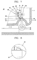
- the sensing unit 100 includes: a wheel 101 positioned with its one portion inserted in a recessed portion 1a recessed in the bottom of the cleaner body 1 at a predetermined depth, and displaced in a vertical direction according to prominence and depression of the floor while being idled by a movement of the cleaner body 1 in a state of contacting with a floor; a connection rod 102 hinge-connected to a rotary shaft 101a protruding from the rotation center of the wheel 101, and extended toward the inside of the cleaner body 1; a supporter 105 fixed to a bracket 106, which is fixed inside the cleaner body 1, through a coupling means such as a screw 108 or the like; a first link member 103 whose one end is hinge-connected to an upper end of the supporter 105 through a first pin 107a and whose other end is hinge-connected to an upper end of the connection rod 102 through a second pin 107b; a second link member 104 whose one end is hinge-connected to the support
- the sensing unit 120 includes first and second contact switches 121 and 122 fixed to the bracket 106 and respectively coming in contact with the first and second link members 103 and 104 pivoted by a displacement in a vertical direction of the wheel 101.
- the first contact switch 121 is installed above the first link member 103, and comes in contact with the first link member 103 pivoted on the first pin 107a when the wheel 101 and the connection rod 102 move upward.
- the second contact switch 122 is installed under the second link member 104, and comes in contact with the second link member 104 pivoted on the third pin 107c when the wheel 101 and the connection rod 102 move downward.
- the control unit 10 and the navigation sensor 130 are operated, and the driving wheel 8 connected to the driving motor 51 is rotated, moving in a cleaning area according to a set pattern. And, as the fan motor 2 is driven, dirt on a floor is introduced to the filter 3 through the suction head 6 and the connection pipe 5, and is filtered. In such a manner, the cleaning operation is carried out.
- FIG. 9 shows another example of a sensing unit for sensing a depressed portion and a stepped portion such as a doorsill in a robot cleaner in accordance with the present invention.
- the sensing unit 100 is provided with an elastic member 130 whose one end is fixed to the bracket 106 of the cleaner body 1 and whose other end is fixed to the first or second link member 103 or 104, so that the wheel 101, the connection rod 102, and the first and second link members 103 and 104 move smoothly.
- the elastic member 130 provides a preset elastic force to the first and second link members 103 and 104, the connection rod 102 and the wheel 101.
- a force for rotating the first and second link members 130 and 140 about the first and second pins 107 and 107c clockwise on FIG. 9 works on the first and second link members 130 and 104.
- the wheel 101 can correctly react to a floor condition.
- undesired shaking of the wheel 101, the connection rod 102 and the first and second link members 103 and 104, which may be generated when the wheel 101 meets the depressed portion or the stepped portion such as a doorsill, can be prevented.
- the wheel 101 descends by not only its weight but also an elastic force of the elastic member 130. Therefore, the wheel 101, the connection rod 102 and the first and second link members 103 and 104 speedily move, so that the operation for sensing the depressed portion of the floor is quickly made.
- the elastic member 130 is not limited by connection with the first or the second link member 103 or 104, but may be connected to the connection rod 102 or the wheel 101, thereby applying a downward force to the wheel 101.
- FIG. 10 shows still another example of a sensing unit for sensing the depressed portion and the stepped portion such as a doorsill in a robot cleaner in accordance with the present invention.
- a sensing unit 200 installed at a cleaner body 1 for sensing the depressed portion and the stepped portion includes: a wheel 201 positioned with its one portion inserted in a recessed portion 1 a recessed in a bottom of a front side of the cleaner body 1 at a predetermined depth, idled by a movement of the cleaner body 1 in a state of contacting with a floor, and displaced in a vertical direction according to the prominence and depression of the floor; a connection rod 202 hinge-connected to a rotary shaft 201a protruding from the rotation center of the wheel 201 and extended toward the inside of the cleaner body 1; a supporter 205 pivotally connected to a bracket 206, which is fixed inside the cleaner body 1, through a first pin 207a; a first link member 203 whose one end is hinge-connected to an upper end of the supporter205 through the first pin 207a and whose other end is hinge-connected to an upper end of the connection rod 202 through a second pin 207b; a second link member
- the sensing unit 220 includes: a first contact switch 221 installed at a position adjacent to the first link member 203 of the supporter 205 and coming in contact with the first link member 203 pivoted by a displacement in a vertical direction of the wheel 202; and a second contact switch installed at a position adjacent to the second link member 204 of the supporter 205 and coming in contact with the second link member 204 pivoted by a displacement in a vertical direction of the wheel 202.
- the elastic member 230 is connected to a lower portion of the supporter 205 on the basis of the rotation center of the supporter 205, namely, the center of the first pin 207a and provides an elastic force for rotating the lower portion of the supporter 205 toward a rear side of the cleaner body 1. Namely, a force for rotating the supporter 205 about the first pin 207a clockwise on FIG. 10 works on the supporter 205.
- the supporter 205 maintains its stopped state by the stopper 209.
- the cleaner body 1 meets the stepped portion such as a doorsill, the wheel 201 ascends by the stepped portion, and the connection rod 202 also ascends. Accordingly, the first and second link members 203 and 204 are respectively rotated about the first and third pins 207a and 207c connected to the supporter 205 counterclockwise on FIG. 10 .
- the wheel 201 descends by its own weight, and the connection rod 202 descends, too. Accordingly, the first and second link members 203 and 204 are respectively rotated about the first and third pins 207a and 207c connected to the supporter clockwise on FIG. 10 .
- the stopper 209 prevents the supporter from being rotated at the certain angle or more.
- the resistance generated at the wheel 201 and the connection rod 202 is decreased by the rotatably installed supporter 205 and the elastic member 209 which provides an elastic force to the supporter 205.
- the robot cleaner in accordance with the present invention is provided with a sensing unit having a mechanical structure to correctly sense a depressed portion or a stepped portion such a doorsill of a floor during traveling, thereby stably carrying out the cleaning operation.
Landscapes
- Engineering & Computer Science (AREA)
- Aviation & Aerospace Engineering (AREA)
- Radar, Positioning & Navigation (AREA)
- Remote Sensing (AREA)
- Physics & Mathematics (AREA)
- General Physics & Mathematics (AREA)
- Automation & Control Theory (AREA)
- Mechanical Engineering (AREA)
- Electric Vacuum Cleaner (AREA)
- Control Of Position, Course, Altitude, Or Attitude Of Moving Bodies (AREA)
- Electric Suction Cleaners (AREA)
Claims (12)
- Robot nettoyeur comprenant :une unité d'aspiration (60) installée sur un corps de nettoyeur (1) pour aspirer la poussière sur un sol ;une unité d'entraînement (50) pour déplacer le corps de nettoyeur (1) ;une unité de détection (100 ; 200) montée sur le corps de nettoyeur (1) pour détecter une partie en creux et une partie étagée comme le seuil de porte d'un sol ; etune unité de commande (10) recevant un signal de l'unité de détection (100 ; 200) pour commander l'unité d'entraînement (50) afin de permettre au corps de nettoyeur (1) d'éviter la partie en creux et la partie étagée ;caractérisé en ce que l'unité de détection (100 ; 200) comprend :une roue (101 ; 201) installée sur une partie inférieure du corps de nettoyeur (1) dans un état en contact avec un sol, ralentie par un mouvement du corps de nettoyeur (1) et déplacée dans une direction verticale selon la proéminence et la dépression du sol ;une tige de liaison (102 ; 202) reliée à la roue (101 ; 201) et étendue en direction de l'intérieur du corps de nettoyeur (1) ;un support (105 ; 205) installé sur le corps de nettoyeur (1) ;un premier élément de liaison (103 ; 203) dont une extrémité est reliée de manière articulée à une extrémité supérieure du support (105 ; 205) et dont l'autre extrémité est reliée de manière articulée à une extrémité supérieure de la tige de liaison (102 ; 202) ;un second élément de liaison (104 ; 204) dont une extrémité est reliée de manière articulée au support (105 ; 205) à une distance prédéterminée d'une position du support (105 ; 205) dans laquelle le premier élément de liaison (103 ; 203) est relié, et dont l'autre extrémité est reliée de manière articulée à la tige de liaison (102 ; 202) à une distance prédéterminée d'une position de la tige de liaison (102 ; 202) dans laquelle le premier élément de liaison (103 ; 203) est relié ; etune unité de détection (120 ; 220) pour détecter la quantité de déplacement dans une direction verticale de la roue (101 ; 201).
- Robot nettoyeur selon la revendication 1, dans lequel le premier élément de liaison (103 ; 203) et le second élément de liaison (105 ; 205) sont installés pour maintenir une liaison parallèle entre eux.
- Robot nettoyeur selon la revendication 1, dans lequel l'unité de détection (120 ; 220) comprend :des premier (121 ; 221) et second interrupteurs de contact (122 ; 222) fixés sur le corps de nettoyeur (1) et venant respectivement en contact avec les premier (103 ; 203) et second éléments de liaison (104 ; 204) pivotés par un déplacement dans une direction verticale de la roue (101 ; 201).
- Robot nettoyeur selon la revendication 3, dans lequel le premier interrupteur de contact (121 ; 221) est installé au-dessus du premier élément de liaison (103 ; 203) et vient en contact avec le premier élément de liaison (103 ; 203) pivoté lorsque la roue (101 ; 201) et la tige de liaison (102 ; 202) se déplacent vers le haut, et le second interrupteur de contact (122 ; 222) est installé sous le second élément de liaison (104 ; 204) et vient en contact avec le second élément de liaison (104 ; 204) pivoté lorsque la roue (101 ; 201) et la tige de liaison (102 ; 202) se déplacent vers le bas.
- Robot nettoyeur selon la revendication 1, dans lequel un élément élastique (130) pour fournir une force élastique au premier (103) ou au second élément de liaison (104) est installé entre le premier (103) ou le second élément de liaison (104) et le corps de nettoyeur (1).
- Robot nettoyeur selon la revendication 1, dans lequel l'unité de détection (100 ; 200) est installée sur un côté avant dans une direction de déplacement du corps de nettoyeur (1) sur la base d'une tête d'aspiration (6) de l'unité d'aspiration (60).
- Robot nettoyeur selon la revendication 1, dans lequel le
support (205) est installé de manière à pouvoir tourner sur une fixation (206) fixée sur le corps de nettoyeur (1) ; et
un élément élastique (230) est installé entre le support (205) et la fixation (206), pour fournir une force élastique au support (205). - Robot nettoyeur selon la revendication 7, dans lequel une butée (209) est installée sur la fixation (206), la butée (209) empêchant la rotation du support (205) à un angle prédéterminé ou supérieur.
- Robot nettoyeur selon la revendication 7, dans lequel l'élément élastique (230) est relié à une partie inférieure du centre de rotation du support (205).
- Robot nettoyeur selon la revendication 7, dans lequel l'unité de détection (220) comprend :des premier (221) et second interrupteurs de contact (222) installés adjacents aux premier (203) et au second éléments de liaison (204) et venant respectivement en contact avec les premier (203) et second éléments de liaison (204) pivotés par un déplacement dans une direction verticale de la roue (201).
- Robot nettoyeur selon la revendication 10, dans lequel les premier (221) et second interrupteurs de contact (222) sont installés sur le support (205).
- Robot nettoyeur selon la revendication 10, dans lequel le premier interrupteur de contact (221) est installé au-dessus du premier élément de liaison (203) et vient en contact avec le premier élément de liaison (203) pivoté lorsque la roue (201) et la tige de liaison (202) se déplacent vers le haut, et le second interrupteur de contact (222) est installé sous le second élément de liaison (204) et vient en contact avec le second élément de liaison (204) pivoté lorsque la roue (201) et la tige de liaison (202) se déplacent vers le bas.
Applications Claiming Priority (1)
| Application Number | Priority Date | Filing Date | Title |
|---|---|---|---|
| KR1020040073091A KR100595571B1 (ko) | 2004-09-13 | 2004-09-13 | 로봇 청소기 |
Publications (3)
| Publication Number | Publication Date |
|---|---|
| EP1635237A2 EP1635237A2 (fr) | 2006-03-15 |
| EP1635237A3 EP1635237A3 (fr) | 2007-11-21 |
| EP1635237B1 true EP1635237B1 (fr) | 2012-08-29 |
Family
ID=36604423
Family Applications (1)
| Application Number | Title | Priority Date | Filing Date |
|---|---|---|---|
| EP05008330A Expired - Lifetime EP1635237B1 (fr) | 2004-09-13 | 2005-04-16 | Robot nettoyeur |
Country Status (4)
| Country | Link |
|---|---|
| US (1) | US7581282B2 (fr) |
| EP (1) | EP1635237B1 (fr) |
| KR (1) | KR100595571B1 (fr) |
| CN (1) | CN100409795C (fr) |
Families Citing this family (66)
| Publication number | Priority date | Publication date | Assignee | Title |
|---|---|---|---|---|
| KR101812021B1 (ko) * | 2011-09-30 | 2017-12-27 | 삼성전자주식회사 | 로봇청소기 |
| JP2006113952A (ja) * | 2004-10-18 | 2006-04-27 | Funai Electric Co Ltd | 充電式走行システム |
| KR100664061B1 (ko) * | 2004-12-28 | 2007-01-03 | 엘지전자 주식회사 | 턱등반장치를 구비한 로봇 |
| DE602007007026D1 (de) * | 2006-09-05 | 2010-07-22 | Lg Electronics Inc | Reinigungsroboter |
| KR100835968B1 (ko) * | 2007-02-28 | 2008-06-09 | 엘지전자 주식회사 | 로봇청소기 및 그에 따른 제어방법 |
| KR101487787B1 (ko) * | 2007-08-21 | 2015-02-06 | 삼성전자주식회사 | 진공청소기용 흡입브러시 |
| KR100863187B1 (ko) * | 2008-01-10 | 2008-10-13 | (주)다사로봇 | 지능형 로봇 장치의 제어시스템 및 그 제어방법 |
| TWI361370B (en) * | 2008-10-15 | 2012-04-01 | Primax Electronics Ltd | Mouse system with automatic charging function |
| KR101331706B1 (ko) * | 2009-06-30 | 2013-11-20 | 엘지전자 주식회사 | 로봇청소기 |
| DE102010017689A1 (de) * | 2010-07-01 | 2012-01-05 | Vorwerk & Co. Interholding Gmbh | Selbsttätig verfahrbares Gerät sowie Verfahren zur Orientierung eines solchen Gerätes |
| KR101483541B1 (ko) * | 2010-07-15 | 2015-01-19 | 삼성전자주식회사 | 로봇청소기, 메인터넌스 스테이션 그리고 이들을 가지는 청소시스템 |
| CN102178492A (zh) * | 2010-11-10 | 2011-09-14 | 柯约瑟 | 地板清洁机的自动转向架构 |
| PL394570A1 (pl) | 2011-04-15 | 2012-10-22 | Robotics Inventions Spólka Z Ograniczona Odpowiedzialnoscia | Robot do podlóg podniesionych i sposób serwisowania podlóg podniesionych |
| KR101311295B1 (ko) * | 2011-07-13 | 2013-09-25 | 주식회사 유진로봇 | 이동 로봇의 휠 조립체 |
| KR101931362B1 (ko) * | 2011-08-22 | 2018-12-24 | 삼성전자주식회사 | 로봇청소기 및 그 제어방법 |
| KR101931365B1 (ko) * | 2011-08-22 | 2018-12-24 | 삼성전자주식회사 | 로봇청소기 및 그 제어방법 |
| GB2494446B (en) * | 2011-09-09 | 2013-12-18 | Dyson Technology Ltd | Autonomous cleaning appliance |
| GB2494443B (en) * | 2011-09-09 | 2013-08-07 | Dyson Technology Ltd | Autonomous surface treating appliance |
| US20140201941A1 (en) * | 2011-09-29 | 2014-07-24 | Sharp Kabushiki Kaisha | Cleaning robot |
| CN103356122A (zh) * | 2012-04-05 | 2013-10-23 | 科沃斯机器人科技(苏州)有限公司 | 擦玻璃装置 |
| JP5957296B2 (ja) * | 2012-05-31 | 2016-07-27 | シャープ株式会社 | 充電式電気掃除機 |
| EP3104194B1 (fr) | 2012-08-27 | 2019-02-06 | Aktiebolaget Electrolux | Système de positionnement de robot |
| GB201301578D0 (en) | 2013-01-29 | 2013-03-13 | Dyson Technology Ltd | Mobile robot |
| CN110448222A (zh) | 2013-04-15 | 2019-11-15 | 伊莱克斯公司 | 机器人真空吸尘器 |
| CN105101855A (zh) | 2013-04-15 | 2015-11-25 | 伊莱克斯公司 | 具有伸出的侧刷的机器人真空吸尘器 |
| JP6189636B2 (ja) * | 2013-05-21 | 2017-08-30 | 東芝ライフスタイル株式会社 | 電気掃除機 |
| CN104216404B (zh) * | 2013-05-31 | 2017-02-15 | 科沃斯机器人股份有限公司 | 一种自移动装置及其控制方法 |
| JP6494118B2 (ja) | 2013-12-19 | 2019-04-03 | アクチエボラゲット エレクトロルックス | 障害物の乗り上げの検出に伴うロボット掃除機の制御方法、並びに、当該方法を有するロボット掃除機、プログラム、及びコンピュータ製品 |
| WO2015090404A1 (fr) | 2013-12-19 | 2015-06-25 | Aktiebolaget Electrolux | Priorisation de zones de nettoyage |
| WO2015090397A1 (fr) | 2013-12-19 | 2015-06-25 | Aktiebolaget Electrolux | Dispositif de nettoyage robotique |
| EP3082537B1 (fr) | 2013-12-19 | 2020-11-18 | Aktiebolaget Electrolux | Dispositif de nettoyage robotisé et procédé de reconnaissance de point de repère |
| EP3084538B1 (fr) | 2013-12-19 | 2017-11-01 | Aktiebolaget Electrolux | Dispositif de nettoyage robotisé à fonction d'enregistrement de périmètre |
| ES2675786T3 (es) | 2013-12-19 | 2018-07-12 | Aktiebolaget Electrolux | Control de velocidad adaptativo de cepillo lateral rotatorio |
| US10045675B2 (en) | 2013-12-19 | 2018-08-14 | Aktiebolaget Electrolux | Robotic vacuum cleaner with side brush moving in spiral pattern |
| CN105848545B (zh) | 2013-12-20 | 2019-02-19 | 伊莱克斯公司 | 灰尘容器 |
| JP6207388B2 (ja) * | 2013-12-27 | 2017-10-04 | シャープ株式会社 | 自走式電気掃除機 |
| CN103977982A (zh) * | 2014-05-06 | 2014-08-13 | 太仓万冠涂装设备有限公司 | 一种自动化粉末回收装置 |
| US10518416B2 (en) | 2014-07-10 | 2019-12-31 | Aktiebolaget Electrolux | Method for detecting a measurement error in a robotic cleaning device |
| EP3190939B1 (fr) | 2014-09-08 | 2021-07-21 | Aktiebolaget Electrolux | Aspirateur robot autonomous |
| CN106659344B (zh) | 2014-09-08 | 2019-10-25 | 伊莱克斯公司 | 机器人真空吸尘器 |
| WO2016091291A1 (fr) | 2014-12-10 | 2016-06-16 | Aktiebolaget Electrolux | Utilisation d'un capteur laser pour la détection d'un type de sol |
| US10874271B2 (en) | 2014-12-12 | 2020-12-29 | Aktiebolaget Electrolux | Side brush and robotic cleaner |
| EP3234714B1 (fr) | 2014-12-16 | 2021-05-12 | Aktiebolaget Electrolux | Feuille de route basée sur l'expérience pour un dispositif de nettoyage robotisé |
| WO2016095966A1 (fr) | 2014-12-16 | 2016-06-23 | Aktiebolaget Electrolux | Procédé de nettoyage pour un dispositif de nettoyage robotisé |
| KR102023966B1 (ko) * | 2015-02-10 | 2019-09-23 | 에브리봇 주식회사 | 로봇 청소기 및 그의 제어 방법 |
| CN106142045B (zh) * | 2015-04-15 | 2019-01-22 | 小米科技有限责任公司 | 一种行走装置 |
| US11099554B2 (en) | 2015-04-17 | 2021-08-24 | Aktiebolaget Electrolux | Robotic cleaning device and a method of controlling the robotic cleaning device |
| EP3344104B1 (fr) | 2015-09-03 | 2020-12-30 | Aktiebolaget Electrolux | Système de dispositifs de nettoyage robotisés |
| CN105534413A (zh) * | 2016-02-14 | 2016-05-04 | 海安欣凯富机械科技有限公司 | 除尘装置的控制方法 |
| WO2017157421A1 (fr) | 2016-03-15 | 2017-09-21 | Aktiebolaget Electrolux | Dispositif de nettoyage robotique et procédé au niveau du dispositif de nettoyage robotique pour effectuer une détection de falaise |
| WO2017194102A1 (fr) | 2016-05-11 | 2017-11-16 | Aktiebolaget Electrolux | Dispositif de nettoyage robotisé |
| CN110621208A (zh) | 2017-06-02 | 2019-12-27 | 伊莱克斯公司 | 检测机器人清洁设备前方的表面的高度差的方法 |
| CN110573050A (zh) * | 2017-06-07 | 2019-12-13 | 千叶工业大学 | 自走式扫除机 |
| US10239370B2 (en) * | 2017-08-02 | 2019-03-26 | AI Incorporated | Wheel suspension system |
| CN107361693A (zh) * | 2017-08-28 | 2017-11-21 | 合肥立腾信息科技有限责任公司 | 一种智能扫地机 |
| JP6989210B2 (ja) | 2017-09-26 | 2022-01-05 | アクチエボラゲット エレクトロルックス | ロボット清掃デバイスの移動の制御 |
| CN107981799B (zh) * | 2017-11-26 | 2020-04-17 | 林虹 | 一种清洁机器人 |
| CN107969994A (zh) * | 2017-12-31 | 2018-05-01 | 苏州金丝鸟机器人科技有限公司 | 一种虹吸式供水的安防清洁机器人 |
| CN109340335B (zh) * | 2018-09-11 | 2021-08-24 | 安克创新科技股份有限公司 | 一种智能自移动设备及其减速装置 |
| CN113961005A (zh) | 2018-10-22 | 2022-01-21 | 科沃斯机器人股份有限公司 | 行进控制的方法、表面清洁机器人及存储介质 |
| KR102867521B1 (ko) * | 2019-07-31 | 2025-10-10 | 엘지전자 주식회사 | 청소기 |
| WO2021020680A1 (fr) * | 2019-07-31 | 2021-02-04 | 엘지전자 주식회사 | Aspirateur |
| CN110703872A (zh) * | 2019-09-27 | 2020-01-17 | 湖南文理学院 | 一种可防止散热电扇积尘的计算机用主机箱 |
| CN112220402B (zh) * | 2020-10-20 | 2021-08-06 | 淮北暴风工业设计有限公司 | 一种扫地机器人行走机构 |
| CN115590409A (zh) * | 2022-10-26 | 2023-01-13 | 科沃斯机器人股份有限公司(Cn) | 清洁设备及底盘系统 |
| WO2025049164A1 (fr) * | 2023-08-29 | 2025-03-06 | The Toro Company | Mécanisme de cognement/levage pour machine robotisée de soins au sol |
Family Cites Families (18)
| Publication number | Priority date | Publication date | Assignee | Title |
|---|---|---|---|---|
| US4934018A (en) * | 1988-08-18 | 1990-06-19 | Fabrication Specialists, Inc. | Parallel arm car wash dryer with multispeed contour follow |
| KR920007560Y1 (ko) * | 1990-12-28 | 1992-10-16 | 주식회사 금성사 | 자동주행청소기의 먼지흡입구 승강장치 |
| JPH0678863A (ja) * | 1991-07-15 | 1994-03-22 | Nec Home Electron Ltd | 自走式掃除機 |
| US5440216A (en) | 1993-06-08 | 1995-08-08 | Samsung Electronics Co., Ltd. | Robot cleaner |
| JP3345982B2 (ja) * | 1993-09-14 | 2002-11-18 | 松下電器産業株式会社 | 移動作業ロボット |
| JPH07331242A (ja) * | 1994-06-15 | 1995-12-19 | Showa Denko Kk | 光学活性化合物およびそれを含む液晶組成物 |
| US6594844B2 (en) * | 2000-01-24 | 2003-07-22 | Irobot Corporation | Robot obstacle detection system |
| AUPR154400A0 (en) | 2000-11-17 | 2000-12-14 | Duplex Cleaning Machines Pty. Limited | Robot machine |
| ITFI20010021A1 (it) | 2001-02-07 | 2002-08-07 | Zucchetti Ct Sistemi S P A | Apparecchio pulitore aspirante automatico per pavimenti |
| EP1395888B1 (fr) * | 2001-06-12 | 2011-05-18 | iRobot Corporation | Procede et systeme de couverture multimode pour un robot autonome |
| ATE309736T1 (de) | 2001-09-14 | 2005-12-15 | Vorwerk Co Interholding | Selbsttätig verfahrbares bodenstaub- aufsammelgerät, sowie kombination eines derartigen aufsammelgerätes und einer basisstaton |
| CN1229069C (zh) | 2002-01-06 | 2005-11-30 | 海尔集团公司 | 自动升降地板刷 |
| CN1436511A (zh) * | 2002-02-05 | 2003-08-20 | 海尔集团公司 | 智能吸尘器 |
| US7025834B2 (en) * | 2002-09-04 | 2006-04-11 | Tennant Company | Retractable broom and dust skirt |
| JP2004139264A (ja) | 2002-10-16 | 2004-05-13 | Toshiba Tec Corp | 自律走行ロボット |
| KR100492577B1 (ko) * | 2002-10-22 | 2005-06-03 | 엘지전자 주식회사 | 로봇 청소기의 흡입헤드 |
| CN2631410Y (zh) | 2003-07-10 | 2004-08-11 | 刘宝会 | 吸尘器 |
| KR20050063547A (ko) * | 2003-12-22 | 2005-06-28 | 엘지전자 주식회사 | 로봇 청소기 및 그 운전방법 |
-
2004
- 2004-09-13 KR KR1020040073091A patent/KR100595571B1/ko not_active Expired - Fee Related
-
2005
- 2005-04-13 US US11/104,540 patent/US7581282B2/en not_active Expired - Fee Related
- 2005-04-16 EP EP05008330A patent/EP1635237B1/fr not_active Expired - Lifetime
- 2005-06-13 CN CNB2005100781295A patent/CN100409795C/zh not_active Expired - Fee Related
Also Published As
| Publication number | Publication date |
|---|---|
| KR20060024202A (ko) | 2006-03-16 |
| CN1748626A (zh) | 2006-03-22 |
| EP1635237A2 (fr) | 2006-03-15 |
| US7581282B2 (en) | 2009-09-01 |
| CN100409795C (zh) | 2008-08-13 |
| EP1635237A3 (fr) | 2007-11-21 |
| US20060053580A1 (en) | 2006-03-16 |
| KR100595571B1 (ko) | 2006-07-03 |
Similar Documents
| Publication | Publication Date | Title |
|---|---|---|
| EP1635237A2 (fr) | Robot nettoyeur | |
| US7272868B2 (en) | Robot cleaner and method for operating the same | |
| US11737626B2 (en) | Cleaning robot and method for controlling the same | |
| KR101654014B1 (ko) | 걸레 로봇 청소기 | |
| US8763200B2 (en) | Robot cleaner | |
| US9504368B2 (en) | Robot cleaner and method for controlling the same | |
| US7765635B2 (en) | Cleaning robot | |
| EP2433541B1 (fr) | Robot nettoyeur | |
| JP2020099802A (ja) | 自律走行型掃除機 | |
| AU2022434156B2 (en) | Automatic cleaning device | |
| CN101621952A (zh) | 机器人及用于控制该机器人的方法 | |
| KR102303546B1 (ko) | 로봇 청소기 및 그 제어 방법 | |
| AU2022434150B2 (en) | Automatic cleaning device and system | |
| EP1852761B1 (fr) | Robot équipé d'une unité de détection d'obstacles et procédé de commande correspondant | |
| GB2313190A (en) | Navigation sensor | |
| JP7710135B2 (ja) | 自律走行型掃除機 | |
| KR100671897B1 (ko) | 스위치형 센서가 구비된 로봇 청소기 | |
| JPH0351023A (ja) | 自走式掃除機 | |
| CN223392413U (zh) | 行走轮组件及清洁设备 | |
| JP7345139B2 (ja) | 自律走行型掃除機 | |
| CN120436518A (zh) | 行走轮组件及清洁设备 | |
| KR20150139732A (ko) | 로봇 청소기 | |
| TWI736006B (zh) | 機器人吸塵器 | |
| EP4321077A1 (fr) | Machine de nettoyage autopropulsée | |
| WO2026081917A1 (fr) | Ensemble roue mobile et appareil de nettoyage |
Legal Events
| Date | Code | Title | Description |
|---|---|---|---|
| PUAI | Public reference made under article 153(3) epc to a published international application that has entered the european phase |
Free format text: ORIGINAL CODE: 0009012 |
|
| AK | Designated contracting states |
Kind code of ref document: A2 Designated state(s): AT BE BG CH CY CZ DE DK EE ES FI FR GB GR HU IE IS IT LI LT LU MC NL PL PT RO SE SI SK TR |
|
| AX | Request for extension of the european patent |
Extension state: AL BA HR LV MK YU |
|
| PUAL | Search report despatched |
Free format text: ORIGINAL CODE: 0009013 |
|
| AK | Designated contracting states |
Kind code of ref document: A3 Designated state(s): AT BE BG CH CY CZ DE DK EE ES FI FR GB GR HU IE IS IT LI LT LU MC NL PL PT RO SE SI SK TR |
|
| AX | Request for extension of the european patent |
Extension state: AL BA HR LV MK YU |
|
| 17P | Request for examination filed |
Effective date: 20080201 |
|
| AKX | Designation fees paid |
Designated state(s): DE GB SE |
|
| 17Q | First examination report despatched |
Effective date: 20100302 |
|
| GRAP | Despatch of communication of intention to grant a patent |
Free format text: ORIGINAL CODE: EPIDOSNIGR1 |
|
| GRAS | Grant fee paid |
Free format text: ORIGINAL CODE: EPIDOSNIGR3 |
|
| GRAA | (expected) grant |
Free format text: ORIGINAL CODE: 0009210 |
|
| AK | Designated contracting states |
Kind code of ref document: B1 Designated state(s): DE GB SE |
|
| REG | Reference to a national code |
Ref country code: GB Ref legal event code: FG4D |
|
| REG | Reference to a national code |
Ref country code: DE Ref legal event code: R096 Ref document number: 602005035841 Country of ref document: DE Effective date: 20121025 |
|
| REG | Reference to a national code |
Ref country code: SE Ref legal event code: TRGR |
|
| PLBE | No opposition filed within time limit |
Free format text: ORIGINAL CODE: 0009261 |
|
| STAA | Information on the status of an ep patent application or granted ep patent |
Free format text: STATUS: NO OPPOSITION FILED WITHIN TIME LIMIT |
|
| 26N | No opposition filed |
Effective date: 20130530 |
|
| REG | Reference to a national code |
Ref country code: DE Ref legal event code: R097 Ref document number: 602005035841 Country of ref document: DE Effective date: 20130530 |
|
| PGFP | Annual fee paid to national office [announced via postgrant information from national office to epo] |
Ref country code: SE Payment date: 20140312 Year of fee payment: 10 |
|
| REG | Reference to a national code |
Ref country code: SE Ref legal event code: EUG |
|
| PG25 | Lapsed in a contracting state [announced via postgrant information from national office to epo] |
Ref country code: SE Free format text: LAPSE BECAUSE OF NON-PAYMENT OF DUE FEES Effective date: 20150417 |
|
| PGFP | Annual fee paid to national office [announced via postgrant information from national office to epo] |
Ref country code: GB Payment date: 20160311 Year of fee payment: 12 |
|
| PGFP | Annual fee paid to national office [announced via postgrant information from national office to epo] |
Ref country code: DE Payment date: 20160421 Year of fee payment: 12 |
|
| REG | Reference to a national code |
Ref country code: DE Ref legal event code: R119 Ref document number: 602005035841 Country of ref document: DE |
|
| GBPC | Gb: european patent ceased through non-payment of renewal fee |
Effective date: 20170416 |
|
| PG25 | Lapsed in a contracting state [announced via postgrant information from national office to epo] |
Ref country code: DE Free format text: LAPSE BECAUSE OF NON-PAYMENT OF DUE FEES Effective date: 20171103 |
|
| PG25 | Lapsed in a contracting state [announced via postgrant information from national office to epo] |
Ref country code: GB Free format text: LAPSE BECAUSE OF NON-PAYMENT OF DUE FEES Effective date: 20170416 |