EP1635358A2 - Methode zur Herstellung eines Strahlungsbildwandlers - Google Patents
Methode zur Herstellung eines Strahlungsbildwandlers Download PDFInfo
- Publication number
- EP1635358A2 EP1635358A2 EP05255386A EP05255386A EP1635358A2 EP 1635358 A2 EP1635358 A2 EP 1635358A2 EP 05255386 A EP05255386 A EP 05255386A EP 05255386 A EP05255386 A EP 05255386A EP 1635358 A2 EP1635358 A2 EP 1635358A2
- Authority
- EP
- European Patent Office
- Prior art keywords
- layer
- organic solvent
- radiation image
- image conversion
- conversion panel
- Prior art date
- Legal status (The legal status is an assumption and is not a legal conclusion. Google has not performed a legal analysis and makes no representation as to the accuracy of the status listed.)
- Withdrawn
Links
Images

Classifications
-
- G—PHYSICS
- G21—NUCLEAR PHYSICS; NUCLEAR ENGINEERING
- G21K—HANDLING OF PARTICLES OR IONISING RADIATION NOT OTHERWISE PROVIDED FOR; IRRADIATION DEVICES; GAMMA RAY OR X-RAY MICROSCOPES
- G21K4/00—Conversion screens for the conversion of the spatial distribution of X-rays or particle radiation into visible images, e.g. fluoroscopic screens
-
- C—CHEMISTRY; METALLURGY
- C09—DYES; PAINTS; POLISHES; NATURAL RESINS; ADHESIVES; COMPOSITIONS NOT OTHERWISE PROVIDED FOR; APPLICATIONS OF MATERIALS NOT OTHERWISE PROVIDED FOR
- C09K—MATERIALS FOR MISCELLANEOUS APPLICATIONS, NOT PROVIDED FOR ELSEWHERE
- C09K11/00—Luminescent materials, e.g. electroluminescent or chemiluminescent
- C09K11/08—Luminescent materials, e.g. electroluminescent or chemiluminescent containing inorganic luminescent materials
- C09K11/77—Luminescent materials, e.g. electroluminescent or chemiluminescent containing inorganic luminescent materials containing rare earth metals
- C09K11/7728—Luminescent materials, e.g. electroluminescent or chemiluminescent containing inorganic luminescent materials containing rare earth metals containing europium
- C09K11/7732—Halogenides
- C09K11/7733—Halogenides with alkali or alkaline earth metals
Definitions
- the radiation image conversion panel excellent in luminance of stimulable emission can be obtained by heating the plate in a halogen-containing solvent gas.
- A is a metal selected from the group consisting of Eu, Tb, In, Ga, Cs, Ce, Tm, Dy, Pr, Ho, Nd, Yb, Er, Gd, Sm, Y, Tl, Na, Ag, Cu and Mg, and preferably a metal selected from the group of Eu, Cs, Sm, Tl and Na a, b and e are each a value within the range of 0 ⁇ a ⁇ 0.5, 5.0 ⁇ b ⁇ 0.5 and 5.0 ⁇ e ⁇ 0.2, respectively, and b is particularly preferably 0 ⁇ b ⁇ 0.5.
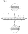
- the first moisture-proof protective film 10 has the area slightly larger than that of the phosphor plate 4 and the circumference of the film is extended out from the circumference of the phosphor plate 4 in a situation of that the film substantially not adhering with the stimulable phosphor layer 3 of the phosphor plate 4.
- the situation that "the first moisture-proof film 10 substantially not adhering with the stimulable phosphor layer 3" is a situation in which the moisture-proof protective film 10 is not optically unified with the stimulable phosphor layer 3, in concrete, a situation in which the adhering area of the first moisture-proof protective film 10 with the stimulable phosphor layer 3 is not more than 10% of the area of the surface of the stimulable phosphor layer 3 (the surface facing to the first moisture-proof protective film 10).
- the second layer 22 is an aluminum layer laminated on the first layer 21 as shown in Fig.1.
- the second layer 22 raises the anti-moisture ability of the second moisture-proof protective film 20.
- the second layer 22 may be omitted.
- Usual materials for protective layer such as cellulose acetate, cellulose nitrate, poly(methyl methacrylate), poly(vinyl butyral), poly(vinyl formal), polycarbonate, polyester, poly(ethylene terephthalate), polyethylene, poly(vinylidene chloride), nylon, polytetrafluoroethylene, polytrifluorochloroethylen, tetrafluoroethylenehexafluoroethylen copolymer, vinylidene chloride-vinyl chloride copolymer and vinylidene chloride-acrylonitrile copolymer are employable for the protective layer.
- a transparent glass plate can be also employed for the protective layer.
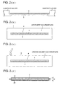
- An aluminum slit was arranged between the vapor source and the substrate so that the incident angle of the vapor of the stimulable phosphor with the normal line of the light reflection surface of the substrate was 30°. Thereafter, the vapor deposition was performed while the substrate was moved in the surface direction to form a layer of columnar crystal of the stimulable phosphor having a thickness of 300 ⁇ m on the light reflection layer of each of the substrates. Thus thirteen phosphor plates were prepared.
Landscapes
- Chemical & Material Sciences (AREA)
- Engineering & Computer Science (AREA)
- Physics & Mathematics (AREA)
- General Engineering & Computer Science (AREA)
- High Energy & Nuclear Physics (AREA)
- Inorganic Chemistry (AREA)
- Materials Engineering (AREA)
- Organic Chemistry (AREA)
- Conversion Of X-Rays Into Visible Images (AREA)
Applications Claiming Priority (2)
| Application Number | Priority Date | Filing Date | Title |
|---|---|---|---|
| JP2004262363A JP2006078324A (ja) | 2004-09-09 | 2004-09-09 | 放射線画像変換パネルの製造方法 |
| JP2004266876A JP2006084213A (ja) | 2004-09-14 | 2004-09-14 | 放射線画像変換パネルの製造方法 |
Publications (1)
| Publication Number | Publication Date |
|---|---|
| EP1635358A2 true EP1635358A2 (de) | 2006-03-15 |
Family
ID=35583514
Family Applications (1)
| Application Number | Title | Priority Date | Filing Date |
|---|---|---|---|
| EP05255386A Withdrawn EP1635358A2 (de) | 2004-09-09 | 2005-09-02 | Methode zur Herstellung eines Strahlungsbildwandlers |
Country Status (2)
| Country | Link |
|---|---|
| US (1) | US20060049370A1 (de) |
| EP (1) | EP1635358A2 (de) |
Families Citing this family (5)
| Publication number | Priority date | Publication date | Assignee | Title |
|---|---|---|---|---|
| KR20060081015A (ko) * | 2005-01-06 | 2006-07-12 | 삼성에스디아이 주식회사 | 진공 증착기 |
| WO2007060827A1 (ja) * | 2005-11-22 | 2007-05-31 | Konica Minolta Medical & Graphic, Inc. | 蛍光体プレートの製造方法及び蛍光体プレート |
| EP2133449B1 (de) * | 2007-02-07 | 2013-09-11 | Sakai Chemical Industry Co., Ltd. | Iodid-einkristall, verfahren zur herstellung des iodid-einkristalls und szintillator mit dem iodid-einkristall |
| EP2067841A1 (de) | 2007-12-06 | 2009-06-10 | Agfa HealthCare NV | Röntgenbildschirm oder -tafel mit photostimulierbarem Leuchtstoff |
| JP6217187B2 (ja) * | 2013-07-03 | 2017-10-25 | ソニー株式会社 | 発光装置および表示装置 |
Family Cites Families (15)
| Publication number | Priority date | Publication date | Assignee | Title |
|---|---|---|---|---|
| US4947046A (en) * | 1988-05-27 | 1990-08-07 | Konica Corporation | Method for preparation of radiographic image conversion panel and radiographic image conversion panel thereby |
| JP2001064645A (ja) * | 1999-09-01 | 2001-03-13 | Fuji Photo Film Co Ltd | 希土類賦活弗化ハロゲン化バリウム系蛍光体の製造装置、および製造方法 |
| US6815092B2 (en) * | 2001-12-05 | 2004-11-09 | Agfa-Gevaert | Radiation image storage panel |
| JP2003248097A (ja) * | 2002-02-25 | 2003-09-05 | Konica Corp | 放射線画像変換パネル及び放射線画像変換パネルの製造方法 |
| US7026631B2 (en) * | 2002-05-31 | 2006-04-11 | Konica Corporation | Radiation image conversion panel and preparation method thereof |
| JP2004205460A (ja) * | 2002-12-26 | 2004-07-22 | Konica Minolta Holdings Inc | 放射線画像変換パネル及び放射線画像変換パネルの製造方法 |
| US20040241395A1 (en) * | 2003-05-29 | 2004-12-02 | 3M Innovative Properties Company | Method of modifying a surface of a substrate and articles therefrom |
| JP2005083792A (ja) * | 2003-09-05 | 2005-03-31 | Konica Minolta Medical & Graphic Inc | 放射線画像変換パネル及びその製造方法 |
| JP2005091222A (ja) * | 2003-09-18 | 2005-04-07 | Fuji Photo Film Co Ltd | 放射線像変換パネルおよびその製造方法 |
| EP1523014A3 (de) * | 2003-10-10 | 2008-02-13 | Konica Minolta Medical & Graphic, Inc. | Strahlungsbildwandler und Verfahren zu seiner Herstellung |
| EP1526554A2 (de) * | 2003-10-23 | 2005-04-27 | Konica Minolta Medical & Graphic, Inc. | Strahlungsbildwandler |
| EP1533816A3 (de) * | 2003-11-18 | 2008-02-13 | Konica Minolta Medical & Graphic, Inc. | Strahlungsbildwandler und Verfahren zu seiner Herstellung |
| US7375349B2 (en) * | 2003-11-19 | 2008-05-20 | Fujifilm Corporation | Radiation-image conversion panel and process of producing the same |
| JP2005227169A (ja) * | 2004-02-13 | 2005-08-25 | Konica Minolta Medical & Graphic Inc | 放射線画像変換パネル |
| EP1605472A1 (de) * | 2004-06-10 | 2005-12-14 | Konica Minolta Medical & Graphic, Inc. | Strahlungsbildwandler |
-
2005
- 2005-08-30 US US11/215,245 patent/US20060049370A1/en not_active Abandoned
- 2005-09-02 EP EP05255386A patent/EP1635358A2/de not_active Withdrawn
Also Published As
| Publication number | Publication date |
|---|---|
| US20060049370A1 (en) | 2006-03-09 |
Similar Documents
| Publication | Publication Date | Title |
|---|---|---|
| JP2003248097A (ja) | 放射線画像変換パネル及び放射線画像変換パネルの製造方法 | |
| US7605380B2 (en) | Radiation image conversion panel | |
| US7199381B2 (en) | Radiation image conversion panel | |
| EP1635358A2 (de) | Methode zur Herstellung eines Strahlungsbildwandlers | |
| US20040183029A1 (en) | Radiographic image conversion panel | |
| JP4665968B2 (ja) | 放射線画像変換パネル | |
| US8063387B2 (en) | Radiation image conversion panel | |
| JP4378959B2 (ja) | 放射線画像変換パネルの製造方法 | |
| JP3538781B2 (ja) | アルカリハライド蛍光体、その蛍光体を用いた放射線画像変換パネルおよびその放射線画像変換パネルを用いた放射線画像変換方法 | |
| JP2005083792A (ja) | 放射線画像変換パネル及びその製造方法 | |
| JP2005164576A (ja) | 放射線画像変換パネル | |
| JP2006125932A (ja) | 放射線画像変換パネルの製造方法 | |
| JP2006084213A (ja) | 放射線画像変換パネルの製造方法 | |
| JP3228527B2 (ja) | 放射線画像変換パネルの製造方法 | |
| JP4259035B2 (ja) | 放射線画像変換パネル及び放射線画像変換パネルの製造方法 | |
| JP4492288B2 (ja) | 放射線画像変換パネル | |
| JP2004205354A (ja) | 放射線画像変換パネルの製造方法及び放射線画像変換パネル | |
| EP1526554A2 (de) | Strahlungsbildwandler | |
| JP2006078324A (ja) | 放射線画像変換パネルの製造方法 | |
| JP3307407B2 (ja) | 放射線画像変換パネルの製造方法 | |
| JP2005106544A (ja) | 放射線像変換パネル及び放射線像変換パネルの製造方法 | |
| JP2006125854A (ja) | 放射線画像変換パネル及びその製造方法 | |
| JP2007161952A (ja) | 放射線画像変換パネルとその製造方法 | |
| JP2007024817A (ja) | 放射線画像変換パネル及びその製造方法 | |
| US20070075282A1 (en) | Radiation image storage panel and process for producing the same |
Legal Events
| Date | Code | Title | Description |
|---|---|---|---|
| PUAI | Public reference made under article 153(3) epc to a published international application that has entered the european phase |
Free format text: ORIGINAL CODE: 0009012 |
|
| AK | Designated contracting states |
Kind code of ref document: A2 Designated state(s): AT BE BG CH CY CZ DE DK EE ES FI FR GB GR HU IE IS IT LI LT LU LV MC NL PL PT RO SE SI SK TR |
|
| AX | Request for extension of the european patent |
Extension state: AL BA HR MK YU |
|
| RAP1 | Party data changed (applicant data changed or rights of an application transferred) |
Owner name: KONICA MINOLTA MEDICAL & GRAPHIC, INC. |
|
| STAA | Information on the status of an ep patent application or granted ep patent |
Free format text: STATUS: THE APPLICATION HAS BEEN WITHDRAWN |
|
| 18W | Application withdrawn |
Effective date: 20080418 |