EP1635367A1 - Interrupteur de charnière - Google Patents
Interrupteur de charnière Download PDFInfo
- Publication number
- EP1635367A1 EP1635367A1 EP05018628A EP05018628A EP1635367A1 EP 1635367 A1 EP1635367 A1 EP 1635367A1 EP 05018628 A EP05018628 A EP 05018628A EP 05018628 A EP05018628 A EP 05018628A EP 1635367 A1 EP1635367 A1 EP 1635367A1
- Authority
- EP
- European Patent Office
- Prior art keywords
- hinge
- worm
- switching
- shaft
- wing
- Prior art date
- Legal status (The legal status is an assumption and is not a legal conclusion. Google has not performed a legal analysis and makes no representation as to the accuracy of the status listed.)
- Granted
Links
- 230000037431 insertion Effects 0.000 claims 1
- 238000003780 insertion Methods 0.000 claims 1
- 230000005540 biological transmission Effects 0.000 description 2
- 238000006073 displacement reaction Methods 0.000 description 1
- 238000005461 lubrication Methods 0.000 description 1
- 238000010008 shearing Methods 0.000 description 1
Images


Classifications
-
- H—ELECTRICITY
- H01—ELECTRIC ELEMENTS
- H01H—ELECTRIC SWITCHES; RELAYS; SELECTORS; EMERGENCY PROTECTIVE DEVICES
- H01H3/00—Mechanisms for operating contacts
- H01H3/02—Operating parts, i.e. for operating driving mechanism by a mechanical force external to the switch
- H01H3/16—Operating parts, i.e. for operating driving mechanism by a mechanical force external to the switch adapted for actuation at a limit or other predetermined position in the path of a body, the relative movement of switch and body being primarily for a purpose other than the actuation of the switch, e.g. for a door switch, a limit switch, a floor-levelling switch of a lift
- H01H3/161—Operating parts, i.e. for operating driving mechanism by a mechanical force external to the switch adapted for actuation at a limit or other predetermined position in the path of a body, the relative movement of switch and body being primarily for a purpose other than the actuation of the switch, e.g. for a door switch, a limit switch, a floor-levelling switch of a lift for actuation by moving a closing member, e.g. door, cover or lid
- H01H3/162—Operating parts, i.e. for operating driving mechanism by a mechanical force external to the switch adapted for actuation at a limit or other predetermined position in the path of a body, the relative movement of switch and body being primarily for a purpose other than the actuation of the switch, e.g. for a door switch, a limit switch, a floor-levelling switch of a lift for actuation by moving a closing member, e.g. door, cover or lid associated with a hinge of the closing member
-
- E—FIXED CONSTRUCTIONS
- E05—LOCKS; KEYS; WINDOW OR DOOR FITTINGS; SAFES
- E05D—HINGES OR SUSPENSION DEVICES FOR DOORS, WINDOWS OR WINGS
- E05D11/00—Additional features or accessories of hinges
- E05D11/0081—Additional features or accessories of hinges for transmitting energy, e.g. electrical cable routing
Definitions
- the invention relates to a hinge switch, in particular for doors and flaps, comprising a first hinge wing with an actuatable via a plunger contact switch, a second hinge wing, which is pivotally connected to the first hinge wing, wherein a rotationally connected to the second hinge wing connected switching shaft is provided , which cooperates with the plunger and with respect to this and the first hinge wing is freely pivotable, wherein the relative position of the switching shaft to the second hinge wing defines a switching angle.
- a hinge switch of the type mentioned is known from EP-A-304 241.
- the switching angle is adjustable by turning the control shaft with a special key, for which purpose a the shift shaft clamping screw must be solved before, which is to be put on again after adjustment.
- the switching shaft is formed as a hinge wings connecting the bolt together.
- the hinge according to EP-A-0304241 is very maintenance-prone, as it can come by improper lubrication of the bolt with the steering knuckle to a setting between the shaft and the knuckle, which can lead to a shearing of the clamping screw, whereby the switching angle is adjusted ,
- GB-A-2 150 757 relates to a hinge switch having a first hinge wing and a second hinge wing which are hingedly connected to each other, wherein coaxial with a bolt connecting the hinge wings connecting elements are provided, consisting of a first switching contact and a second switching contact , Wherein a switching angle of the switching element via rotation of a switching contact by means of a transmission is adjustable.
- Another hinge switch is described in EP-B-1 239 496.
- This comprises a first, a lever operable via a switch receiving hinge wing, a second hinge wing and a shaft which is rotationally connected in the operating position with the second hinge wing and at its periphery has a running in the shaft axis switching groove, in which in a predetermined pivot position between the two hinge wings an operating pin connected to the lever is immersed, wherein the lever is parallel to the shaft longitudinal axis and with respect to this pivotable and loaded by a spring in the direction of the shaft and is in the range of a switching cam or switch pin of the switch.
- the hinge switch of the known type is characterized in that it is secured in a pre-assembly in which the actuating pin engages in the switching grooves against the first hinge wing against rotation and the second hinge wing against the shaft is freely pivoted, the shaft by a in one Inserted screw is screwed by a predetermined amount from the pre-assembly out to the operating position axially and wherein the shaft is provided with a knurled or otherwise structured annular zone, which in shifted in operating position shaft in a hinge hole of the second hinge wing to achieve the rotation between the second hinge wing and the shaft is pressed form-fitting manner.
- an adjustable hinge switch wherein the setting, if this is done once, due to the non-detachable connection, ie the positive fit of the shaft in the second hinge wing not is more solvable, so that, for example, readjustments or reuse of the hinge switch with different switching angles is not possible.
- the present invention the object of developing an adjustable hinge switch of the type mentioned above such that the switching angle of the shift shaft in a simple manner repeatedly as often as is adjustable.
- the object is u. a. achieved in that the switching angle is adjustable by turning the switching shaft by means of a self-locking gear designed as a worm gear, that the worm gear comprises a worm engaging in a worm wheel, wherein the worm is rotatable in a firmly connected to the second hinge wing screw housing, that the worm wheel coaxial to a bolt connecting the first and second hinge wings and that the shift shaft is fixedly connected to the worm wheel and arranged coaxially with the bolt.
- a self-locking gear designed as a worm gear
- the worm gear comprises a worm engaging in a worm wheel, wherein the worm is rotatable in a firmly connected to the second hinge wing screw housing, that the worm wheel coaxial to a bolt connecting the first and second hinge wings and that the shift shaft is fixedly connected to the worm wheel and arranged coaxially with the bolt.
- Self-locking is achieved by providing a teeth ratio in the range of 1:40.
- the self-locking gear is designed to be lockable.
- a closure such as contour stopper is introduced into the worm and / or the worm housing receiving the worm as hammered.
- the closure is connected to an adjustment key or molded onto it and, in particular after being inserted, can be separated from the adjustment key, in particular bent off.
- the worm wheel extends in a direction perpendicular to the longitudinal axis of the rotating belt extending plane, wherein the emanating from the Scheckenrad Switching shaft with switching cam extends coaxially with the bolt connecting the hinge wings.
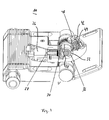
- Fig. 1 shows a perspective view of a hinge switch 10 with a first hinge wing 12 with two outer hinge eyes 14, 16 and a second hinge wing 18 with inner hinge eyes 20, 22, via the hinge eyes 14, 16, 20, 22 articulated by a bolt 24 connected to each other.
- the switching shaft 32 is adjustable relative to the second hinge wing 18 for setting a switching angle by means of a self-locking gear 34.
- a surface 36 of the switching shaft is a switching curve formed, which abuts in response to an angular position between the hinge wings 12, 18 at least temporarily on an inner surface 38 of a substantially crescent-shaped plunger element 30.1.
- the self-locking gear 34 comprises a worm wheel 40 which is adjustable via a worm 44 rotatably mounted in a worm housing 42.
- the screw housing 42 is fixedly connected to the second hinge wing 18.
- the worm gear 34 is designed to be self-locking, which is achieved by means of a tooth ratio of, for example 1/40.
- the rotation can be carried out by means of an adjustment key 46, which has a special profile 48 engaging in the worm 44 at the front, in order to rotate the worm 44.
- a closure element 50 in an end-side Publ tion 52 of the screw housing 42 is inserted as taken, whereby the setting or switching angle is manipulation-proof.
- the closure element 50 which is preferably designed as a contour plug, is connected to the adjustment key 46 and is separated after being knocked by the adjustment key 46 by kinking.
- Fig. 2 shows a perspective view of the hinge switch 10, wherein the second hinge wing 18 is rotated by approximately 20 ° to the right. Also in this state are plunger 30 and shift shaft 36 in the idle state.
- Fig. 3 shows a perspective view of the hinge switch 10 in a position in which the plunger 30 is actuated and acts on the actuating element 28 of the switching contact 26.
- the surface 36 of the switching shaft 32 abuts the inner side 38 of the plunger 30, whereby a displacement of the plunger 30 is effected.
- the plunger 30 remains actuated in the, ie pressed position.
- 3 likewise shows the screw housing 42 closed by means of the closure 48 for tamper-proof closing of the screw 44.
- Fig. 4 shows the hinge switch 10 in an assembled state, wherein the first hinge wing 12, for example, on a door frame 52 and the second hinge wing is mounted on a door frame 54.
Landscapes
- Engineering & Computer Science (AREA)
- Computer Security & Cryptography (AREA)
- Hinges (AREA)
- Specific Sealing Or Ventilating Devices For Doors And Windows (AREA)
Applications Claiming Priority (1)
| Application Number | Priority Date | Filing Date | Title |
|---|---|---|---|
| DE200410041723 DE102004041723B3 (de) | 2004-08-28 | 2004-08-28 | Scharnierschalter |
Publications (2)
| Publication Number | Publication Date |
|---|---|
| EP1635367A1 true EP1635367A1 (fr) | 2006-03-15 |
| EP1635367B1 EP1635367B1 (fr) | 2007-12-19 |
Family
ID=35276501
Family Applications (1)
| Application Number | Title | Priority Date | Filing Date |
|---|---|---|---|
| EP05018628A Ceased EP1635367B1 (fr) | 2004-08-28 | 2005-08-26 | Interrupteur de charnière |
Country Status (2)
| Country | Link |
|---|---|
| EP (1) | EP1635367B1 (fr) |
| DE (2) | DE102004041723B3 (fr) |
Cited By (2)
| Publication number | Priority date | Publication date | Assignee | Title |
|---|---|---|---|---|
| CN102312632A (zh) * | 2010-07-06 | 2012-01-11 | S-紧固件股份有限公司 | 具有张力可调节的螺旋扭力弹簧的铰接装置 |
| US20150218864A1 (en) * | 2014-02-05 | 2015-08-06 | Zero Zone, Inc. | Door closer mechanism for display case |
Families Citing this family (1)
| Publication number | Priority date | Publication date | Assignee | Title |
|---|---|---|---|---|
| DE102005046082A1 (de) * | 2005-09-26 | 2007-04-12 | Bernstein Ag | Schaltscharnier |
Citations (4)
| Publication number | Priority date | Publication date | Assignee | Title |
|---|---|---|---|---|
| US4284861A (en) * | 1980-01-09 | 1981-08-18 | Hager Hinge Company | Switch hinge |
| GB2150757A (en) | 1983-11-21 | 1985-07-03 | Cheng Chao An | Combined hinge and electric switch assembly |
| EP0304241A2 (fr) | 1987-08-15 | 1989-02-22 | John Leon Brown | Dispositif interrupteur de charnière |
| EP1239496B1 (fr) | 2001-03-06 | 2003-04-09 | Bernstein AG | Charnière avec interrupteur |
-
2004
- 2004-08-28 DE DE200410041723 patent/DE102004041723B3/de not_active Expired - Fee Related
-
2005
- 2005-08-26 DE DE200550002273 patent/DE502005002273D1/de not_active Expired - Lifetime
- 2005-08-26 EP EP05018628A patent/EP1635367B1/fr not_active Ceased
Patent Citations (4)
| Publication number | Priority date | Publication date | Assignee | Title |
|---|---|---|---|---|
| US4284861A (en) * | 1980-01-09 | 1981-08-18 | Hager Hinge Company | Switch hinge |
| GB2150757A (en) | 1983-11-21 | 1985-07-03 | Cheng Chao An | Combined hinge and electric switch assembly |
| EP0304241A2 (fr) | 1987-08-15 | 1989-02-22 | John Leon Brown | Dispositif interrupteur de charnière |
| EP1239496B1 (fr) | 2001-03-06 | 2003-04-09 | Bernstein AG | Charnière avec interrupteur |
Cited By (6)
| Publication number | Priority date | Publication date | Assignee | Title |
|---|---|---|---|---|
| CN102312632A (zh) * | 2010-07-06 | 2012-01-11 | S-紧固件股份有限公司 | 具有张力可调节的螺旋扭力弹簧的铰接装置 |
| US20120005861A1 (en) * | 2010-07-06 | 2012-01-12 | S-Fasteners Gmbh | Hinge with tension-adjustable spiral torsion spring |
| US8245353B2 (en) * | 2010-07-06 | 2012-08-21 | S-Fasteners Gmbh | Hinge with tension-adjustable spiral torsion spring |
| US20150218864A1 (en) * | 2014-02-05 | 2015-08-06 | Zero Zone, Inc. | Door closer mechanism for display case |
| US9394736B2 (en) * | 2014-02-05 | 2016-07-19 | Zero Zone, Inc. | Door closer mechanism for display case |
| US9974398B2 (en) | 2014-02-05 | 2018-05-22 | Zero Zone, Inc. | Door closer mechanism for display case |
Also Published As
| Publication number | Publication date |
|---|---|
| EP1635367B1 (fr) | 2007-12-19 |
| DE102004041723B3 (de) | 2006-04-06 |
| DE502005002273D1 (de) | 2008-01-31 |
Similar Documents
| Publication | Publication Date | Title |
|---|---|---|
| DE10013726C2 (de) | Klappenscharnier | |
| DE19823188C2 (de) | Kraftfahrzeugtürverschluß | |
| EP2107189B1 (fr) | Armature pour fenêtres ou portes | |
| EP1262616B1 (fr) | Dispositif de verrouillage | |
| DE2916559C2 (de) | Lenkschloß | |
| EP1239496A1 (fr) | Charnière avec interrupteur | |
| EP1518985B1 (fr) | Mécanisme d'engrenage, en particulier mécanisme d'engrenage encastré pour fenêtre ou similaire | |
| WO2005108752A1 (fr) | Variateur d'arbre a cames hydraulique et procede de montage | |
| DE102009002478B4 (de) | Ver- und Feststellvorrichtung eines Verstellbeschlages | |
| EP2397627B1 (fr) | Dispositif de couplage et de découplage d'une poignée extérieure de porte | |
| DE10331868B4 (de) | Rastgelenkverbindung | |
| EP1635367B1 (fr) | Interrupteur de charnière | |
| EP1279783B1 (fr) | Dispositif de verrouillage | |
| EP1722050B1 (fr) | Serrure à verrou rotatif | |
| DE102008061691A1 (de) | Beschlaganordnung für einen Sitz, insbesondere Fahrzeugsitz sowie Verfahren zur Montage einer solchen Beschlaganordnung | |
| DE112004001173B4 (de) | Gelenkbeschlag für Kraftfahrzeugsitze mit mindestens zwei Sperrarmen | |
| DE19526660B4 (de) | Elektromechanisches Schloß | |
| DE102006032681A1 (de) | Rastronde mit Mehrkant und Feder | |
| DE4418082C1 (de) | Mehrteiliges Scharnier | |
| DE4132567C2 (de) | Langsam agierende Drehachsenvorrichtung | |
| EP4263981B1 (fr) | Poignée d'actionnement pour fenêtres et portes sans rosette | |
| EP0940549B1 (fr) | Pièce d'assemblage d'angle pour relier par soudage deux profilés creux | |
| DE19963702A1 (de) | Feststellvorrichtung für zwei gegeneinander schwenkbare Bauteile | |
| DE202007016708U1 (de) | Band für Türen, Fenster o.dgl. | |
| DE19717117A1 (de) | Drehlager |
Legal Events
| Date | Code | Title | Description |
|---|---|---|---|
| PUAI | Public reference made under article 153(3) epc to a published international application that has entered the european phase |
Free format text: ORIGINAL CODE: 0009012 |
|
| AK | Designated contracting states |
Kind code of ref document: A1 Designated state(s): AT BE BG CH CY CZ DE DK EE ES FI FR GB GR HU IE IS IT LI LT LU LV MC NL PL PT RO SE SI SK TR |
|
| AX | Request for extension of the european patent |
Extension state: AL BA HR MK YU |
|
| 17P | Request for examination filed |
Effective date: 20060118 |
|
| AKX | Designation fees paid |
Designated state(s): BG FR GB |
|
| RBV | Designated contracting states (corrected) |
Designated state(s): DE FR GB |
|
| REG | Reference to a national code |
Ref country code: DE Ref legal event code: 8566 |
|
| GRAP | Despatch of communication of intention to grant a patent |
Free format text: ORIGINAL CODE: EPIDOSNIGR1 |
|
| GRAS | Grant fee paid |
Free format text: ORIGINAL CODE: EPIDOSNIGR3 |
|
| GRAA | (expected) grant |
Free format text: ORIGINAL CODE: 0009210 |
|
| AK | Designated contracting states |
Kind code of ref document: B1 Designated state(s): DE FR GB |
|
| REG | Reference to a national code |
Ref country code: GB Ref legal event code: FG4D Free format text: NOT ENGLISH |
|
| REF | Corresponds to: |
Ref document number: 502005002273 Country of ref document: DE Date of ref document: 20080131 Kind code of ref document: P |
|
| ET | Fr: translation filed | ||
| PLBE | No opposition filed within time limit |
Free format text: ORIGINAL CODE: 0009261 |
|
| STAA | Information on the status of an ep patent application or granted ep patent |
Free format text: STATUS: NO OPPOSITION FILED WITHIN TIME LIMIT |
|
| 26N | No opposition filed |
Effective date: 20080922 |
|
| REG | Reference to a national code |
Ref country code: FR Ref legal event code: PLFP Year of fee payment: 12 |
|
| REG | Reference to a national code |
Ref country code: FR Ref legal event code: PLFP Year of fee payment: 13 |
|
| REG | Reference to a national code |
Ref country code: FR Ref legal event code: PLFP Year of fee payment: 14 |
|
| PGFP | Annual fee paid to national office [announced via postgrant information from national office to epo] |
Ref country code: FR Payment date: 20210819 Year of fee payment: 17 |
|
| PGFP | Annual fee paid to national office [announced via postgrant information from national office to epo] |
Ref country code: DE Payment date: 20210810 Year of fee payment: 17 Ref country code: GB Payment date: 20210820 Year of fee payment: 17 |
|
| REG | Reference to a national code |
Ref country code: DE Ref legal event code: R119 Ref document number: 502005002273 Country of ref document: DE |
|
| GBPC | Gb: european patent ceased through non-payment of renewal fee |
Effective date: 20220826 |
|
| PG25 | Lapsed in a contracting state [announced via postgrant information from national office to epo] |
Ref country code: FR Free format text: LAPSE BECAUSE OF NON-PAYMENT OF DUE FEES Effective date: 20220831 Ref country code: DE Free format text: LAPSE BECAUSE OF NON-PAYMENT OF DUE FEES Effective date: 20230301 |
|
| PG25 | Lapsed in a contracting state [announced via postgrant information from national office to epo] |
Ref country code: GB Free format text: LAPSE BECAUSE OF NON-PAYMENT OF DUE FEES Effective date: 20220826 |