EP1635483A1 - Procede et dispositif de reglage de la puissance d'emission - Google Patents
Procede et dispositif de reglage de la puissance d'emission Download PDFInfo
- Publication number
- EP1635483A1 EP1635483A1 EP03817196A EP03817196A EP1635483A1 EP 1635483 A1 EP1635483 A1 EP 1635483A1 EP 03817196 A EP03817196 A EP 03817196A EP 03817196 A EP03817196 A EP 03817196A EP 1635483 A1 EP1635483 A1 EP 1635483A1
- Authority
- EP
- European Patent Office
- Prior art keywords
- sir
- target
- error rate
- bler
- updating
- Prior art date
- Legal status (The legal status is an assumption and is not a legal conclusion. Google has not performed a legal analysis and makes no representation as to the accuracy of the status listed.)
- Granted
Links
Images





Classifications
-
- H—ELECTRICITY
- H04—ELECTRIC COMMUNICATION TECHNIQUE
- H04W—WIRELESS COMMUNICATION NETWORKS
- H04W52/00—Power management, e.g. Transmission Power Control [TPC] or power classes
- H04W52/04—Transmission power control [TPC]
- H04W52/18—TPC being performed according to specific parameters
- H04W52/24—TPC being performed according to specific parameters using SIR [Signal to Interference Ratio] or other wireless path parameters
- H04W52/241—TPC being performed according to specific parameters using SIR [Signal to Interference Ratio] or other wireless path parameters taking into account channel quality metrics, e.g. SIR, SNR, CIR or Eb/lo
-
- H—ELECTRICITY
- H04—ELECTRIC COMMUNICATION TECHNIQUE
- H04W—WIRELESS COMMUNICATION NETWORKS
- H04W52/00—Power management, e.g. Transmission Power Control [TPC] or power classes
- H04W52/04—Transmission power control [TPC]
- H04W52/06—TPC algorithms
- H04W52/12—Outer and inner loops
-
- H—ELECTRICITY
- H04—ELECTRIC COMMUNICATION TECHNIQUE
- H04B—TRANSMISSION
- H04B1/00—Details of transmission systems, not covered by a single one of groups H04B3/00 - H04B13/00; Details of transmission systems not characterised by the medium used for transmission
- H04B1/69—Spread spectrum techniques
- H04B1/707—Spread spectrum techniques using direct sequence modulation
Definitions
- This invention relates to a transmission power control method and apparatus. More particularly, the invention relates to a transmission power control method and apparatus in a W-CDMA communication system, etc., for comparing the error rate of receive data and a target error rate on the receiving side, controlling a target SIR which is a target ratio of signal wave to interference wave and causing the transmitting side to control transmission power in such a manner that measured SIR will agree with the target SIR.
- a target SIR which is a target ratio of signal wave to interference wave
- a receive signal In order to distinguish a channel by a spreading code in W-CDMA mobile communications, multiple channels can share a single frequency band.
- a receive signal In an actual mobile communications environment, however, a receive signal is susceptible to interference from its own channel and from other channels owing to delayed waves ascribable to multipath fading and radio waves from other cells, and this interference has an adverse influence upon channel separation. Further, the amount of interference sustained by a receive signal varies with time owing to momentary fluctuations in reception power ascribable to multipath fading and changes in the number of users communicating simultaneously. In an environment in which a receive signal is susceptible to noise that varies with time in this fashion, it is difficult for the quality of a receive signal in a mobile station linked to a base station to be maintained at a desired quality in a stable manner.
- SIR signal-to-interference ratio
- Fig. 19 is a diagram useful in describing inner-loop transmission power control. Here only one channel is illustrated.
- a spread-spectrum modulator 1a of a base station 1 spread-spectrum modulates transmit data using a spreading code conforming to a specified channel.
- the spread-spectrum modulated signal is subjected to processing such as orthogonal modulation and frequency conversion and the resultant signal is input to a power amplifier 1b, which amplifies this signal and transmits the amplified signal toward a mobile station 2 from an antenna.
- a despreading unit 2a in the receiver of the mobile station applies despread processing to the receive signal and a demodulator 2b demodulates the receive data.
- a SIR measurement unit 2c measures the power ratio between the receive signal and an interference signal and a comparator 2d compares target SIR and measured SIR. If the measured SIR is greater than the target SIR, the comparator creates a command that lowers the transmission power by TPC (Transmission Power Control) bits. If the measured SIR is less than the target SIR, the comparator creates a command that raises the transmission power by the TPC bits.
- the target SIR is a SIR value necessary to obtain, e.g., 10 -3 (error occurrence at a rate of once every 1000 times). This value is input to the comparator 2d from a target-SIR setting unit 2e.
- a spread-spectrum modulator 2f spread-spectrum modulates the transmit data and TPC bits.
- the mobile station 2 subjects the signal to processing such as a DA conversion, orthogonal modulation, frequency conversion and power amplification and transmits the resultant signal toward the base station 1 from an antenna.
- a despreading unit 1c on the side of the base station applies despread processing to the signal received from the mobile station 2, and a demodulator 1d demodulates the receive data and TPC bits and controls the transmission power of the power amplifier 1b in accordance with a command specified by the TPC bits.
- Fig. 20 is a diagram showing the structure of a DPCH (Dedicated Physical Channel) frame of an uplink standardized by the 3 rd Generation Partnership Project (referred to as "3GPP" below).
- a DPDCH channel Dedicated Physical Data Channel
- a DPCCH channel Dedicated Physical Control Channel
- One frame of the uplink has a duration of 10 ms and is composed of 15 slots (slot #0 to slot #14).
- the DPDCH channel is mapped to an orthogonal I channel of QPSK modulation, and the DPCCH channel is mapped to an orthogonal Q channel of QPSK modulation.
- Each slot of the DPDCH channel consists of n bits, and n varies in accordance with the symbol rate.
- Each slot of the DPCCH control channel that transmits the control data consists of ten bits, has a fixed symbol rate of 15 ksps and transmits a pilot PILOT, transmission power control data TPC, a transport format combination indicator TFCI and feedback information FBI.
- the SIR that is necessary to obtain a desired quality (the block error rate, or BLER) is not constant.
- the BLER is the ratio between the total number of transport blocks (TrBk) and number of TrBks for which a CRC error has occurred over a fixed period of time.
- Fig. 21 is a block diagram of well-known outer-loop control. This scheme is such that a signal that has been transmitted from a base station 3 is demodulated by a demodulator 4a and then subsequently decoded by an error-correction decoder 4b. Thenceforth, in a CRC detector 4c, the signal is split into transport blocks TrBk, after which CRC error detection is carried out on a per-TrBk basis. The result of error detection of each transport block TrBk is sent to a target-SIR controller 4d.
- encoding is performed on the transmitting side in the manner illustrated in Fig. 22. Specifically, if a plurality (N) of transport blocks TrBk exist in a unit transmission time (Transmission Time Interval, or TTI), a CRC add-on circuit on the transmitting side generates a CRC (Cyclic Redundancy Code) error detection code for every transport block TrBk and adds this onto the transmit data.
- An encoder joins the N-number of transport blocks TrBk having the attached CRCs and encodes the blocks by error correcting coding such as convolutional coding or turbo coding.
- the error correcting decoder 4b subjects the receive data to error-correction decoding processing and inputs the result of decoding to the CRC detector 4c, and the CRC detector 4c performs CRC error detection for every transport block TrBk constituting the result of decoding and inputs the results of error detection to the target-SIR controller 4d.
- a host application specifies the required BLER of each service depending upon the service type of the DCH, such as voice, packet or unrestricted digital.
- BLER quality represent the required BLER
- Tmax represent the number of transport blocks TrBk for which BLER is measured
- Sinc (dB) represent an update quantity for raising the target SIR in a case where the measured BLER is inferior to the required BLER
- Sdec (dB) represent an update quantity for lowering the target SIR in a case where the measured BLER is superior to the required BLER.
- the target SIR is updated by Sinc. If CRC OK holds throughout, the target SIR is updated by Sdec. When this is observed in total, the target SIR settles stabilizes at a fixed level. This is the fundamental concept of outer-loop control.
- BLER measurement is performed with regard to Tmax-number of TrBks. If CRC OK is obtained for all TrBks, the target SIR is updated by Sdec. If there is even one CRC NG (CRC error), then the target SIR is updated by Sinc.
- the values of Sinc, Sdec and Tmax are values uniquely decided by the required BLER of each service. Accordingly, in a case where a plurality of transport channels (abbreviated to "TrCH” below) have been mapped to a single physical channel (abbreviated to "PhCH” below), then values of Sinc, Sdec and Tmax will exist for each TrCH.
- TrCH transport channels
- PhCH physical channel
- T2 interval 500 ms stipulation. It is also necessary to pull the DPCH SIR value, which has been decided by initial pull-in, into the range -3 dB to +1 dB within 500 ms following the T1 interval (this is referred to as the "steady state").
- the period at which the target SIR is updated is uniquely decided after Tmax-number of BLER measurements. Consequently, if this measurement period does not fall within the T1 time period, the target SIR will not be updated from the initial target SIR in a period greater than the T1 time period, and hence there is the possibility that initial pull-in cannot be achieved as specified in Standard 1.
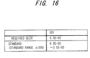
- 3GPP TS25.101 recites a standard to the effect that measured BLER fall within a range of ⁇ 30% of the required BLER.
- the updating period of the target SIR and the updated value of the target SIR are decided uniquely for every required BLER specified on a pre-service basis. During the connection of a certain service, therefore, these values are fixed.
- the antenna characteristic the characteristic of the receiver that down-converts a highfrequency signal to a baseband signal
- the characteristic of the demodulator that applies despread processing to the baseband signal the characteristics of the various components of the decoder that applies an error correction to the symbol signal that has been despread
- the characteristics of a certain apparatus will differ from those of an apparatus having other specifications.
- the BLER vs. SCR characteristic will differ depending upon the apparatus specifications, etc.
- reception sensitivity varies depending upon whether the apparatus has whip antenna in terms of the antenna configuration, or the decoding characteristic varies owing to a disparity in soft-decision bit width in the error correcting unit, and therefore the BLER vs. SCR characteristic differs depending upon whether the apparatus has a whip antenna or because of the disparity in soft-decision bit width. Therefore, with the conventional method of controlling target SIR based upon the prescribed BLER vs. SCR characteristic, a situation arises in which the required BLER cannot be satisfied depending upon the apparatus.
- This 3GPP standard applies weighting to a rate-matching attribute parameter (RM) to satisfy the required quality of each TrCH and makes the characteristic of a TrCH having good quality and the characteristic of a TrCH having poor quality approach each other.
- RM rate-matching attribute parameter
- the prior art in which the parameter ⁇ decided uniquely for the service of each TrCH is adopted as the target SIR with respect to the required BLER is such that in a case where a data transmission is performed on a low-quality TrCH alone, the required BLER of this TrCH can no longer be satisfied. That is, if data is transmitted solely by the low-quality TrCH2, ⁇ B will hold and the required BLER of the low-quality TrCH can no longer be satisfied. It should be noted that since ⁇ >B holds, the required BLER can be satisfied with regard to TrCH1.
- TrCH 3 the standard (Standard 3) to the effect that the measured BLER fall within the range of ⁇ 30% of the required BLER is no longer satisfied.
- the standard range of this TrCH is 3.5 ⁇ 10 -3 to 6.5 ⁇ 10 -3
- the standard range of this TrCH is 3.5 ⁇ 10 -2 to 6.5 ⁇ 10 -2 .
- the ranges of the two standards do not overlap. In such case, Standard 3 can no longer be satisfied.
- control entails detecting receive error rate of a receive signal; comparing the receive error rate and a target receive error rate set in advance; correcting, based upon the result of the comparison, a target reception signal power vs. interference power ratio (SIR) to serve as a target or a target reception power value to serve as a target; and controlling transmission power on the transmitting side based upon the corrected SIR or target reception power value.
- SIR target reception signal power vs. interference power ratio
- Patent Reference 2 WO 97/50197.
- This prior art measures the error rate of a receive signal and changes the target SIR based upon the error rate.
- the error rate of the receive signal is acquired by detecting a frame unit using a CRC signal or by detecting error of a known pilot signal that has been inserted at a fixed period.
- these examples of the prior art cannot control the target SIR so as to satisfy the required BLER of apparatuses having different characteristics. Further, these examples of the prior art cannot update the target SIR and control the updating period in accordance with the propagation environment even if the propagation environment changes. The end result is that the required BLER cannot be satisfied when the propagation environment fluctuates. Furthermore, these examples of the prior art are such that even in a case where a sole TrCH is used and in a case where a plurality of TrCHs are multiplexed, the target SIR cannot be updated in such a manner that the required BLER can be satisfied. In addition, the target SIR also cannot be controlled so as to satisfy the standards.
- An object of the present invention is to update target SIR and control the updating period of target SIR in accordance with the propagation environment even if the propagation environment changes, thereby making it possible to satisfy the required BLER at the time of fluctuation in propagation environment.
- Another object of the present invention is to set a target SIR in such a manner that the required BLER can be satisfied irrespective of the target-SIR updating period.
- a further object of the present invention is to enable updating of target SIR in such a manner that the required BLER can be satisfied even in a case where a sole TrCH is used and even in a case where a plurality of TrCHs are multiplexed.
- Still another object of the present invention is to control target SIR so as to satisfy standards.
- Another object of the present invention is to so arrange it that the required BLER of at least one TrCH can be satisfied if Standard 3 cannot be satisfied simultaneously for each TrCH.
- the present invention is a transmission power control method for controlling a target SIR which is a target of signal to interference upon comparing error rate and target error rate of receive data on a receiving side, and causing transmission power control to be performed on a transmitting side so that measured SIR will agree with target SIR.
- the method includes previously measuring and storing a correspondence characteristic between error rate (BLER) and SIR; finding a first SIR with respect to a target error rate and a second SIR with respect to a measured error rate from the characteristic; and updating the target SIR by increasing or decreasing the target SIR by the difference between the first SIR and the second SIR.
- BLER error rate
- a target SIR that satisfies the required BLER can be set irrespective of the apparatus characteristic by measuring the BLER vs. SIR characteristic.
- the characteristic is stored beforehand in accordance with the service quality and the target SIR is updated using the characteristic that conforms to the service quality. If this arrangement is adopted, a required BLER can be satisfied for any service.
- the method includes previously measuring and storing a correspondence characteristic between error rate and SIR on a per-transport-channel basis in a case where a plurality of transport channels are multiplexed and transmitted; finding, from the characteristic, a first SIR with respect to a target error rate and a second SIR with respect to a measured error rate in each transport channel in a case where a plurality of transport channels are multiplexed and transmitted; and updating the target SIR by increasing or decreasing the target SIR by the difference between the first SIR and the second SIR on a per-transport-channel basis.
- a target SIR that satisfies the required BLER can be set even at the time of multiplexed transmission by measuring the BLER vs. SIR characteristic at the time of multiplexed transmission of a plurality of TrCHs.
- the second mode is such that in a case where required error-rate ranges on transport channels do not overlap, the target SIR is updated so as to satisfy the required error rate of the transport channel that requires the highest quality. If this arrangement is adopted, the required BLER can be satisfied on all TrCHs even if the required error-rate ranges do not overlap.
- the second mode is such that in a case where prescribed error-rate ranges on transport channels do not overlap, the target SIR is updated so as to satisfy the prescribed error rate value of the transport channel for which the lowest quality is required. If this arrangement is adopted, the required BLER can be satisfied on at least one TrCH even in a case where required error-rate ranges do not overlap. Moreover, the target SIR can be set to a low level on another TrCH and downlink power from another base station can be controlled so as to be minimized.
- the method includes updating the target SIR at a first period t1 in order to pull error rate into a stipulated range of required error rates within a first stipulated time T1; and updating the target SIR at a second period t2, which is longer than the first period, after pull-in in order to make the error rate converge to within the stipulated range within a second stipulated time T2.
- the first period t1 is decided upon comparing a time, which is required to acquire a measured error rate for the purpose of comparison with the required error rate, with the first stipulated time T1, and the target SIR is updated when pull-in is performed at the first period t1.
- the target SIR of the initial setting is set to be high enough to satisfy the required error rate, the first period t1 is adopted as a decision period for deciding whether or not an error is present, occurrence of error is investigated at this period, the target SIR is reduced a prescribed amount if an error does not occur, and completion of pull-in is decided when an error occurs.
- target SIR can be updated so as to satisfy standards.
- the method includes previously storing range of fluctuation of SIR of the second period t2 in a static environment, and shortening the second period if the actual range of fluctuation of SIR is greater then the stored range of fluctuation by more than a set value.
- the method includes providing an error-rate measurement interval that is longer than the second period t2, increasing the target SIR a prescribed amount if the error rate in this interval is inferior to the required error rate by more than a set value, and decreasing the target SIR a prescribed amount if the error rate in this interval is superior to the required error rate by more than a set value.
- a change in propagation environment can be followed up and target SIR controlled to thereby satisfy a required SIR even if the propagation environment deteriorates.
- Fig. 1 is a diagram illustrating the structure of a transmission power control apparatus in a mobile station according to a first embodiment.
- a radio unit 11 in a mobile station receives a signal from a base station, subjects the signal to a frequency conversion and orthogonal detection to obtain a baseband signal and inputs the signal to a demodulator 12.
- a despreader in the demodulator 12 subjects the receive signal to despread processing to despread the signal and obtain symbol data.
- a SIR measurement unit 13 measures the ratio (SIR) between the desired power level of the receive signal that has undergone despreading and the interference power level at this time.
- the TPC bit generator 17 creates a command that raises the transmission power by the TPC bits.
- a spread-spectrum modulator in a modulator 16 spread-spectrum modulates the transmit data (voice, UDI, packet data, etc.), which has been encoded by an encoder 17, and the TPC bits.
- a radio unit 18 subjects the spread-spectrum modulated signal to processing such as orthogonal modulation, frequency conversion and power amplification and transmits the resultant signal toward the base station from an antenna.
- the base station applies despread processing to the signal received from mobile station 2, demodulates the receive data and TPC bits and controls the transmission power of a transmission power amplifier in accordance with a command specified by the TPC bits.
- the foregoing is inner-loop control.
- a decoder 21 subjects the demodulated data (symbol data having a soft-decision bit width) to deinterleave processing and error-correction decode processing that is based upon Viterbi decoding or turbo decoding, restores repetitious or punctured bits to the original by rate matching processing and inputs the results of decoding to a CRC checker (CRC detector) 22.
- demodulated data symbol data having a soft-decision bit width
- CRC checker CRC checker
- the CRC detector 22 performs CRC error detection for every transport block TrBk constituting the results of decoding and inputs the result of error detection to a BLER measurement unit 23.
- SIR TGT SIR TGT + ⁇ SIR
- the characteristic (BLER vs. SIR characteristic) of correspondence between the required error rate BLER quality of a mobile terminal and the SIR that enables this error rate BLER quality to be attained has been measured and stored in the ROM 25.
- Fig. 2 illustrates an example in which SIR has been acquired experimentally and tabulated, the SIR being that which makes it possible to attain an error rate BLER quality that prevails when BLER quality is varied in steps of 1 dB.
- an AMR voice service, UDI service and packet service are available as services, and the BLER vs. SIR characteristic differs for each service.
- the BLER vs. SIR characteristic of each service at the time of a sole TrCH will differ from that when a plurality of TrCHs are multiplexed. Accordingly, the BLER vs. SIR characteristic of every combination of a plurality of services is measured in advance, tabulated and stored in the ROM 25 (see SIR-multi in Fig. 3).
- the SIR SIR_Multi
- SIR_Multi SIR_Multi
- Fig. 4 is a diagram illustrating an arrangement for acquiring a BLER vs. SIR characteristic.
- Reference numeral 51 denotes an interference generator
- 52 a base station simulator (BTS), 53 a mobile station (MS), 54 a personal computer (PC), 55 and 56 attenuators (level adjusters) and 57 a combiner.
- An up/down-signal link between the base station simulator 52 and mobile station 53 is connected by wire in order to prevent interference from other systems
- the attenuator 56 is connected to a down-signal link from the base station simulator 52 to the mobile station 53, and the desired-wave signal level is made adjustable.
- the attenuator 55 is connected to the output from the interference generator 51 and the interference signal level is made adjustable.
- the desired wave and interference wave are combined by the combiner 57 and input to the mobile station 53 as a downlink signal. Furthermore, the mobile station 53 outputs the BLER measurement value and SIR measurement value of the downlink signal to the personal computer 54, and the values of these signals can be monitored on the side of the personal computer.
- the desired wave level is adjusted by the attenuator 56 and the interference wave level is adjusted by the attenuator 55 to thereby adjust the level of the SIR.
- the setting of service type (AMR, UDI, packet, multicall, etc.) sent and received between the base station simulator and mobile station is performed by setting the base station simulator 52.
- data is sent and received with regard to a certain service and the personal computer 54 monitors the BLER measurement value and SIR measurement value of the mobile station 53.
- the SIR measurement value and BLER measurement value at one point can be acquired, after which attenuator adjustment is made in stages to acquire SIR measurement values and BLER measurement values at a plurality of points.
- the BLER vs. SIR characteristic of a prescribed service can be acquired.
- the BLER vs. SIR characteristics of other services and multicall are acquired and set in the ROM 25 of Fig. 1.
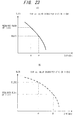
- Fig. 5 is a diagram useful in describing a linear approximation.
- SIR (dB) data at the first point is a1, b1 (dBm), and that the data at the second point is a2, b2 (dBm).
- the slope is as follows: ( a 2 - a 1 ) / 10 ( b 2 - b 1 ) / 10
- BLER ( a 2 - a 1 ) / 10 ( b 2 - b 1 ) / 10 ⁇ SIR + c
- SIR2 is calculated from the required BLER quality by the above equation
- the required BLER and the SIR of measured BLER are each found from the BLER vs. SIR characteristic when the total number of TrBks for which BLER can be measured in each service is attained, and processing for updating the target SIR is executed.
- the initial value of the target SIR is set sufficiently higher than a value (at which CRC OK is achieved) at which the required BLER can be satisfied and a CRC check is performed at the TTI (Transmission Time Interval). If a CRC error is detected, initial pull-in ends and it is considered that the steady state has been attained.
- the period of 30 ms is sufficiently short with respect to the standard time of 500 ms for pull-in. Accordingly, 30 ms is adopted as the target-SIR updating period t1 at the time of initial pull-in.
- SIR TGT SIR TGT + ⁇ SIR is input to the comparator 14 (Fig. 1) as the new target SIR.
- the period t2 or coefficient ⁇ pkt (>1) is decided in advance and stored in the ROM.
- the coefficient ⁇ pkt is decided to have a value that adheres to the stipulation of the standard time T2 in 3GPP. It is obtained by performing an experiment during normal running time in the static state, with t2 falling within 30 to 500 ms.
- the initial value of the target SIR is started from a sufficiently high value, the target-SIR updating time t1 is made 20 ms, which is the CRC check period, a CRC check is performed every 20 ms, and monitoring is performed to determine whether a CRC error has occurred. If a CRC error has not occurred, then the target SIR is decreased a prescribed amount. The moment at which a CRC error has occurred is judged to be the end of initial pull-in (this is the initial state).
- the period t2 or coefficient ⁇ amr (>1) is decided in advance and stored in the ROM.
- the coefficient ⁇ amr is decided in a range in which the stipulation of the standard time T2 in 3GPP is obeyed. It is obtained by performing an experiment during normal running time in the static state, with t2 falling within 20 to 500 ms. If a CRC error occurs, the target SIR is updated on the + side; if a CRC error does not occur, the target SIR is updated on the - side.
- Fig. 7 is a flowchart of processing for updating target SIR in the first embodiment. This is a case where the time needed to acquire the measured BLER is less than the stipulated time T1 of 3GPP Standard 1.
- the target-SIR update controller 24 determines whether communication is TrCH multiplexed communication or TrCH individual communication. If communication is TrCH individual communication, the target-SIR update controller 24 identifies the content of the service, finds the SIR conforming to the required BLER using the BLER vs. SIR characteristic that conforms to the service type, and sets this SIR in the comparator 14 as the target SIR (step 101).
- the BLER measurement unit 23 thenceforth measures BLER every updating period t1 and inputs the result to the target-SIR update controller 24 (step 103).
- the BLER measurement unit 23 thenceforth measures BLER every updating period t2 and inputs the results to the target-SIR update controller 24 (step 110).
- the target-SIR update controller 24 thenceforth checks to determine whether communication has been completed (step 115). If communication has not ended, then processing from step 110 onward is repeated.
- Fig. 8 is a second flowchart of processing for updating target SIR in the first embodiment. This is a processing flowchart for case where the time needed to acquire the measured BLER is greater than the stipulated time T1 of 3GPP Standard 1.
- the target-SIR update controller 24 determines whether communication is TrCH multiplexed communication or TrCH individual communication. If communication is TrCH individual communication, the target-SIR update controller 24 identifies the content of the service, finds the SIR conforming to the required BLER using the BLER vs. SIR characteristic that conforms to the service type, and sets this SIR in the comparator 14 as the target SIR (step 201).
- the target-SIR updating period t2 is shortened if the range of fluctuation of SIR is greater than a set value and, conversely, is made long if the range of fluctuation of SIR is small.
- Fig. 9 is a diagram illustrating the structure of a transmission power control apparatus according to a second embodiment, in which components identical with those of the first embodiment in Fig. 1 are designated by like reference characters.
- This embodiment differs in that 1 a SIR-fluctuation measurement unit 31 is provided and measures the SIR fluctuation of a receive signal in a fixed time period; 2 a measurement value of the range of SIR fluctuation has been stored in the ROM 25; and 3 the SIR updating period t1 is controlled to vary based upon the magnitudes of the measured SIR fluctuation and set value.
- the SIR-fluctuation measurement unit 31 measures the SIR fluctuation range ⁇ SIRpkt(dB) in the steady state every updating period t2 and inputs the result to the target-SIR update controller 24.
- the target-SIR update controller 24 calculates the difference between the SIR fluctuation range ⁇ SIRpkt_static(dB) in the static state and the SIR fluctuation range ⁇ SIRpkt during actual communication, and checks to see whether the difference ( ⁇ SIRpkt - ⁇ SIRpkt_static) is equal to or greater than, e.g., 3 dB. If the difference is on the order of 3 dB, then the target-SIR update controller 24 judges that the range of SIR fluctuation during actual communication is about twice that of the static state and halves the updating period t2 [makes the period (30 ⁇ ⁇ pkt)/2 (ms)] in order to make updating of the target SIR follow up the fluctuation in SIR. As a result, updating of the target SIR is hastened and it is possible for the target SIR to follow up SIR fluctuation that is due to a change in the propagation environment.
- the original updating period (30 ⁇ ⁇ pkt) is restored.
- bursts there are instances where bursts are received, and there are services having a state in which there is no data.
- BLER measurement is performed substantially during the reception of data so as not to count the total number of TrBks and number of CRC error TrBks of BLER measurement in a state in which data is not being received, the SIR conforming to this measured BLER is found, the range of SIR fluctuation is found and then the above-described control is carried out.
- control operation for updating target SIR in the first embodiment and control of updating-period fluctuation in the second embodiment are performed concurrently for the purpose of following up a change in the propagation environment momentarily.
- Fig. 10 is a flowchart of processing according to the second embodiment, in which processing steps identical with those of the processing flowchart of Fig. 7 in the first embodiment are designated by like step numbers.
- a second difference in this processing is that if the measured range of SIR fluctuation is within the set limits, a check is performed to determine whether the updating period t2 was in the shortened state up to this point (step 303), processing from step 112 onward is executed if the updating period t2 is not in the shortened state, and the updating period t2 is returned to the immediately preceding stage and processing from step 112 onward is executed if the updating period t2 is in the shortened state (step 304).
- the third embodiment is transmission power control in a case where a plurality of TrCHs of different services are multiplexed and transmitted.
- the structure of the transmission power control apparatus for realizing the third embodiment is the same as that of Fig. 1.
- the BLER measurement unit 23 (Fig. 1) inputs the measured BLER of every multiplexed TrCH (TrCH1, TrCH2) to the target-SIR update controller 24 at the SIR updating period.
- SIR TGT SIR TGT + ( ⁇ SIR + ⁇ S I R ′ ) using a value ( ⁇ SIR + ⁇ SIR') that is the result of combining the differential ⁇ SIR of TrCH1 and the ⁇ SIR' of TrCH2.
- the required BLER of the larger (inferior) of the required BLERs of TrCH1, TrCH2 is adopted as the required BLER in multiplexed communication. If this arrangement is adopted, the measured BLER of one TrCH will satisfy the required-BLER quality standard, the measured BLER will become the required-BLER standard only for this TrCH, and the other TrCH will fall outside the standard. However, it is possible to make the target SIR the lowest level, and the downlink power from the mobile station can be made the lowest while Standard 4 is satisfied.
- control for updating target SIR in the first to third embodiments is supplemented by providing a timer the time of which is longer than the target-SIR updating period t1, measuring BLER during this time and, if the value departs from standard range, performing target-SIR updating control and performing control in such a manner that the target SIR will follow up a change in the propagation environment at the time of high-speed travel of a mobile station, as when the mobile station is cruising.
- BLER measurement is performed during a certain fixed period (Tconst) longer than the target-SIR updating period t2, the target SIR is updated in a direction that will raise it by a fixed amount (Sinc_const) in a case where the measured BLER is higher than the standard value by one order of magnitude, and the target SIR is updated in a direction that will lower it by a fixed amount (Sdec_const) in a case where the measured BLER is lower than the standard value by one order of magnitude.
- BLER measurement is performed during a certain fixed period (Tconst) longer than the target-SIR updating period t2, the target SIR is updated in a direction that will raise it by a fixed amount (Sinc_const) in a case where the measured BLER is inferior to the standard range, and the target SIR is updated in a direction that will lower it by a fixed amount (Sdec_const) in a case where the measured BLER is superior to the standard range.
- Tconst Sinc_const
- Sdec_const the parameters Tconst, Sinc_const, Sdec_const can be readily changed externally.
- Total_blk ( Tconst / TTI ) ⁇ TrBk_n
- This correction processing makes it possible to cause the target SIR to follow up a fluctuation in downlink propagation environment with good precision, as by using this processing is combination with the first to third embodiments when the range of fluctuation in target SIR per unit time is very large, as when the mobile station is cruising at high speed.
- Fig. 17 is a diagram illustrating the structure of a transmission power control apparatus according to the fourth embodiment, in which components identical with those of the first embodiment in Fig. 1 are designated by like reference characters.
- This embodiment differs from the first embodiment in that it is provided with a second BLER measurement unit 41, a BLER comparator 42 and a correction unit 43.
- the second BLER measurement unit 41 performs BLER measurement over a span Tconst longer than the target-SIR updating period t2 of the first embodiment
- the BLER comparator 42 compares the measured BLER measured by the second BLER measurement unit 41 and the standard value and determines whether the difference between them is greater than a set value
- Fig. 18 is a flowchart of processing according to the second embodiment.
- Processing 401 is the processing of the second BLER measurement unit 41
- processing 402 is the processing of the BLER comparator 42
- processing 403 is the processing of the correction unit 43.
- the second BLER measurement unit 41 After outer-loop control starts (step 401a), the second BLER measurement unit 41 starts BLER measurement and continues measuring BLER until the fixed time period Tconst elapses (steps 401b, 401c). If the fixed time period Tconst elapses, the result of BLER measurement is input to the BLER comparator 42 (step 401d).
- the BLER measurement value with regard to one TrCH is made to fall within the BLER range, and BLER measurement can be placed in an excellent state above the standard with regard to other TrCHs. As a result, it is possible to exercise control such that the qualities of all TrCHs meet or exceed the standard.
- the BLER measurement value with regard to one TrCH is made to fall within the BLER range and the quality obtained is below the standard with regard to other TrCHs.
- updating of the target SIR is maintained at the lowest level, downlink power from the base station can be held to the minimum.
- fluctuation of the propagation environment is monitored.
- control for updating target SIR is performed individually and concurrently.
- the receive propagation environment fluctuates, therefore, it is possible to control the updating of target SIR more accurately.
Landscapes
- Engineering & Computer Science (AREA)
- Computer Networks & Wireless Communication (AREA)
- Signal Processing (AREA)
- Quality & Reliability (AREA)
- Mobile Radio Communication Systems (AREA)
Applications Claiming Priority (1)
| Application Number | Priority Date | Filing Date | Title |
|---|---|---|---|
| PCT/JP2003/007757 WO2004114551A1 (fr) | 2003-06-19 | 2003-06-19 | Procede et dispositif de reglage de la puissance d'emission |
Publications (3)
| Publication Number | Publication Date |
|---|---|
| EP1635483A1 true EP1635483A1 (fr) | 2006-03-15 |
| EP1635483A4 EP1635483A4 (fr) | 2010-05-05 |
| EP1635483B1 EP1635483B1 (fr) | 2012-08-01 |
Family
ID=33524150
Family Applications (1)
| Application Number | Title | Priority Date | Filing Date |
|---|---|---|---|
| EP03817196A Expired - Lifetime EP1635483B1 (fr) | 2003-06-19 | 2003-06-19 | Procede et dispositif de reglage de la puissance d'emission |
Country Status (4)
| Country | Link |
|---|---|
| US (1) | US7778656B2 (fr) |
| EP (1) | EP1635483B1 (fr) |
| JP (1) | JP4226004B2 (fr) |
| WO (1) | WO2004114551A1 (fr) |
Cited By (1)
| Publication number | Priority date | Publication date | Assignee | Title |
|---|---|---|---|---|
| EP1936830A1 (fr) * | 2006-12-18 | 2008-06-25 | NTT DoCoMo, Inc. | Terminal de communication mobile et son procédé de contrôle de la puissance de transmission |
Families Citing this family (17)
| Publication number | Priority date | Publication date | Assignee | Title |
|---|---|---|---|---|
| US7133689B2 (en) * | 2002-09-12 | 2006-11-07 | Interdigital Technology Corporation | Method and system for adjusting downlink outer loop power to control target SIR |
| JP4168857B2 (ja) * | 2003-07-31 | 2008-10-22 | トヨタ自動車株式会社 | 識別情報検査方法及び情報取得装置 |
| US7197327B2 (en) * | 2004-03-10 | 2007-03-27 | Interdigital Technology Corporation | Adjustment of target signal-to-interference in outer loop power control for wireless communication systems |
| US7907910B2 (en) * | 2004-08-02 | 2011-03-15 | Intel Corporation | Method and apparatus to vary power level of training signal |
| JP4499162B2 (ja) * | 2004-12-30 | 2010-07-07 | メッシュネットワークス インコーポレイテッド | 無線通信ネットワークにおけるノード間の通信リンクを管理するシステムおよび方法 |
| CN101444134A (zh) * | 2004-12-30 | 2009-05-27 | 网状网络公司 | 用于确定在无线通信网络中的节点的移动性的系统和方法 |
| JP2007195076A (ja) * | 2006-01-20 | 2007-08-02 | Nec Corp | 無線通信システムとその送信電力制御方法および装置 |
| JP4589250B2 (ja) * | 2006-02-21 | 2010-12-01 | 富士通株式会社 | 無線通信システムにおける電力制御装置 |
| JP4589249B2 (ja) | 2006-02-21 | 2010-12-01 | 富士通株式会社 | 無線通信システムにおける電力制御装置 |
| JP2008118514A (ja) * | 2006-11-07 | 2008-05-22 | Nec Corp | 無線通信システム、無線制御装置、無線基地局装置および電力制御方法 |
| US8265681B2 (en) * | 2007-09-12 | 2012-09-11 | Telefonaktiebolaget Lm Ericsson (Publ) | Outer loop transmit power control in wireless communication systems |
| EP2228918A1 (fr) | 2007-12-27 | 2010-09-15 | Fujitsu Limited | Procédé de contrôle de la puissance de transmission et contrôleur de puissance de transmission |
| EP2272289B1 (fr) * | 2008-04-29 | 2016-12-07 | Telefonaktiebolaget LM Ericsson (publ) | Procédé et montage pour régulation de puissance de transmission de porteuses descendantes multiples |
| EP2400804A4 (fr) * | 2009-02-23 | 2014-09-24 | Fujitsu Ltd | Dispositif de radiocommunication et procédé de régulation de puissance d'émission |
| JP5536435B2 (ja) * | 2009-12-15 | 2014-07-02 | Necパーソナルコンピュータ株式会社 | サーバ装置、通信システム、制御方法 |
| US9094919B2 (en) | 2010-11-17 | 2015-07-28 | Telefonaktiebolaget L M Ericsson (Publ) | Methods and devices for power control |
| US9480017B2 (en) * | 2013-02-11 | 2016-10-25 | Qualcomm Incorporated | Dynamic power management control |
Family Cites Families (9)
| Publication number | Priority date | Publication date | Assignee | Title |
|---|---|---|---|---|
| US5585115A (en) * | 1995-01-09 | 1996-12-17 | Edward H. Mendell Co., Inc. | Pharmaceutical excipient having improved compressability |
| DE69729784T2 (de) | 1996-06-27 | 2005-06-23 | Ntt Docomo, Inc. | Anordnung zur sendeleistungsregelung |
| DE69930239D1 (de) * | 1998-03-26 | 2006-05-04 | Samsung Electronics Co Ltd | Gerät und Verfahren zur Leistungskontrolle Orthogonaler Kanäle und Quasi-Orthogonaler Kanäle in einem CDMA Kommunikationssystem |
| JP3429674B2 (ja) * | 1998-04-28 | 2003-07-22 | 沖電気工業株式会社 | 多重通信システム |
| JP3817955B2 (ja) * | 1999-03-02 | 2006-09-06 | Kddi株式会社 | セルラーシステム送信電力制御方法 |
| DE69932102T2 (de) * | 1999-09-22 | 2007-01-11 | Fujitsu Ltd., Kawasaki | Regler für Sendeleistung |
| DE10001367A1 (de) * | 2000-01-14 | 2001-08-02 | Siemens Ag | Leistungssteuerung in Mobilfunksystemen bei unterbrochener Übertragung |
| JP3723417B2 (ja) * | 2000-06-29 | 2005-12-07 | 株式会社エヌ・ティ・ティ・ドコモ | 送信電力制御方法および移動通信システム |
| JP2002185398A (ja) | 2000-12-18 | 2002-06-28 | Sony Corp | 送信電力制御方法およびシステム |
-
2003
- 2003-06-19 EP EP03817196A patent/EP1635483B1/fr not_active Expired - Lifetime
- 2003-06-19 WO PCT/JP2003/007757 patent/WO2004114551A1/fr not_active Ceased
- 2003-06-19 JP JP2005500893A patent/JP4226004B2/ja not_active Expired - Fee Related
-
2005
- 2005-07-22 US US11/187,586 patent/US7778656B2/en not_active Expired - Fee Related
Cited By (2)
| Publication number | Priority date | Publication date | Assignee | Title |
|---|---|---|---|---|
| EP1936830A1 (fr) * | 2006-12-18 | 2008-06-25 | NTT DoCoMo, Inc. | Terminal de communication mobile et son procédé de contrôle de la puissance de transmission |
| US8000733B2 (en) | 2006-12-18 | 2011-08-16 | Ntt Docomo, Inc. | Mobile communication terminal and transmission power controlling method |
Also Published As
| Publication number | Publication date |
|---|---|
| US7778656B2 (en) | 2010-08-17 |
| JP4226004B2 (ja) | 2009-02-18 |
| EP1635483A4 (fr) | 2010-05-05 |
| WO2004114551A1 (fr) | 2004-12-29 |
| EP1635483B1 (fr) | 2012-08-01 |
| US20060003789A1 (en) | 2006-01-05 |
| JPWO2004114551A1 (ja) | 2006-07-27 |
Similar Documents
| Publication | Publication Date | Title |
|---|---|---|
| EP1635483B1 (fr) | Procede et dispositif de reglage de la puissance d'emission | |
| EP1801998B1 (fr) | Procédé de commande de puissance de transmission pour des systèmes de communication sans fil W-CDMA | |
| US7660600B2 (en) | Adjustment of target signal-to-interference in outer loop power control for wireless communication systems | |
| CN100380839C (zh) | 无线通信系统中用于调节功率控制设定点的方法和装置 | |
| US7697953B2 (en) | Outer loop transmit power control using channel-adaptive processing | |
| US7801548B2 (en) | Method and system for adjusting downlink outer loop power to control target SIR | |
| US7206291B2 (en) | Determination of parameter values of an uplink transport channel | |
| US20080132267A1 (en) | Method, access point and wtru for controlling transmission power levels of uplink/downlink communication in a wireless communication system | |
| US20070173280A1 (en) | Transmission power control apparatus and control method thereof | |
| JP2005006190A5 (fr) | ||
| US7738910B2 (en) | Transmission power control method and apparatus | |
| US7817972B2 (en) | Method and arrangement for mutual information based power control | |
| US20050152279A1 (en) | Downlink power control in wireless communications networks and methods | |
| US7082317B2 (en) | Communication apparatus and outer-loop power control method | |
| EP1494370A1 (fr) | Unite de communication et procede de regulation de la puissance de la boucle exterieure | |
| JP4785899B2 (ja) | 送信電力制御方法 | |
| JP4789705B2 (ja) | 送信電力制御方法、アウターループ制御方法及び移動局 | |
| JP2007507153A (ja) | W−cdmaモバイル通信システムにおける電力制御方法 |
Legal Events
| Date | Code | Title | Description |
|---|---|---|---|
| PUAI | Public reference made under article 153(3) epc to a published international application that has entered the european phase |
Free format text: ORIGINAL CODE: 0009012 |
|
| 17P | Request for examination filed |
Effective date: 20050816 |
|
| AK | Designated contracting states |
Kind code of ref document: A1 Designated state(s): DE FR GB IT |
|
| RBV | Designated contracting states (corrected) |
Designated state(s): DE FR GB IT |
|
| A4 | Supplementary search report drawn up and despatched |
Effective date: 20100406 |
|
| RIC1 | Information provided on ipc code assigned before grant |
Ipc: H04B 7/005 20060101ALI20100329BHEP Ipc: H04B 7/26 20060101AFI20050105BHEP Ipc: H04J 13/00 20060101ALI20100329BHEP |
|
| 17Q | First examination report despatched |
Effective date: 20110315 |
|
| GRAP | Despatch of communication of intention to grant a patent |
Free format text: ORIGINAL CODE: EPIDOSNIGR1 |
|
| RIN1 | Information on inventor provided before grant (corrected) |
Inventor name: KOBAYASHI, YUTAKAFJ MOBILE CORE TECHNOLOGIES CO., Inventor name: MURATA, SHUUICHIFJ MOBILE CORE TECHNOLOGIES CO., L |
|
| GRAS | Grant fee paid |
Free format text: ORIGINAL CODE: EPIDOSNIGR3 |
|
| GRAA | (expected) grant |
Free format text: ORIGINAL CODE: 0009210 |
|
| AK | Designated contracting states |
Kind code of ref document: B1 Designated state(s): DE FR GB IT |
|
| REG | Reference to a national code |
Ref country code: GB Ref legal event code: FG4D |
|
| RIN1 | Information on inventor provided before grant (corrected) |
Inventor name: KOBAYASHI, YUTAKA FJ MOBILE CORE TECHNOLOGIES CO., Inventor name: MURATA, SHUUICHI FJ MOBILE CORE TECHNOLOGIES CO., |
|
| REG | Reference to a national code |
Ref country code: DE Ref legal event code: R096 Ref document number: 60341704 Country of ref document: DE Effective date: 20121011 |
|
| PLBE | No opposition filed within time limit |
Free format text: ORIGINAL CODE: 0009261 |
|
| STAA | Information on the status of an ep patent application or granted ep patent |
Free format text: STATUS: NO OPPOSITION FILED WITHIN TIME LIMIT |
|
| 26N | No opposition filed |
Effective date: 20130503 |
|
| REG | Reference to a national code |
Ref country code: DE Ref legal event code: R097 Ref document number: 60341704 Country of ref document: DE Effective date: 20130503 |
|
| REG | Reference to a national code |
Ref country code: FR Ref legal event code: PLFP Year of fee payment: 13 |
|
| PGFP | Annual fee paid to national office [announced via postgrant information from national office to epo] |
Ref country code: DE Payment date: 20150616 Year of fee payment: 13 Ref country code: GB Payment date: 20150617 Year of fee payment: 13 |
|
| PGFP | Annual fee paid to national office [announced via postgrant information from national office to epo] |
Ref country code: FR Payment date: 20150608 Year of fee payment: 13 |
|
| PGFP | Annual fee paid to national office [announced via postgrant information from national office to epo] |
Ref country code: IT Payment date: 20150625 Year of fee payment: 13 |
|
| REG | Reference to a national code |
Ref country code: DE Ref legal event code: R119 Ref document number: 60341704 Country of ref document: DE |
|
| GBPC | Gb: european patent ceased through non-payment of renewal fee |
Effective date: 20160619 |
|
| REG | Reference to a national code |
Ref country code: FR Ref legal event code: ST Effective date: 20170228 |
|
| PG25 | Lapsed in a contracting state [announced via postgrant information from national office to epo] |
Ref country code: DE Free format text: LAPSE BECAUSE OF NON-PAYMENT OF DUE FEES Effective date: 20170103 Ref country code: FR Free format text: LAPSE BECAUSE OF NON-PAYMENT OF DUE FEES Effective date: 20160630 |
|
| PG25 | Lapsed in a contracting state [announced via postgrant information from national office to epo] |
Ref country code: GB Free format text: LAPSE BECAUSE OF NON-PAYMENT OF DUE FEES Effective date: 20160619 |
|
| PG25 | Lapsed in a contracting state [announced via postgrant information from national office to epo] |
Ref country code: IT Free format text: LAPSE BECAUSE OF NON-PAYMENT OF DUE FEES Effective date: 20160619 |